How to assemble IKEA BILLY bookcase

BILLY bookcase, white, 311/2x11x791/2"

This guide covers the white IKEA BILLY bookcase, article 205.220.46, measuring 31 1/2 inches wide and 79 1/2 inches high. Follow the bookcase diagrams and video for this model.

View on IKEA
BILLY bookcase

Interactive assembly guide

Step-by-Step Instructions

1 different parts, 1 boxes total — click on a package to see step-by-step assembly instructions

BILLY Bookcase

205.220.46

x1

11 ¾ "

Width

5 "

Height

81 ¼ "

Length

87 lb 10 oz

Weight

Start Assembly

Written guide

Step-by-step instructions with diagrams

Follow the numbered assembly steps below, or open the interactive guide above to track progress and zoom into each diagram. This guide includes 12 illustrated steps.

BILLY Bookcase

  1. Before you begin

    Multilingual tip-over safety warning page stating that serious or fatal crushing injuries can occur if furniture tips over and that the furniture must be attached to the wall with suitable wall fasteners.
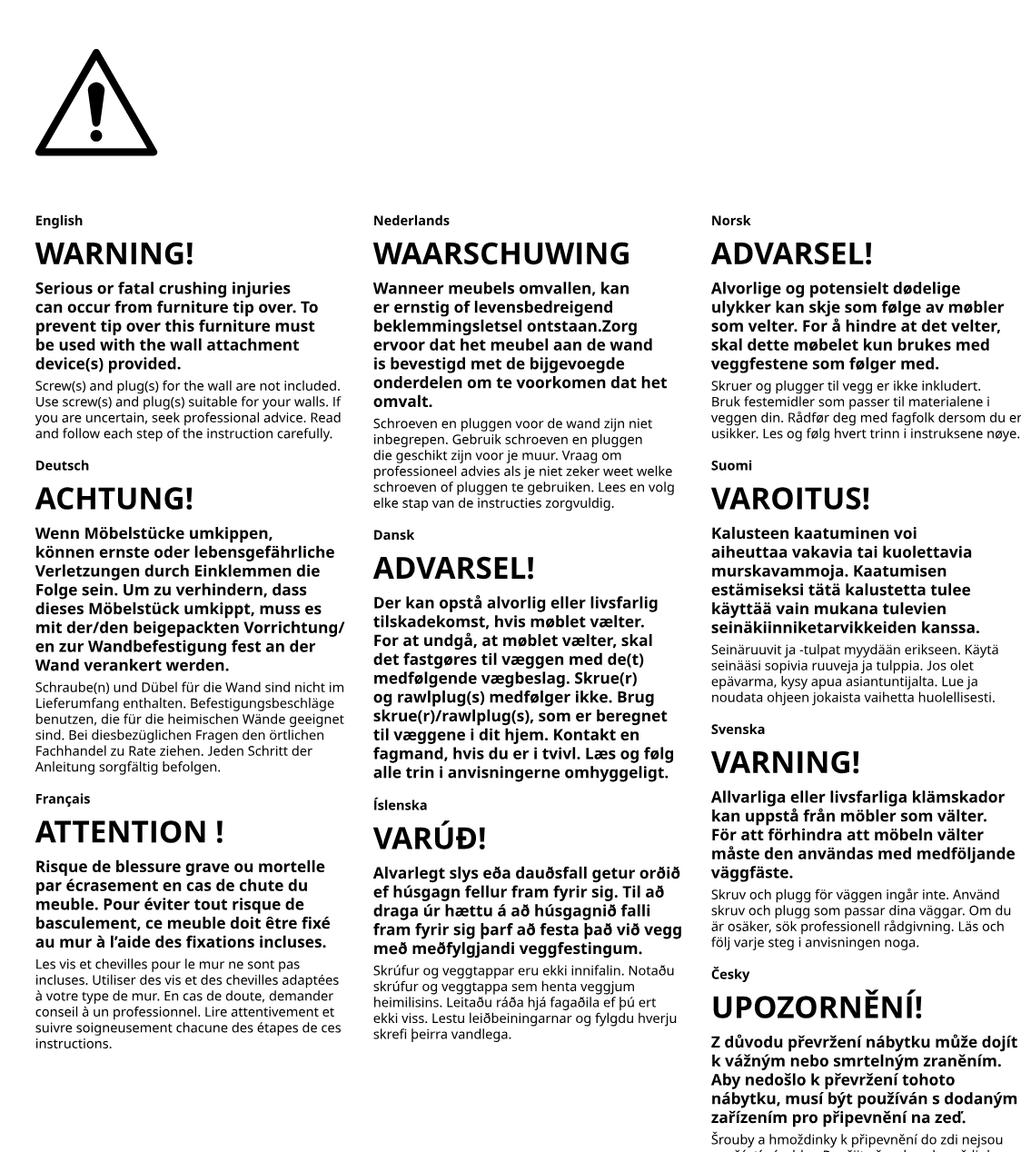
    Illustration for assembly note: Multilingual tip-over safety warning page stating that serious or fatal crushing injuries can occur if furniture tips over and that the furniture must be attached to the wall with suitable wall fasteners.
  2. Before you begin

    Preparation and safety guidance panels show required tools, advise that assembly should not be done alone and may require two people, instruct assembling on a soft surface instead of directly on the floor to avoid damage, and suggest consulting the manual or contacting IKEA for help if needed.
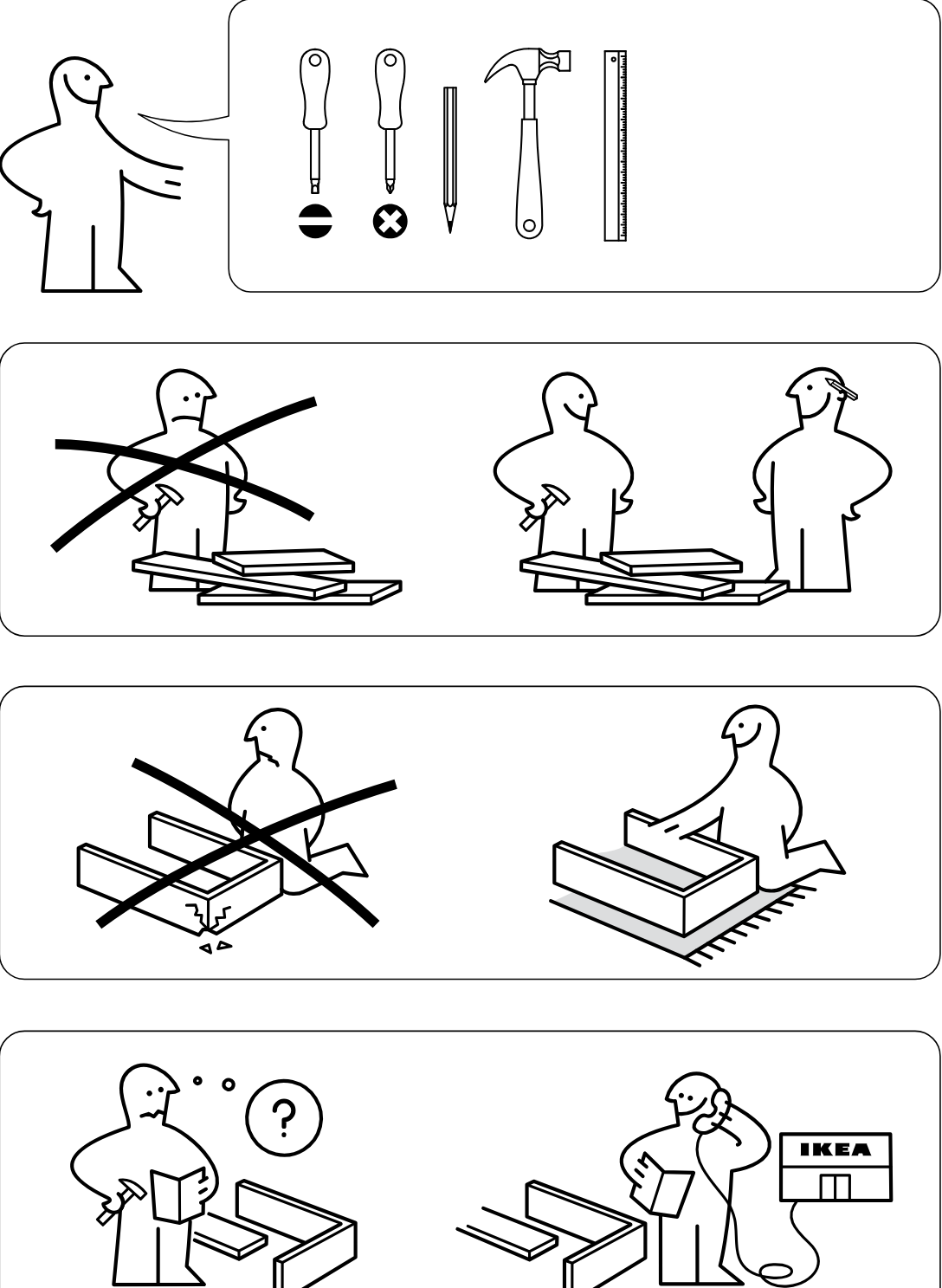
    Illustration for assembly note: Preparation and safety guidance panels show required tools, advise that assembly should not be done alone and may require two people, instruct assembling on a soft surface instead of directly on the floor to avoid damage, and suggest consulting the manual or contacting IKEA for help if needed.
  3. Before you begin

    Top safety panel shows the tall shelving unit must be secured upright and not climbed on or used unstabilized.
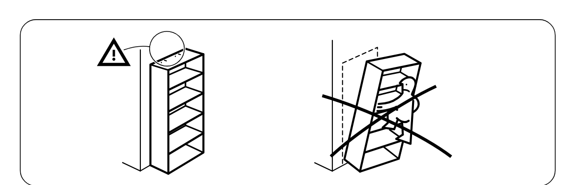
    Illustration for assembly note: Top safety panel shows the tall shelving unit must be secured upright and not climbed on or used unstabilized.
  4. Step 1

    Insert 16 wooden dowels into the predrilled edge holes of the shelf panels and the narrow rail as shown, with a zoom detail of the dowel placement.
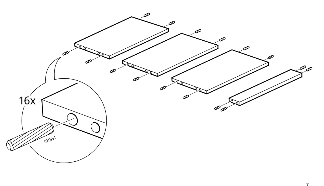
    Diagram for step 1: Insert 16 wooden dowels into the predrilled edge holes of the shelf panels and the narrow rail as shown, with a zoom detail of the dowel placement.
  5. Step 2

    Twelve screw studs are tightened into the predrilled holes of the long panels with a screwdriver.
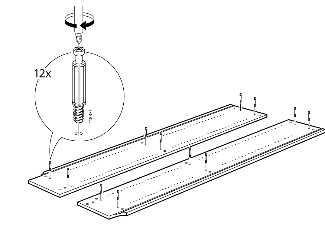
    Diagram for step 2: Twelve screw studs are tightened into the predrilled holes of the long panels with a screwdriver.
  6. Step 3

    Two upright side panels are aligned and lowered onto the connector pins of the long base panel, with inset comparisons showing the correct orientation of the dowels.
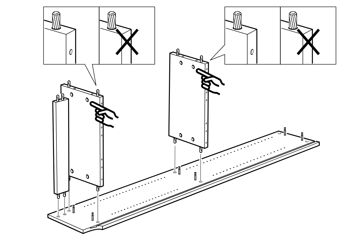
    Diagram for step 3: Two upright side panels are aligned and lowered onto the connector pins of the long base panel, with inset comparisons showing the correct orientation of the dowels.
  7. Step 4

    Two vertical panels are positioned onto the long base panel and four cam locks are inserted and turned to secure the panels, as shown in the zoom callouts.
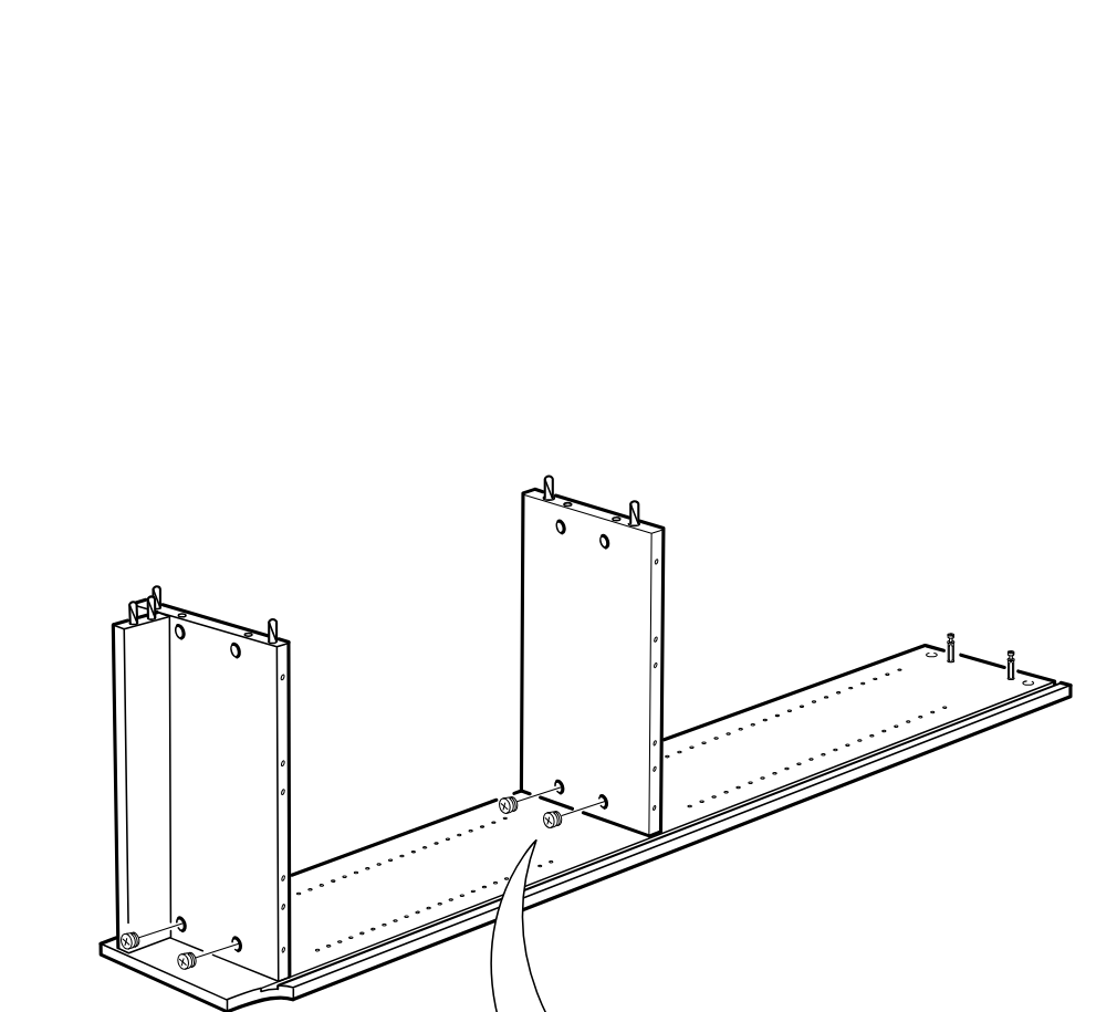
    Diagram for step 4: Two vertical panels are positioned onto the long base panel and four cam locks are inserted and turned to secure the panels, as shown in the zoom callouts.
  8. Step 5

    Two side panels are positioned onto the base panel and the cam locks are inserted and turned to secure them, with one orientation reminder panel and two zoom callouts showing the cam hardware and tightening direction.
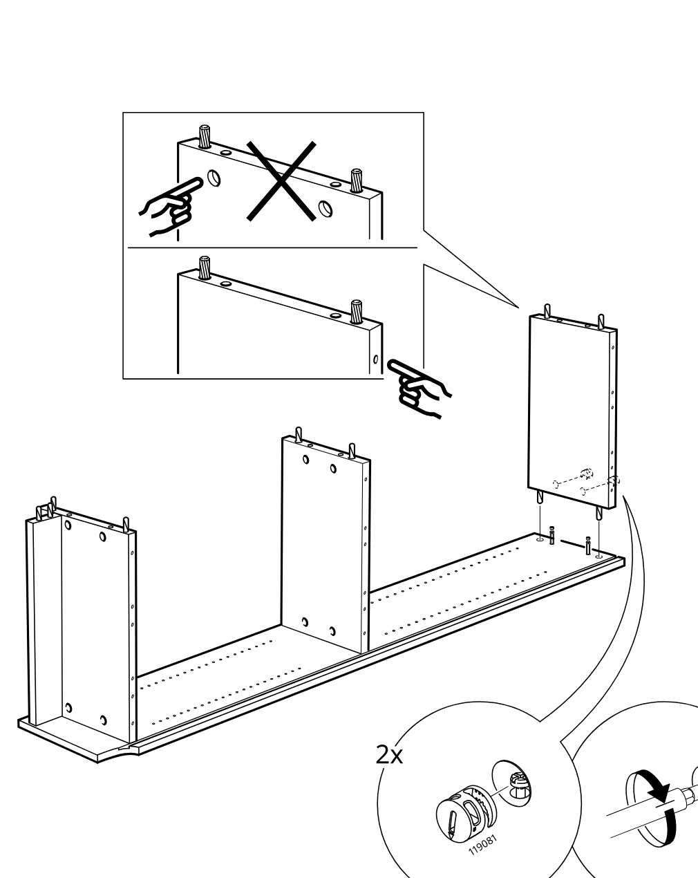
    Diagram for step 5: Two side panels are positioned onto the base panel and the cam locks are inserted and turned to secure them, with one orientation reminder panel and two zoom callouts showing the cam hardware and tightening direction.
  9. Step 6

    The top panel is lowered onto the three upright dividers and side panels to form the cabinet frame.
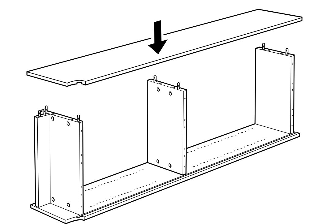
    Diagram for step 6: The top panel is lowered onto the three upright dividers and side panels to form the cabinet frame.
  10. Step 7

    Six cam locks are inserted into the top panel and turned to secure the top to the side and center panels.
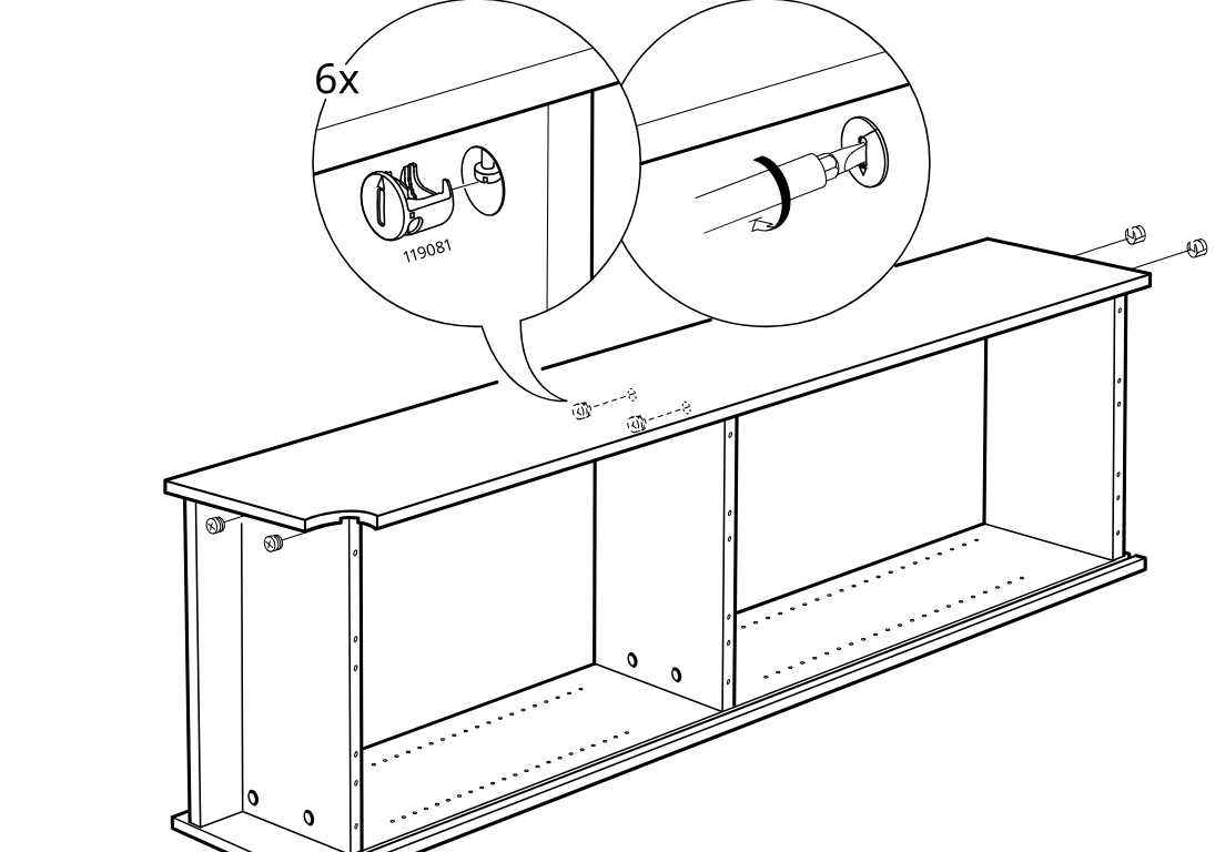
    Diagram for step 7: Six cam locks are inserted into the top panel and turned to secure the top to the side and center panels.
  11. Step 8

    Slide the long bottom panel into the grooves of the side assembly while keeping the folded edge oriented correctly, as shown in the inset.
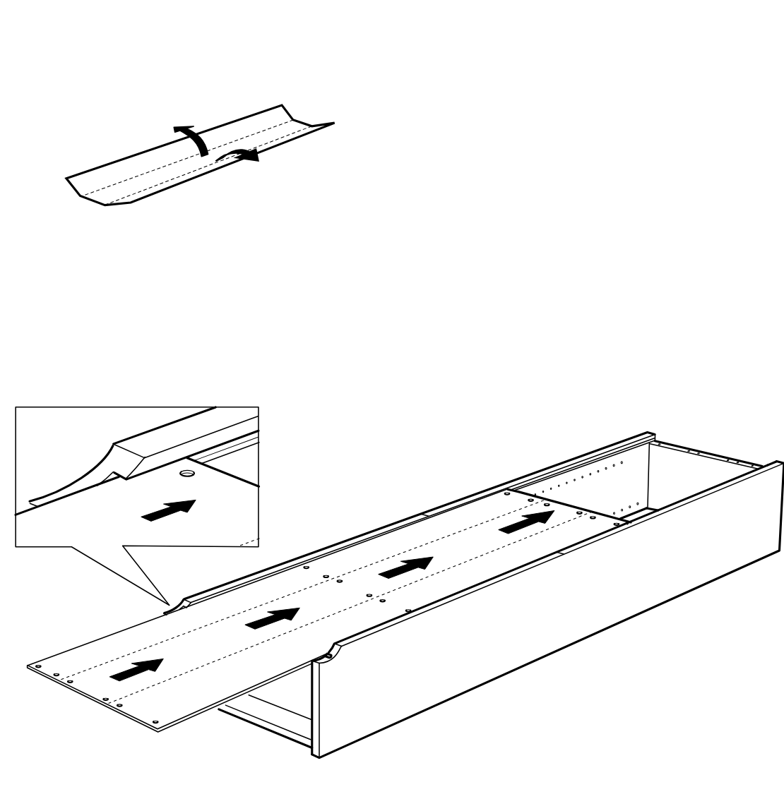
    Diagram for step 8: Slide the long bottom panel into the grooves of the side assembly while keeping the folded edge oriented correctly, as shown in the inset.
  12. Step 9

    Install 18 cover plugs into the predrilled holes along the long panel, using either ribbed plug 151706 or cap plug 151705 as shown in the zoom callouts.
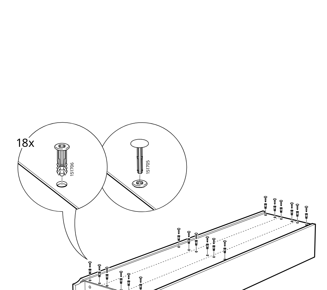
    Diagram for step 9: Install 18 cover plugs into the predrilled holes along the long panel, using either ribbed plug 151706 or cap plug 151705 as shown in the zoom callouts.
  13. Before you begin

    Safety panel shows the tall cabinet must be secured to the wall and must not be climbed on or left unsecured.
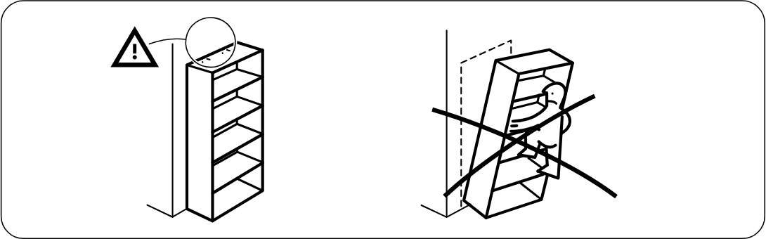
    Illustration for assembly note: Safety panel shows the tall cabinet must be secured to the wall and must not be climbed on or left unsecured.
  14. Step 10

    Attach two wall brackets to the top of the cabinet and fasten them to the wall, using either the long screw with washer or the shorter screw with washer through the slotted bracket.
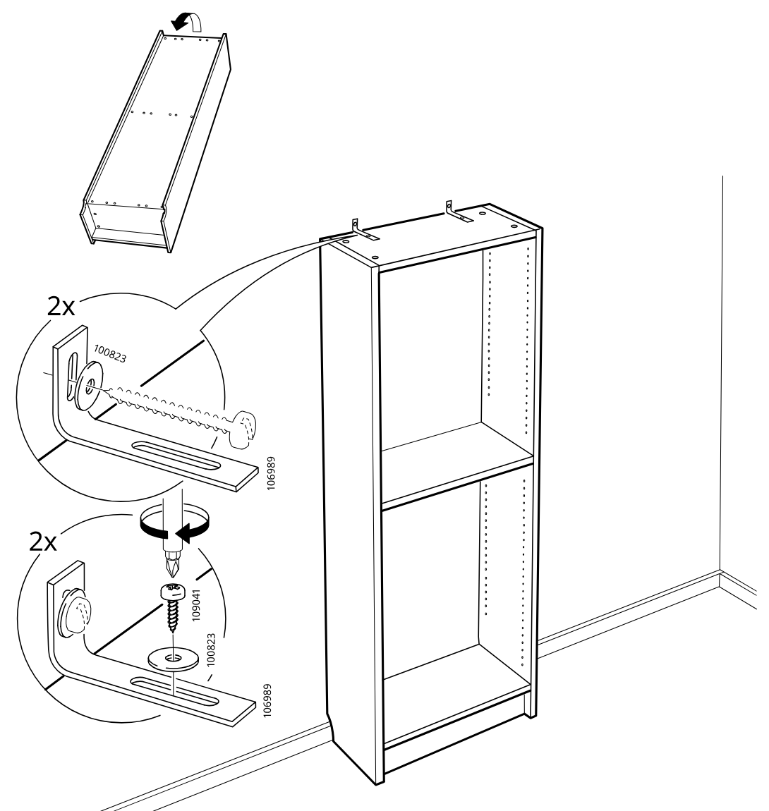
    Diagram for step 10: Attach two wall brackets to the top of the cabinet and fasten them to the wall, using either the long screw with washer or the shorter screw with washer through the slotted bracket.
  15. Step 11

    Insert sixteen shelf support pins into the cabinet side panels at the desired hole positions, as shown in the zoom callout.
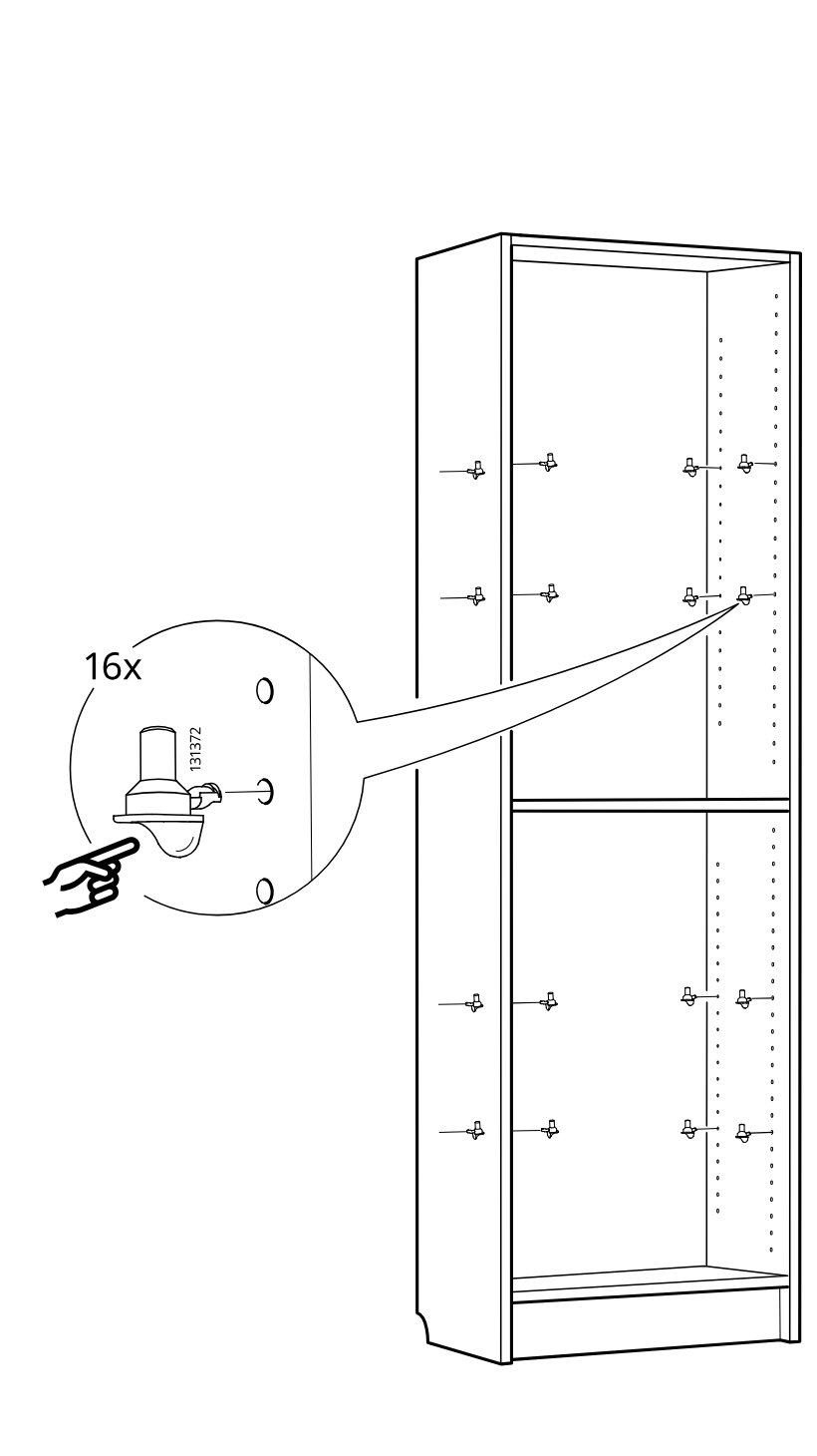
    Diagram for step 11: Insert sixteen shelf support pins into the cabinet side panels at the desired hole positions, as shown in the zoom callout.
  16. Step 12

    Insert four shelves into the cabinet and seat each shelf onto the support pins, as shown in the zoomed detail.
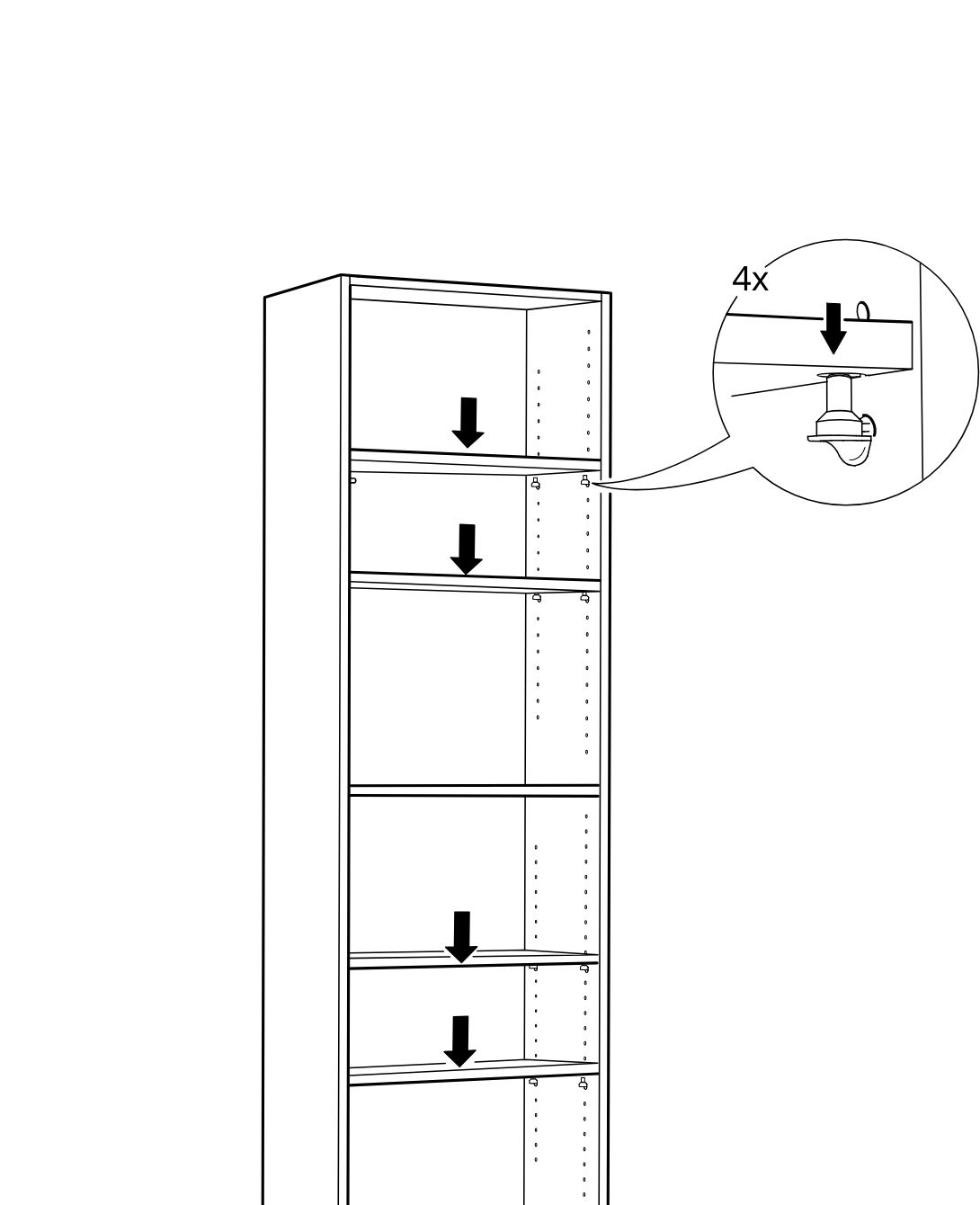
    Diagram for step 12: Insert four shelves into the cabinet and seat each shelf onto the support pins, as shown in the zoomed detail.

Video guide