How to assemble IKEA BRIMNES 3-drawer dresser

BRIMNES 3-drawer dresser, white, 303/4x181/8x373/8"

This guide covers the white IKEA BRIMNES 3-drawer dresser, article 405.728.32. Use the dresser assembly diagrams and video for this model, checking the article number before starting.

View on IKEA
BRIMNES 3-drawer dresser

Interactive assembly guide

Step-by-Step Instructions

1 different parts, 1 boxes total — click on a package to see step-by-step assembly instructions

BRIMNES 3-drawer dresser

405.728.32

x1

19 "

Width

4 "

Height

38 ¼ "

Length

59 lb 5 oz

Weight

Start Assembly

Written guide

Step-by-step instructions with diagrams

Follow the numbered assembly steps below, or open the interactive guide above to track progress and zoom into each diagram. This guide includes 35 illustrated steps.

BRIMNES 3-drawer dresser

  1. Before you begin

    Top-of-manual anti-tipover safety warnings with prohibition/requirement pictograms and multilingual text (English, French, Spanish) instructing wall anchoring, no TV placement, child safety, one drawer at a time, and heavy items in lower drawers.
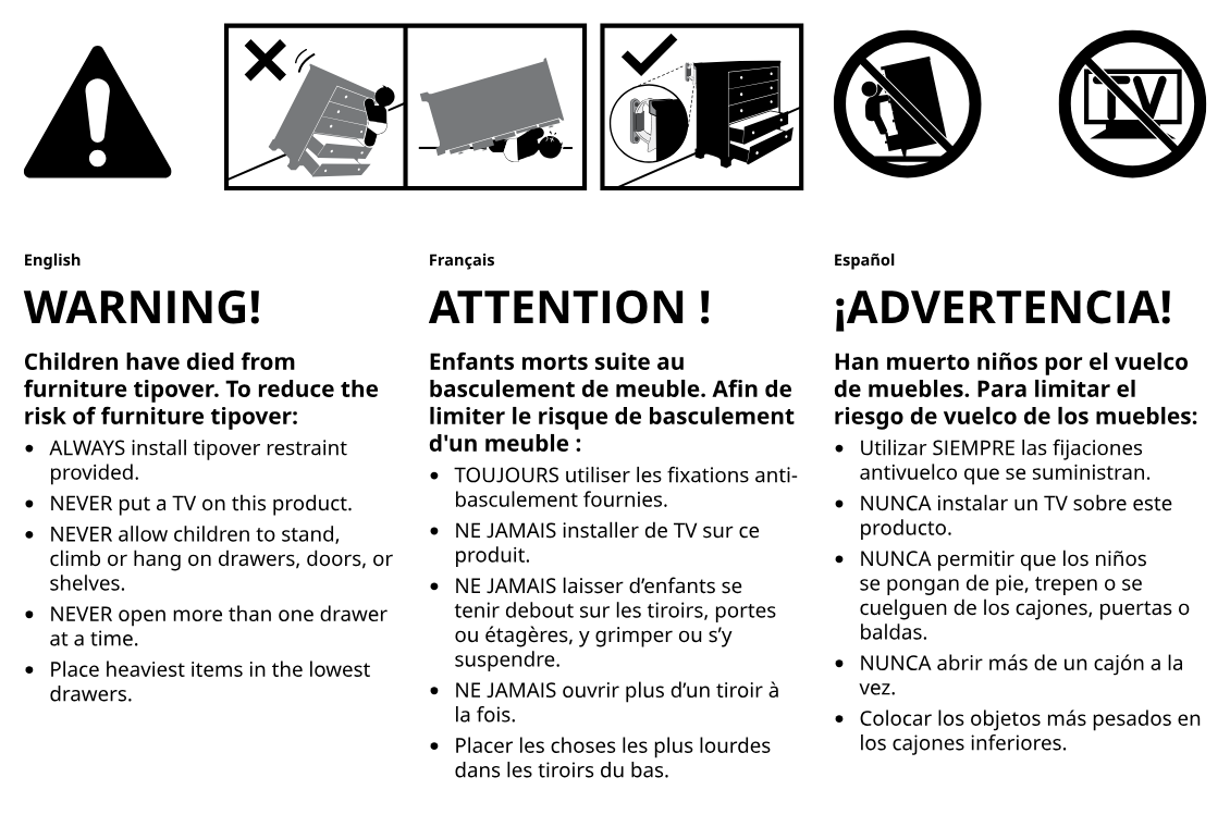
    Illustration for assembly note: Top-of-manual anti-tipover safety warnings with prohibition/requirement pictograms and multilingual text (English, French, Spanish) instructing wall anchoring, no TV placement, child safety, one drawer at a time, and heavy items in lower drawers.
  2. Before you begin

    Tool and wall-type preparation guidance shows required screwdrivers, pencil, hammer, drill, drill bit sizes, and which anchor/bit combinations to use for masonry, hollow, and wood walls.
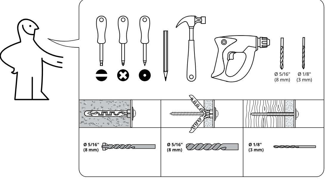
    Illustration for assembly note: Tool and wall-type preparation guidance shows required screwdrivers, pencil, hammer, drill, drill bit sizes, and which anchor/bit combinations to use for masonry, hollow, and wood walls.
  3. Before you begin

    Hardware bag and tip-over prevention warning shows wall-fixing hardware and indicates loading the unit requires securing it to the wall.
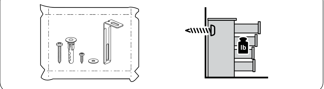
    Illustration for assembly note: Hardware bag and tip-over prevention warning shows wall-fixing hardware and indicates loading the unit requires securing it to the wall.
  4. Before you begin

    Two-person handling safety panel shows proper teamwork and forbids assembling alone.
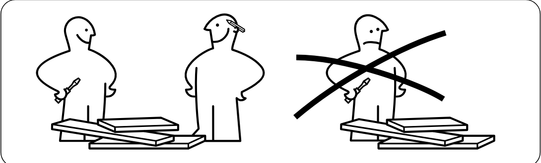
    Illustration for assembly note: Two-person handling safety panel shows proper teamwork and forbids assembling alone.
  5. Before you begin

    Illustration for assembly note:
  6. Before you begin

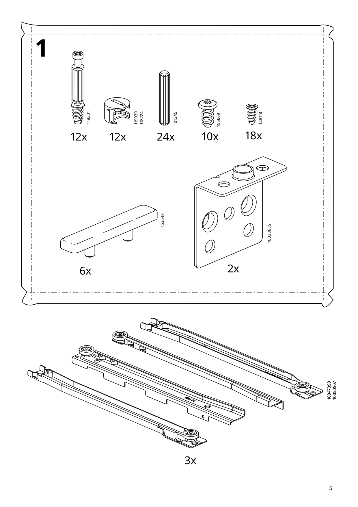
    Parts-bag panel for step 2 showing required hardware: 101345 (12x), 110519 (12x), 118331 (12x), 119030/118224 cam lock (12x), 109567 (6x), 105344 (6x), 146114 (12x), and 107091 pads (3x).
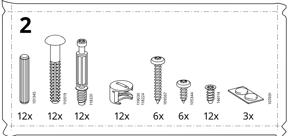
    Illustration for assembly note: Parts-bag panel for step 2 showing required hardware: 101345 (12x), 110519 (12x), 118331 (12x), 119030/118224 cam lock (12x), 109567 (6x), 105344 (6x), 146114 (12x), and 107091 pads (3x).
  7. Step 1

    Place panels IKEA CR and IKEA CL on a soft surface and tighten 9 screws (146114) into the predrilled positions shown in the two zoom callouts.
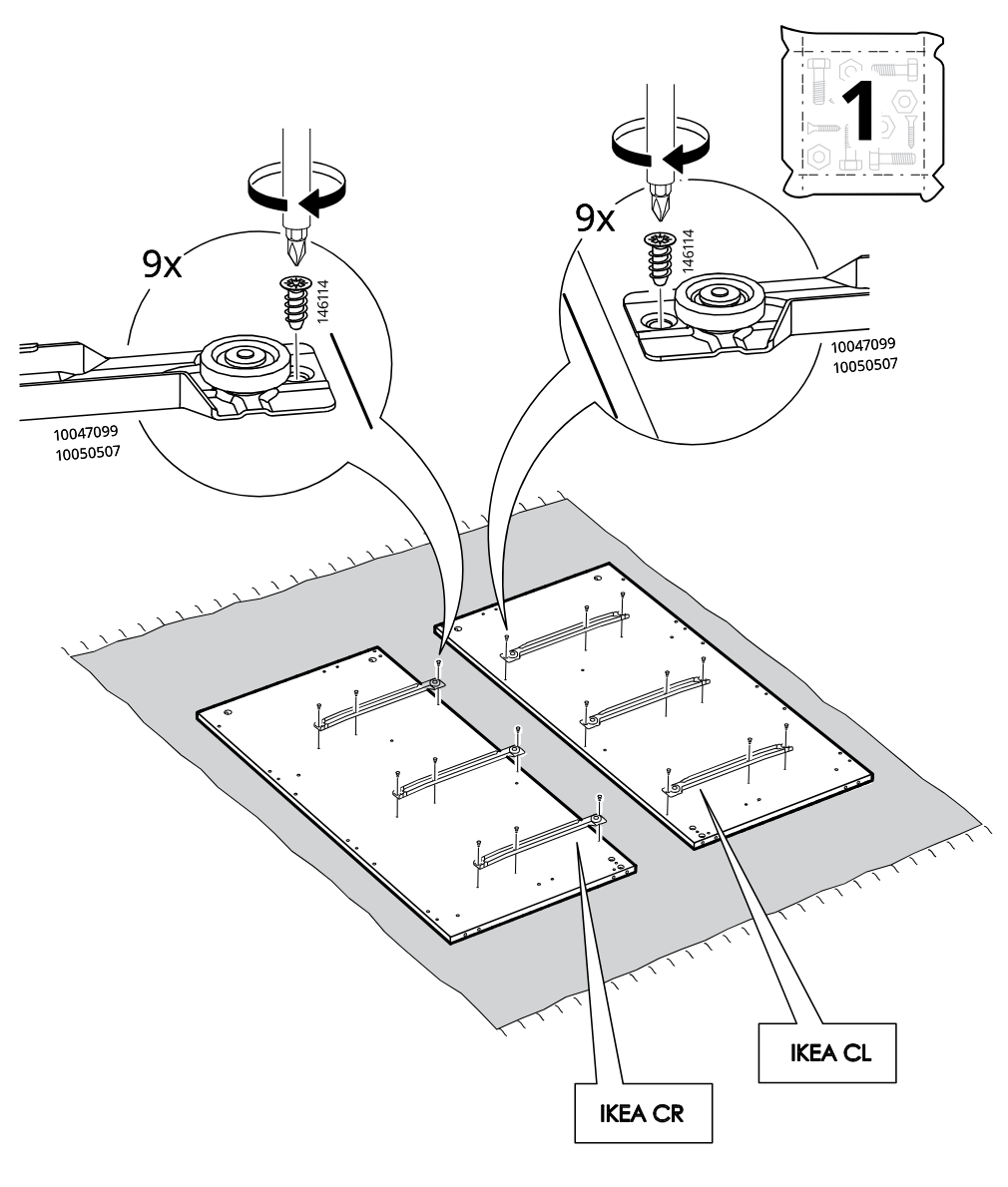
    Diagram for step 1: Place panels IKEA CR and IKEA CL on a soft surface and tighten 9 screws (146114) into the predrilled positions shown in the two zoom callouts.
  8. Step 2

    The installer screws eight cam bolts (118331) into the predrilled holes of two large side panels, with the zoom callout showing the screw orientation and turning direction.
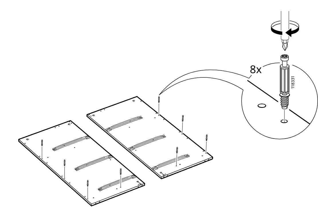
    Diagram for step 2: The installer screws eight cam bolts (118331) into the predrilled holes of two large side panels, with the zoom callout showing the screw orientation and turning direction.
  9. Step 3

    The installer inserts twenty wooden dowels (101345) into the edge holes across four shelf panels and one rail piece, as indicated by the enlarged hole-and-dowel callout.
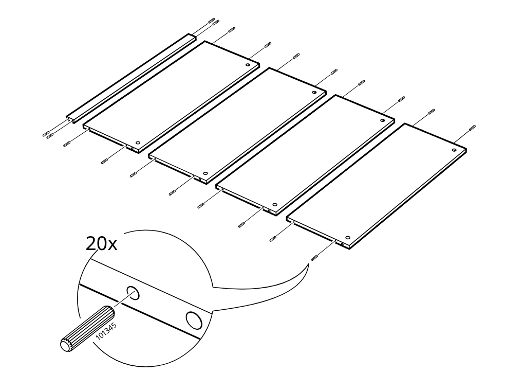
    Diagram for step 3: The installer inserts twenty wooden dowels (101345) into the edge holes across four shelf panels and one rail piece, as indicated by the enlarged hole-and-dowel callout.
  10. Step 4

    A long narrow upright panel is lowered onto the left side of the base assembly next to the two horizontal boards.
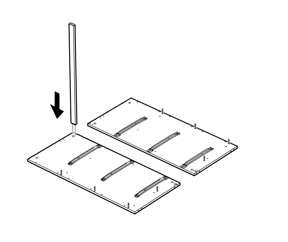
    Diagram for step 4: A long narrow upright panel is lowered onto the left side of the base assembly next to the two horizontal boards.
  11. Step 5

    A larger vertical side panel is lowered into position on the front-right area of the base while the previously installed upright remains at the back-left.
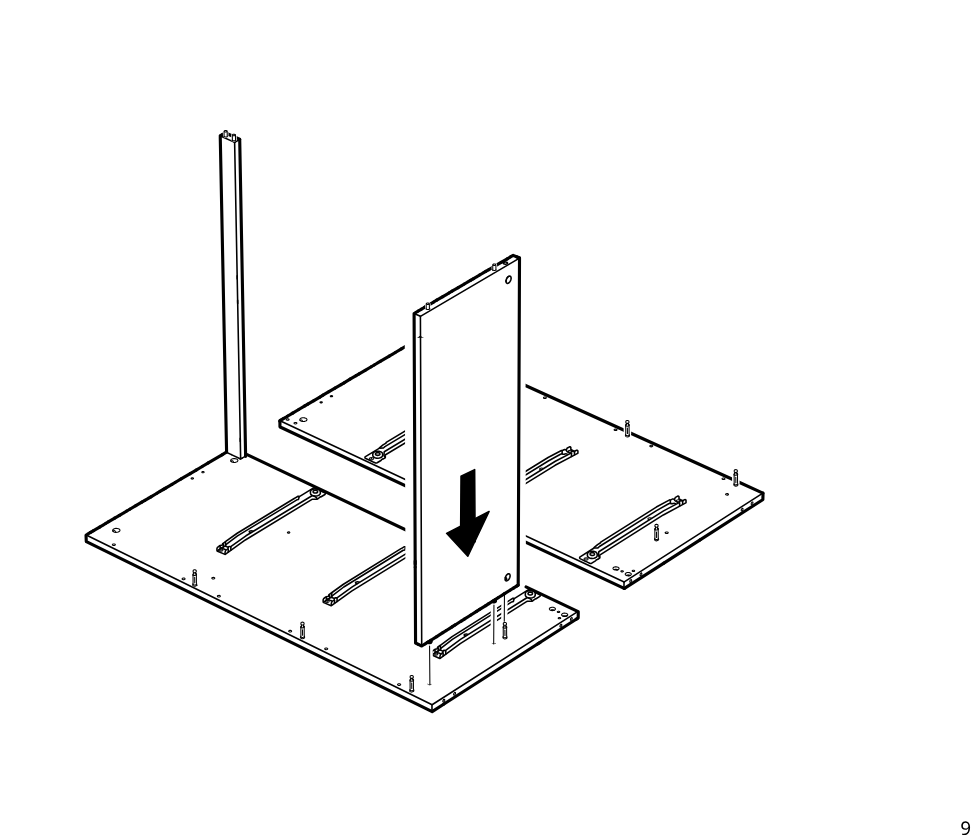
    Diagram for step 5: A larger vertical side panel is lowered into position on the front-right area of the base while the previously installed upright remains at the back-left.
  12. Step 6

    Three vertical panels are lowered onto the base between the side structures, aligning into position as indicated by downward arrows.
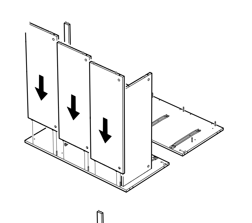
    Diagram for step 6: Three vertical panels are lowered onto the base between the side structures, aligning into position as indicated by downward arrows.
  13. Step 7

    Four cam locks are inserted and tightened from the lower side area to secure the installed panels, with a zoom callout showing lock orientation and screwdriver rotation.
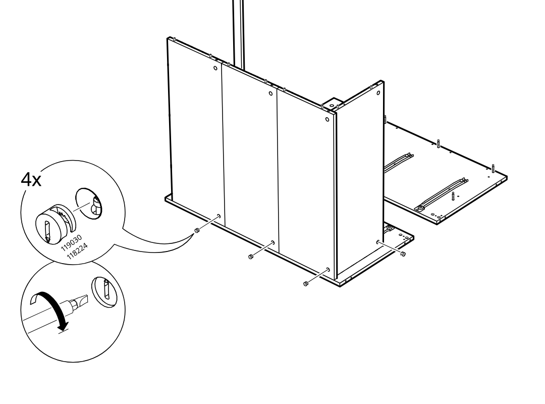
    Diagram for step 7: Four cam locks are inserted and tightened from the lower side area to secure the installed panels, with a zoom callout showing lock orientation and screwdriver rotation.
  14. Step 8

    The two metal corner brackets are fastened onto both ends of the long rail with two screws at each end, with a zoom callout showing tightening direction and screw details.
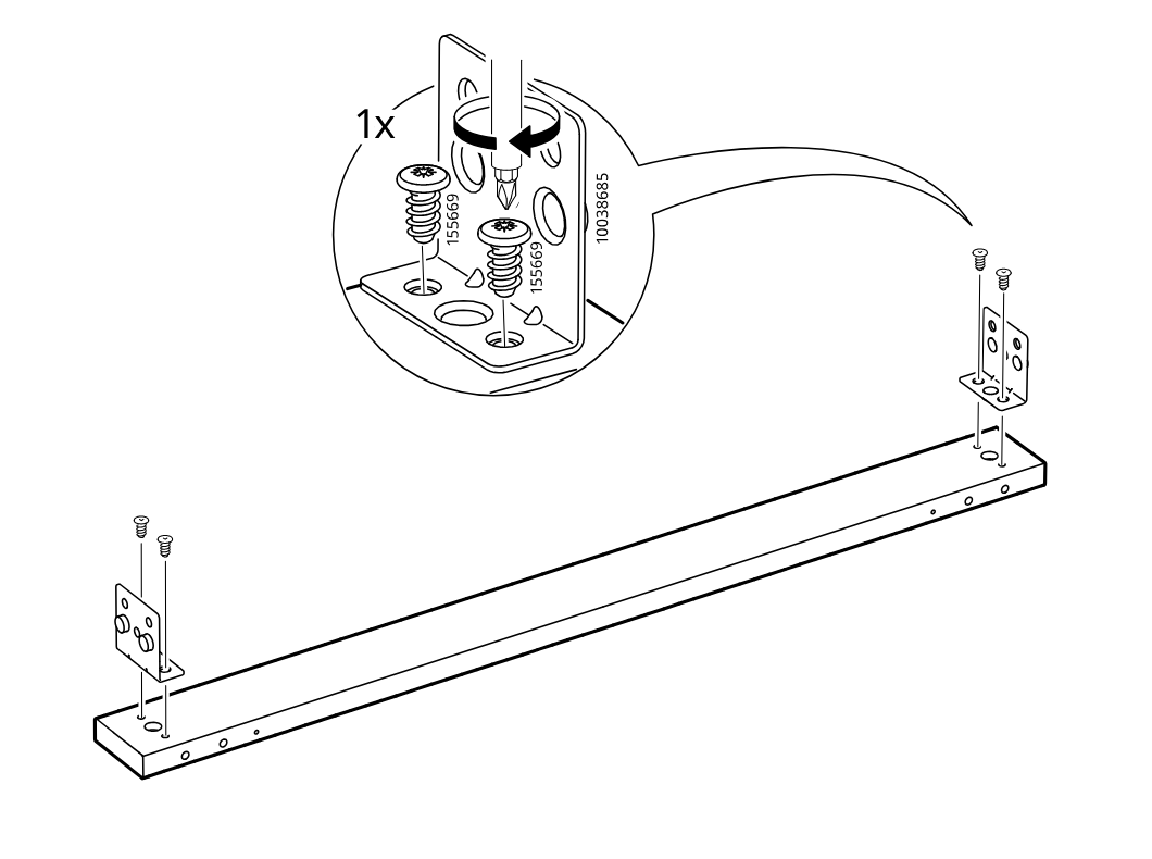
    Diagram for step 8: The two metal corner brackets are fastened onto both ends of the long rail with two screws at each end, with a zoom callout showing tightening direction and screw details.
  15. Step 9

    Two plastic end caps are pushed into the side holes near each end of the rail, as shown by arrows and a zoom callout identifying part 153548.
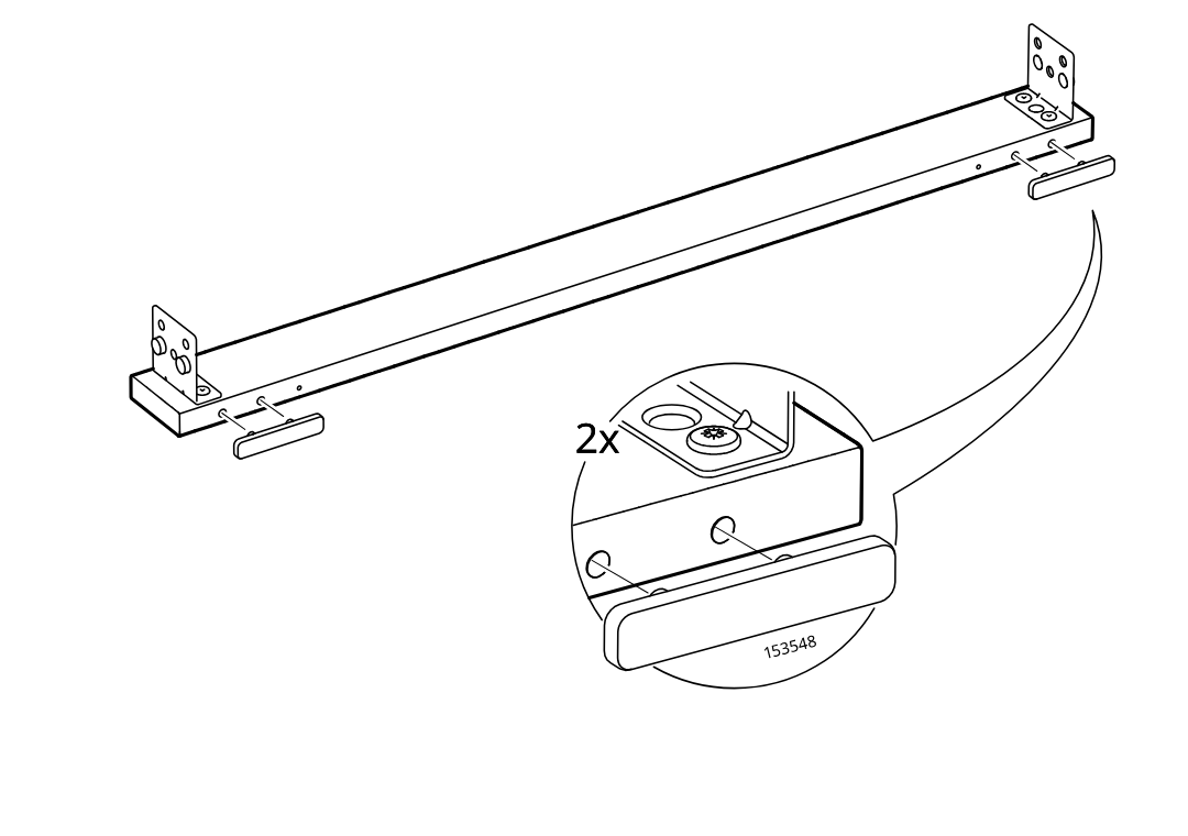
    Diagram for step 9: Two plastic end caps are pushed into the side holes near each end of the rail, as shown by arrows and a zoom callout identifying part 153548.
  16. Step 10

    The side frame is lowered onto the base and one screw is tightened into the corner bracket as shown in the zoomed callout.
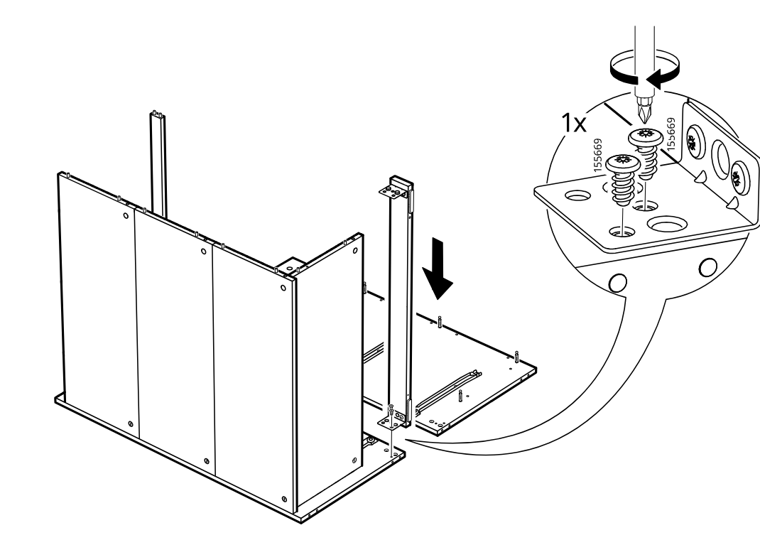
    Diagram for step 10: The side frame is lowered onto the base and one screw is tightened into the corner bracket as shown in the zoomed callout.
  17. Step 11

    The top panel is rotated into position and lowered down onto the cabinet frame.
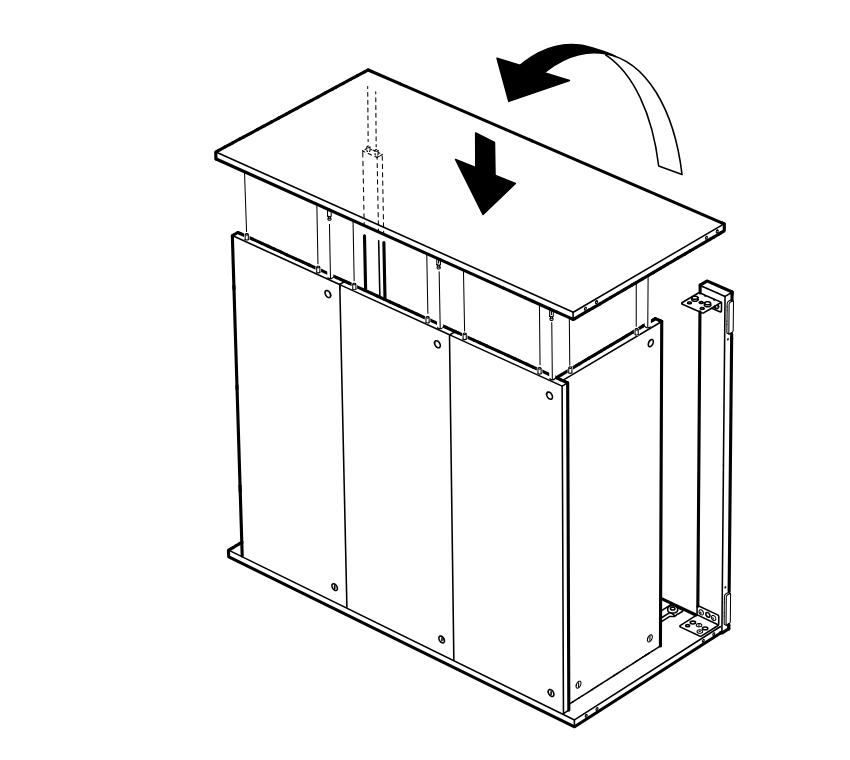
    Diagram for step 11: The top panel is rotated into position and lowered down onto the cabinet frame.
  18. Step 12

    Insert four cam locks into the side panel holes and turn them upward to lock.
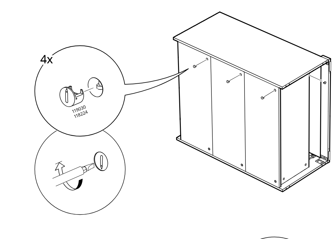
    Diagram for step 12: Insert four cam locks into the side panel holes and turn them upward to lock.
  19. Step 13

    Secure the corner bracket with one screw using a screwdriver, as shown in the zoom callout.
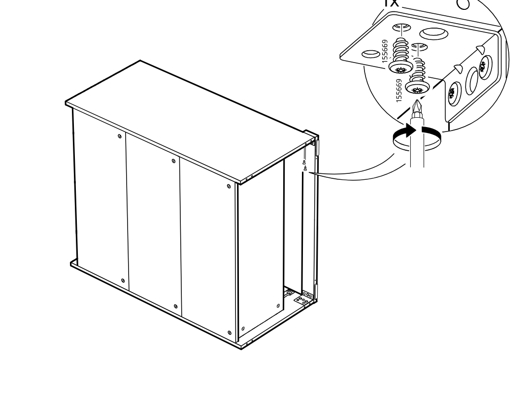
    Diagram for step 13: Secure the corner bracket with one screw using a screwdriver, as shown in the zoom callout.
  20. Step 14

    Insert four cover caps (part 153548) onto the exposed side holes near the cabinet’s right frame, as indicated by the zoom callout.
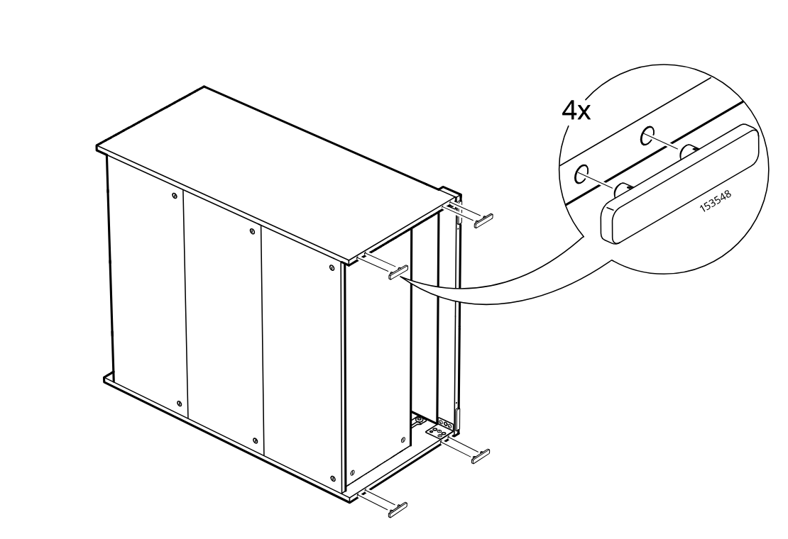
    Diagram for step 14: Insert four cover caps (part 153548) onto the exposed side holes near the cabinet’s right frame, as indicated by the zoom callout.
  21. Step 15

    The installer positions two metal brackets on the panel and fastens each with a screw and washer as shown in the zoom detail.
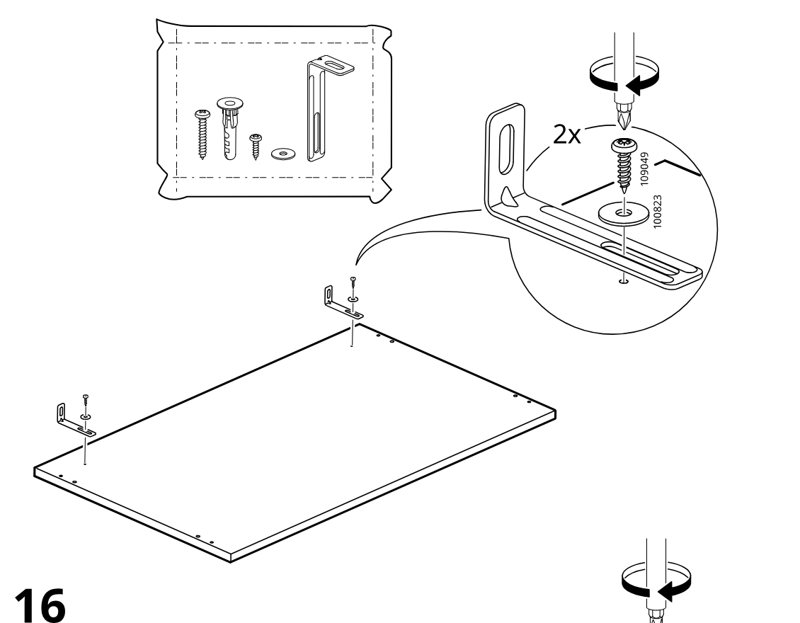
    Diagram for step 15: The installer positions two metal brackets on the panel and fastens each with a screw and washer as shown in the zoom detail.
  22. Step 16

    The installer screws four threaded inserts into the panel holes while keeping the previously mounted brackets in place.
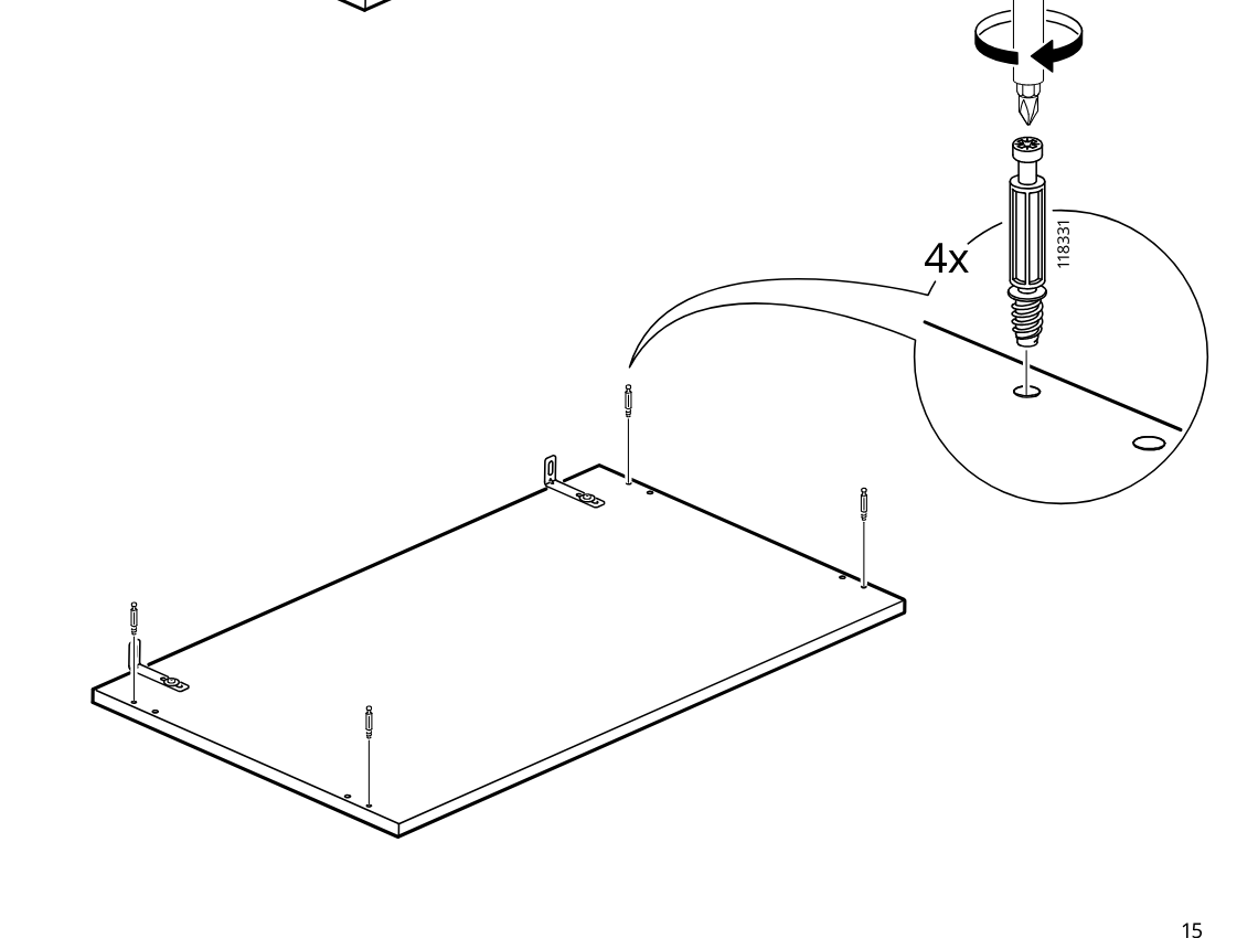
    Diagram for step 16: The installer screws four threaded inserts into the panel holes while keeping the previously mounted brackets in place.
  23. Step 17

    The cabinet frame is turned and four dowels (101345) are inserted into the top edge holes, with a zoom callout showing the dowel placement and quantity.
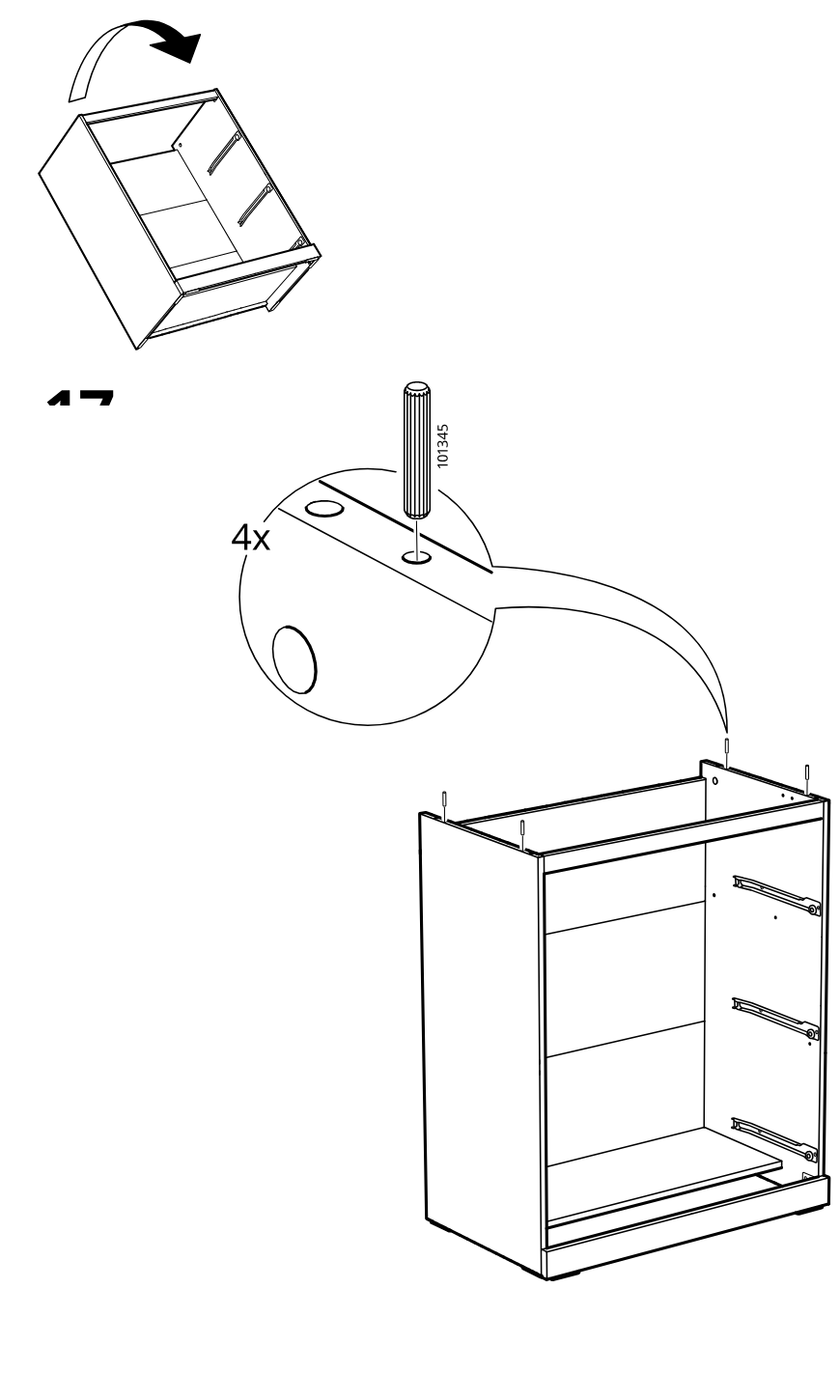
    Diagram for step 17: The cabinet frame is turned and four dowels (101345) are inserted into the top edge holes, with a zoom callout showing the dowel placement and quantity.
  24. Step 18

    The top panel is lowered onto the cabinet frame and aligned with the upper fittings, with a zoom inset showing the connector and bracket detail.
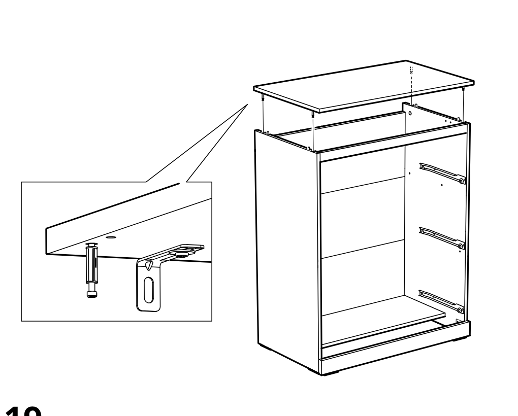
    Diagram for step 18: The top panel is lowered onto the cabinet frame and aligned with the upper fittings, with a zoom inset showing the connector and bracket detail.
  25. Step 19

    Four cam locks are inserted and turned with a screwdriver to secure the top panel to the cabinet.
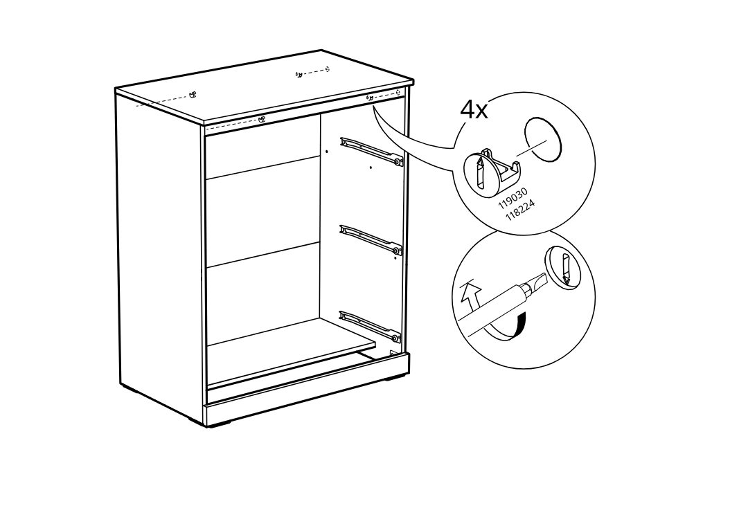
    Diagram for step 19: Four cam locks are inserted and turned with a screwdriver to secure the top panel to the cabinet.
  26. Step 20

    The wall bracket is aligned and fixed at the top rear of the cabinet using the shown fasteners, then tightened with a screwdriver and finished with a final tightening tool.
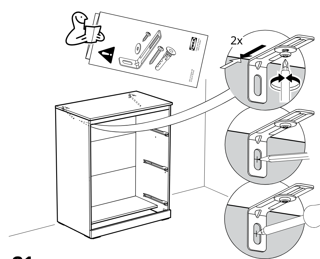
    Diagram for step 20: The wall bracket is aligned and fixed at the top rear of the cabinet using the shown fasteners, then tightened with a screwdriver and finished with a final tightening tool.
  27. Step 21

    The cabinet is pushed sideways into its final position as indicated by the horizontal arrow.
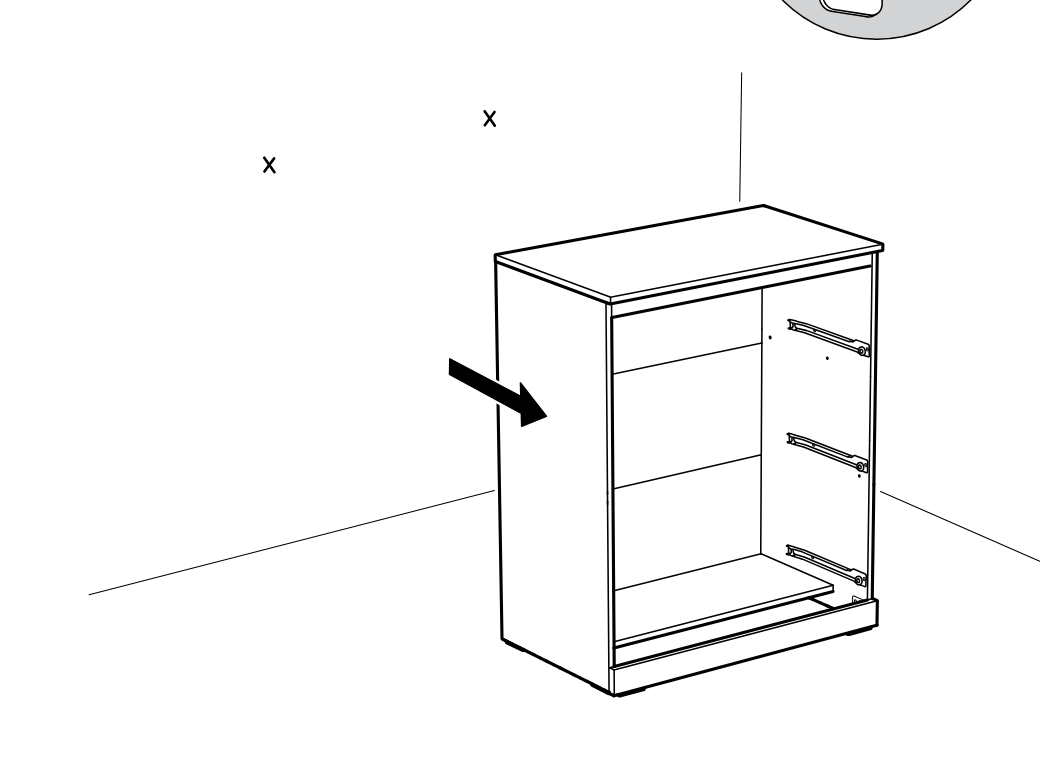
    Diagram for step 21: The cabinet is pushed sideways into its final position as indicated by the horizontal arrow.
  28. Before you begin

    Wall anchoring guidance panel with QR code, secure-it URL, and a tip-over prevention illustration showing fastening furniture to a wall.
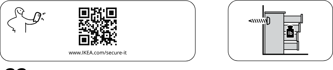
    Illustration for assembly note: Wall anchoring guidance panel with QR code, secure-it URL, and a tip-over prevention illustration showing fastening furniture to a wall.
  29. Before you begin

    Reference panel A for solid wall anchoring, showing plug and screw usage, required 5/16 in (8 mm) drill bit, marking, drilling depth 2 3/4 in (70 mm), and hammering in wall plug.
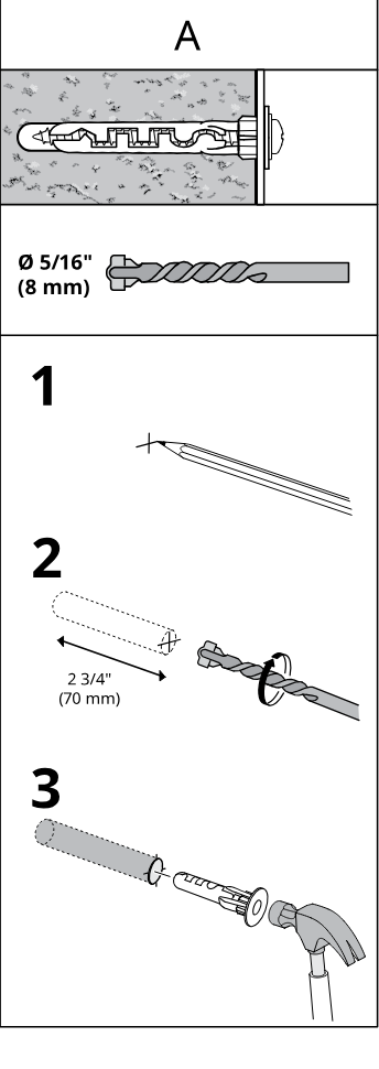
    Illustration for assembly note: Reference panel A for solid wall anchoring, showing plug and screw usage, required 5/16 in (8 mm) drill bit, marking, drilling depth 2 3/4 in (70 mm), and hammering in wall plug.
  30. Before you begin

    Reference panel B for hollow wall anchoring, showing screw and plug usage, required 5/16 in (8 mm) drill bit, marking, drilling depth approximately 1 1/4 in (30 mm), and inserting wall plug.
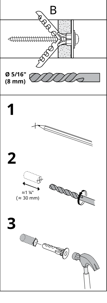
    Illustration for assembly note: Reference panel B for hollow wall anchoring, showing screw and plug usage, required 5/16 in (8 mm) drill bit, marking, drilling depth approximately 1 1/4 in (30 mm), and inserting wall plug.
  31. Before you begin

    Reference panel C for solid wood anchoring, showing screw without plug, required 1/8 in (3 mm) drill bit, marking, and drilling depth approximately 1 1/4 in (30 mm).
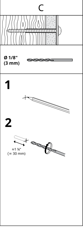
    Illustration for assembly note: Reference panel C for solid wood anchoring, showing screw without plug, required 1/8 in (3 mm) drill bit, marking, and drilling depth approximately 1 1/4 in (30 mm).
  32. Step 23

    The cabinet is positioned against the wall and two top anti-tip brackets are fastened with screws through the wall fitting points.
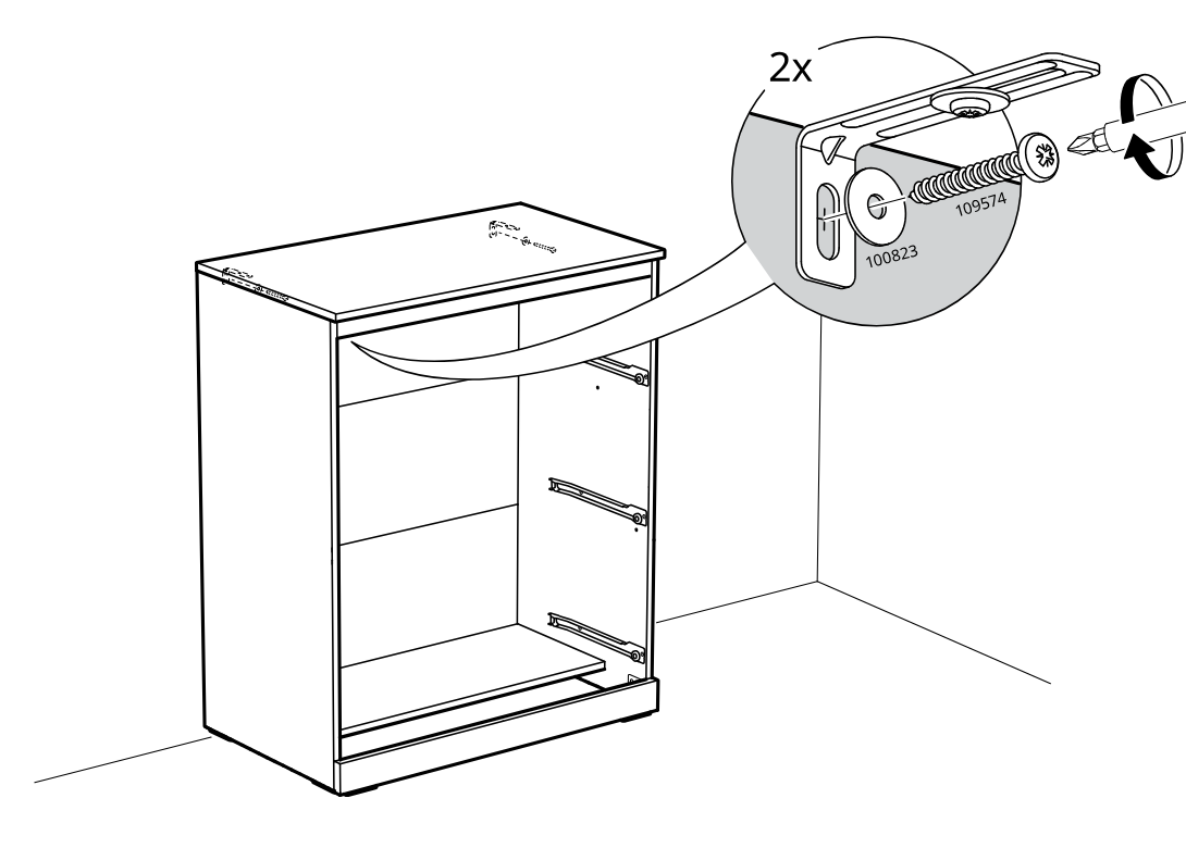
    Diagram for step 23: The cabinet is positioned against the wall and two top anti-tip brackets are fastened with screws through the wall fitting points.
  33. Step 24

    A horizontal stabilizing rail is inserted and hooked into side brackets, then secured by tightening screws on both sides.
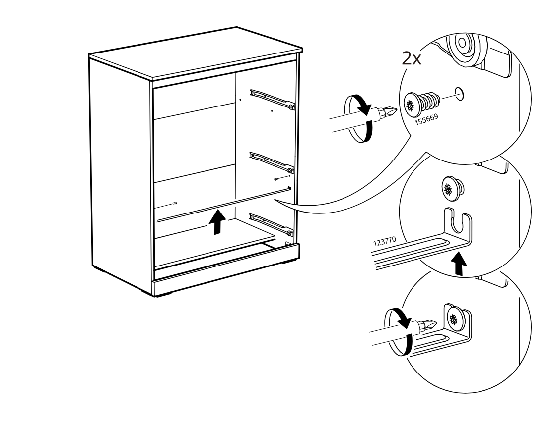
    Diagram for step 24: A horizontal stabilizing rail is inserted and hooked into side brackets, then secured by tightening screws on both sides.
  34. Step 25

    Install four cam screws (118331) into the panel using a screwdriver, as shown in the zoom detail, then align the board with the predrilled holes.
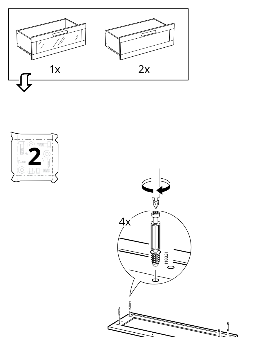
    Diagram for step 25: Install four cam screws (118331) into the panel using a screwdriver, as shown in the zoom detail, then align the board with the predrilled holes.
  35. Step 26

    Insert four dowels (101345) into each side-panel-and-base subassembly layout, shown for mirrored left and right configurations, with a tip-over warning callout included.
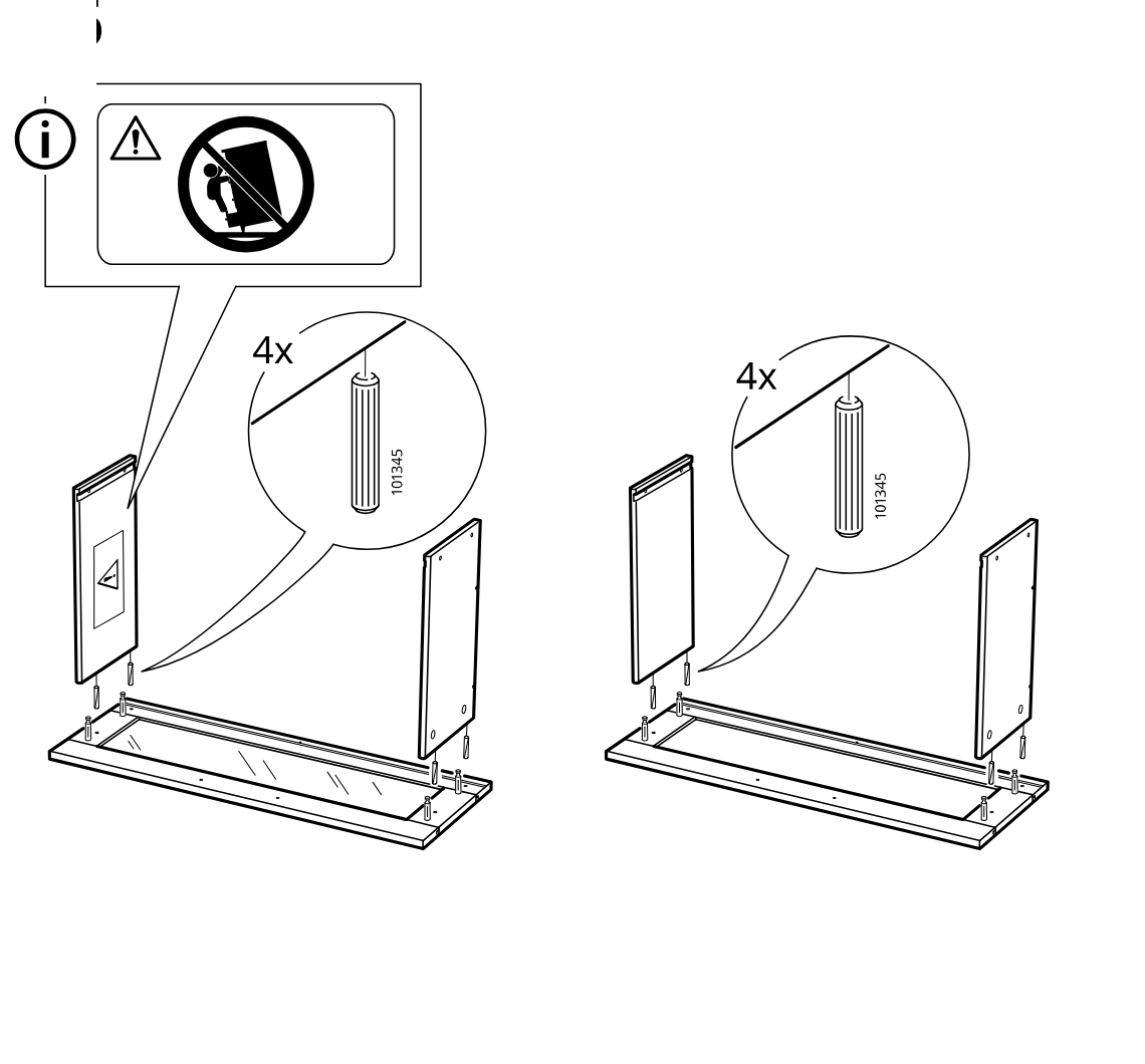
    Diagram for step 26: Insert four dowels (101345) into each side-panel-and-base subassembly layout, shown for mirrored left and right configurations, with a tip-over warning callout included.
  36. Step 27

    Insert and lock four cam fasteners to secure the side panels to the base frame, shown for both product configurations.
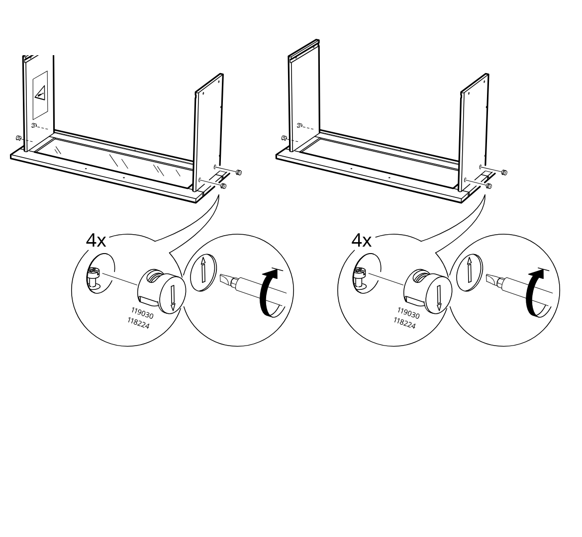
    Diagram for step 27: Insert and lock four cam fasteners to secure the side panels to the base frame, shown for both product configurations.
  37. Step 28

    The back panel is lowered down into the bottom groove between the two side panels.
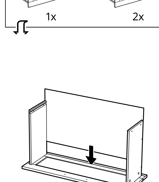
    Diagram for step 28: The back panel is lowered down into the bottom groove between the two side panels.
  38. Step 29

    The top panel is angled in and placed onto the side panels, aligning with the side connection points shown in the inset.
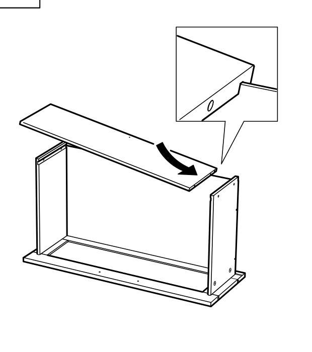
    Diagram for step 29: The top panel is angled in and placed onto the side panels, aligning with the side connection points shown in the inset.
  39. Step 30

    Four screws (110519) are driven into the upper side joints to secure the top panel, using a hammer as illustrated in the callout.
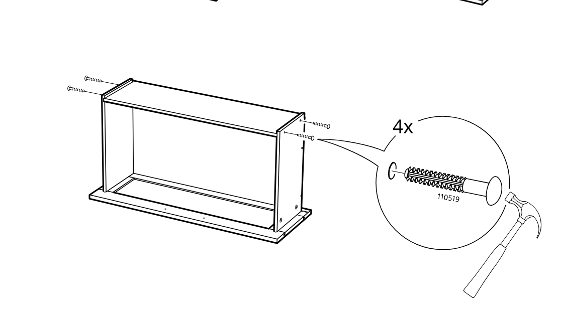
    Diagram for step 30: Four screws (110519) are driven into the upper side joints to secure the top panel, using a hammer as illustrated in the callout.
  40. Step 31

    The frame is positioned upside down and two caps (107091) are pressed into the indicated holes.
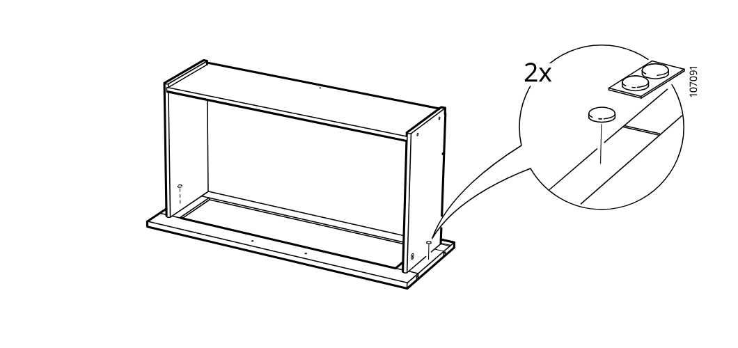
    Diagram for step 31: The frame is positioned upside down and two caps (107091) are pressed into the indicated holes.
  41. Step 32

    Two runner assemblies (10047909/10050507) are inserted downward onto the top edges of the box side panels.
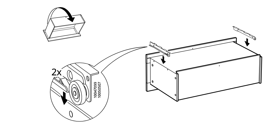
    Diagram for step 32: Two runner assemblies (10047909/10050507) are inserted downward onto the top edges of the box side panels.
  42. Step 33

    Four screws (146114) are driven into the runner brackets, with a note not to use screw type 105344.
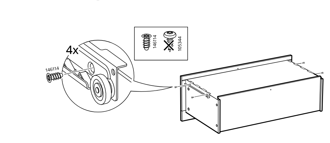
    Diagram for step 33: Four screws (146114) are driven into the runner brackets, with a note not to use screw type 105344.
  43. Step 34

    Attach the rail to the cabinet side using screw 105344 and align the top rail piece as shown.
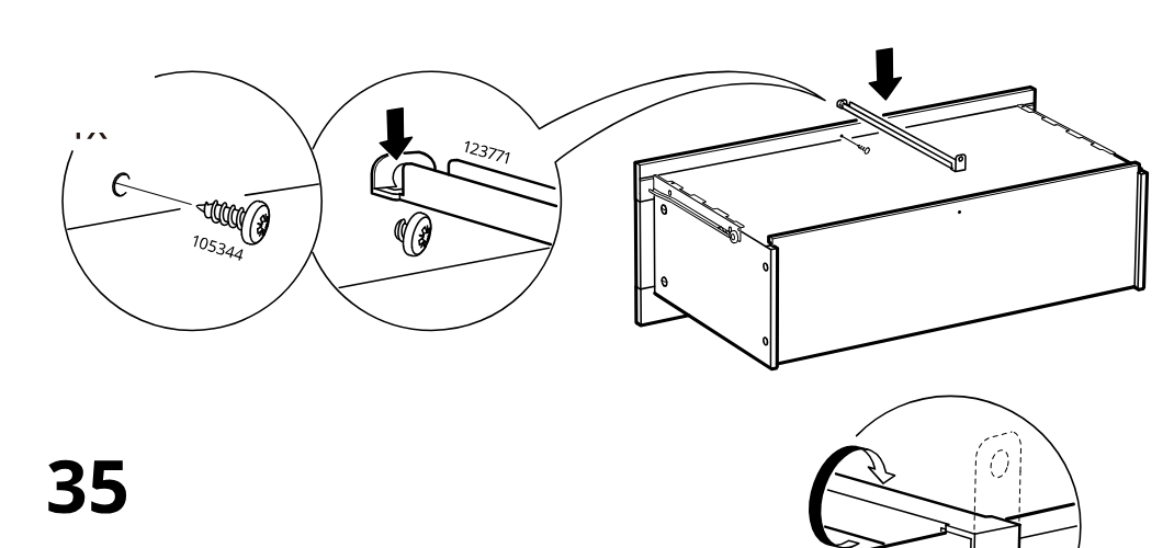
    Diagram for step 34: Attach the rail to the cabinet side using screw 105344 and align the top rail piece as shown.
  44. Step 35

    Position the rail bracket at the cabinet edge and secure it with one 105344 screw.
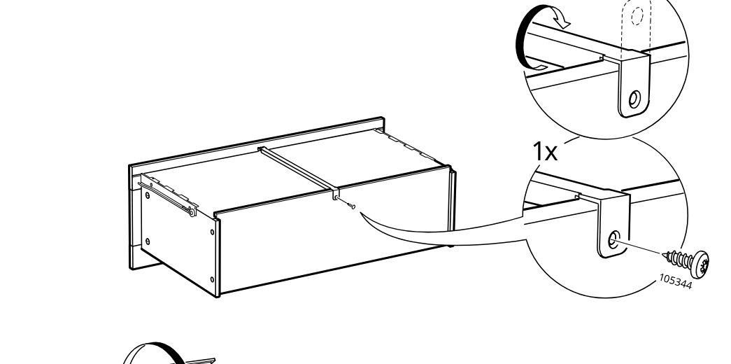
    Diagram for step 35: Position the rail bracket at the cabinet edge and secure it with one 105344 screw.
  45. Step 36

    Rotate the unit, then fasten the drawer front with two 109567 screws and hook the lower edge into place as indicated.
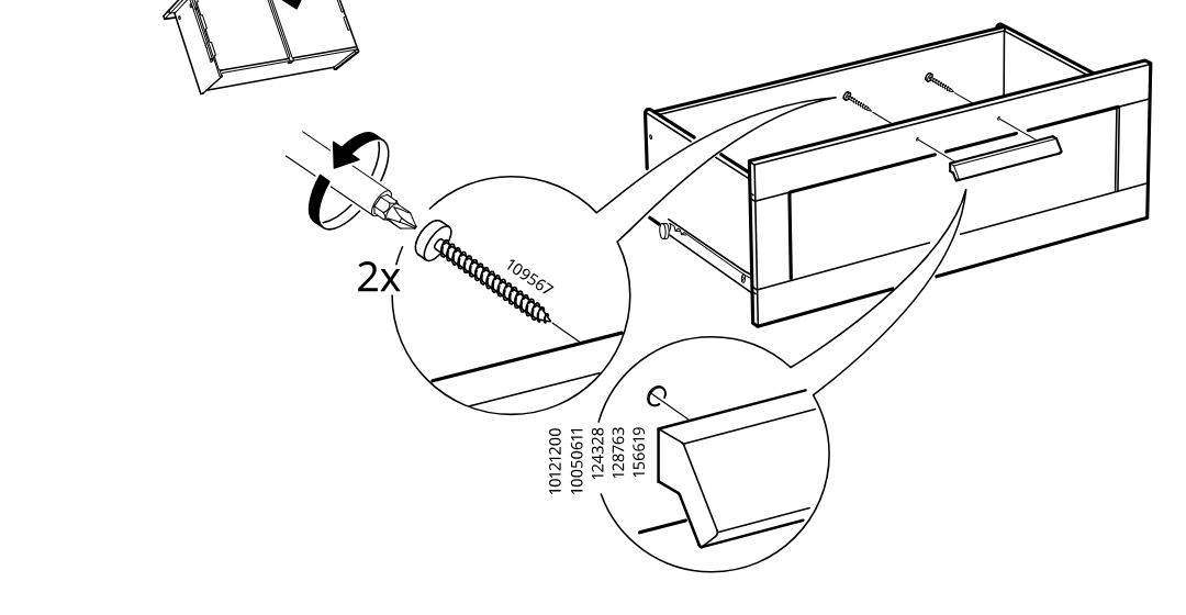
    Diagram for step 36: Rotate the unit, then fasten the drawer front with two 109567 screws and hook the lower edge into place as indicated.

Video guide