How to assemble IKEA HEMNES 6-drawer dresser

HEMNES 6-drawer dresser, white stain, 421/2x515/8"

This guide covers the IKEA HEMNES 6-drawer dresser in white stain, article 005.761.96, measuring 42 1/2 inches wide. Use the dresser diagrams and video for this model.

View on IKEA
HEMNES 6-drawer dresser

Interactive assembly guide

Step-by-Step Instructions

1 different parts, 1 boxes total — click on a package to see step-by-step assembly instructions

HEMNES 6-drawer dresser

005.761.96

x1

21 "

Width

4 ¼ "

Height

52 ¼ "

Length

63 lb 15 oz

Weight

Start Assembly

Written guide

Step-by-step instructions with diagrams

Follow the numbered assembly steps below, or open the interactive guide above to track progress and zoom into each diagram. This guide includes 51 illustrated steps.

HEMNES 6-drawer dresser

  1. Before you begin

    Full-width anti-tip safety warning panel with hazard and prohibition icons plus English, French, and Spanish instructions to secure furniture and prevent tip-over injuries.
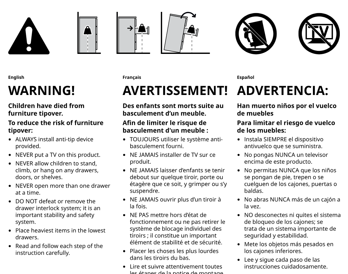
    Illustration for assembly note: Full-width anti-tip safety warning panel with hazard and prohibition icons plus English, French, and Spanish instructions to secure furniture and prevent tip-over injuries.
  2. Before you begin

    Tool and wall-type preparation panel showing required hand tools, drill bits, and correct anchors/screws for masonry, concrete, and wood walls.
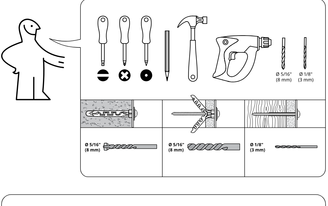
    Illustration for assembly note: Tool and wall-type preparation panel showing required hand tools, drill bits, and correct anchors/screws for masonry, concrete, and wood walls.
  3. Before you begin

    Hardware bag and wall-securing reminder panel indicating anti-tip fastening hardware and securing the unit to the wall.
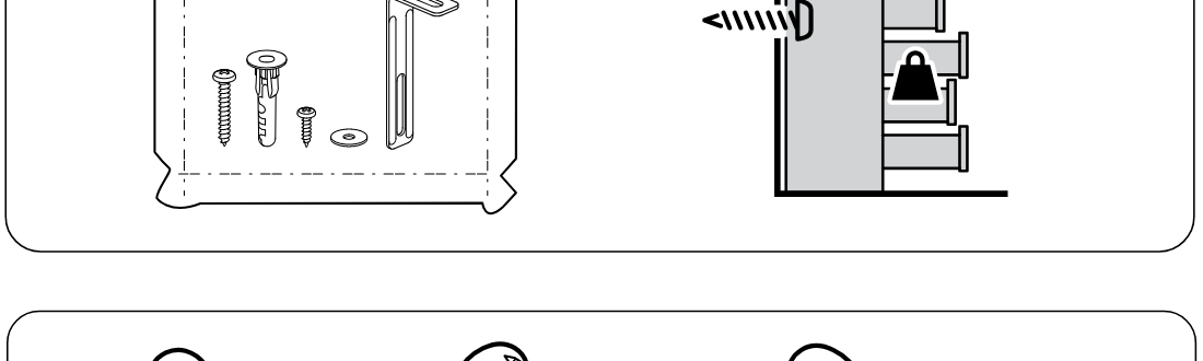
    Illustration for assembly note: Hardware bag and wall-securing reminder panel indicating anti-tip fastening hardware and securing the unit to the wall.
  4. Before you begin

    Safety panel showing two-person assembly required and prohibiting one-person assembly.
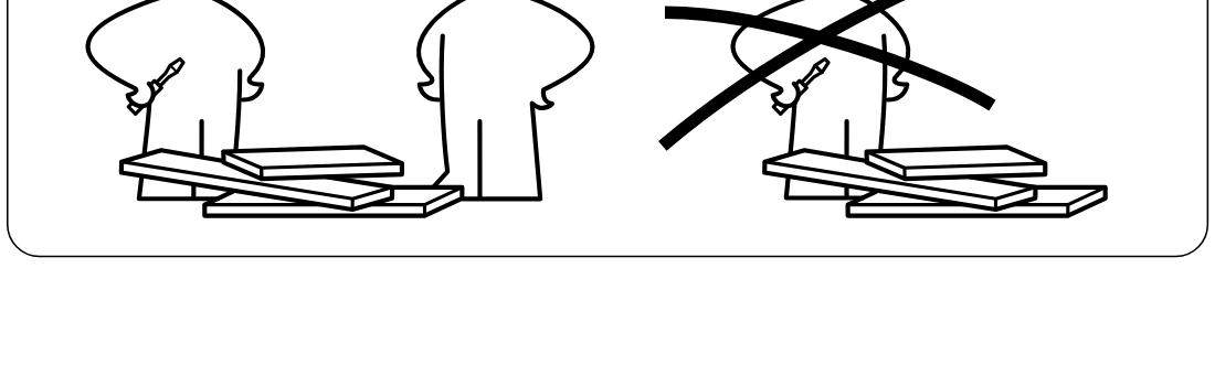
    Illustration for assembly note: Safety panel showing two-person assembly required and prohibiting one-person assembly.
  5. Before you begin

    Parts-bag panel 1 shows required hardware set with item IDs and quantities for bag 1.
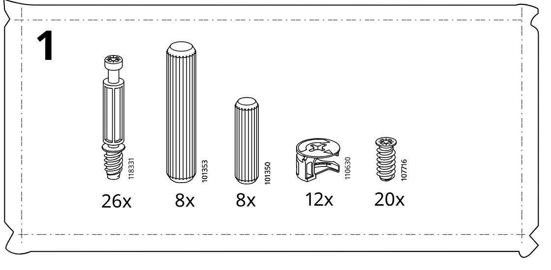
    Illustration for assembly note: Parts-bag panel 1 shows required hardware set with item IDs and quantities for bag 1.
  6. Before you begin

    Parts-bag panel 2 shows required hardware and tools with item IDs and quantities for bag 2.
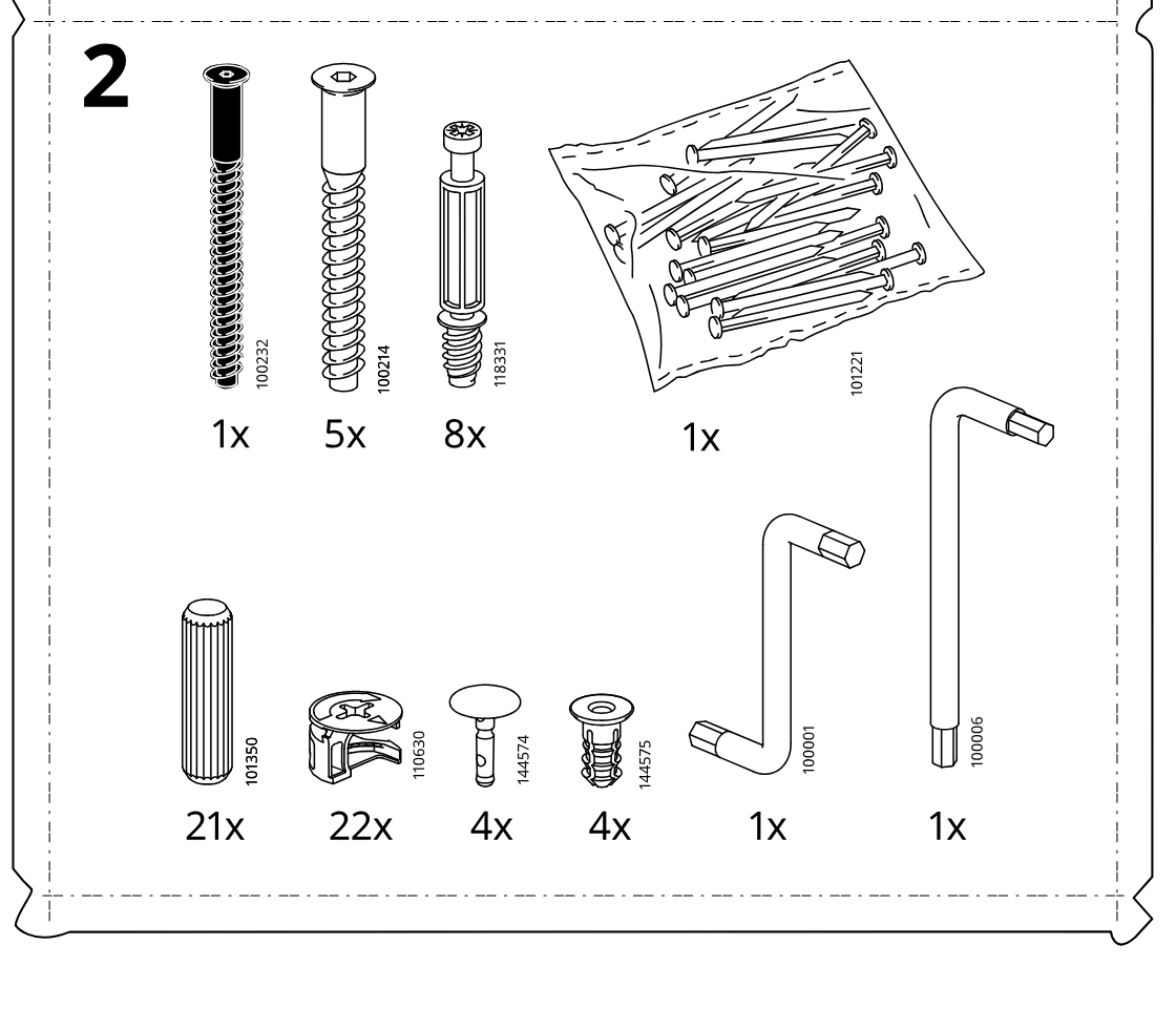
    Illustration for assembly note: Parts-bag panel 2 shows required hardware and tools with item IDs and quantities for bag 2.
  7. Before you begin

    Parts-bag reference panel labeled 3 showing hardware items with quantities: 117615 (12x), 101345 (20x), 119976 (12x), 110519 (26x), 123492 (24x), 110630 (24x), 1008579 (24x), and 105344 (8x).
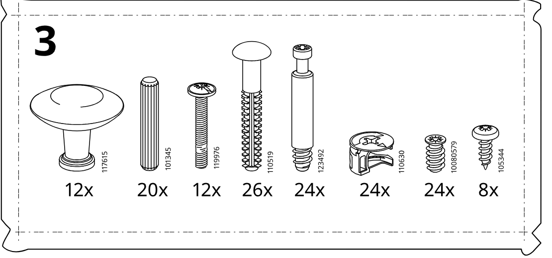
    Illustration for assembly note: Parts-bag reference panel labeled 3 showing hardware items with quantities: 117615 (12x), 101345 (20x), 119976 (12x), 110519 (26x), 123492 (24x), 110630 (24x), 1008579 (24x), and 105344 (8x).
  8. Before you begin

    Standalone parts reference area showing larger components and quantities: 10085261 (5x), 191064/191065 (4x), 10100257 (1x), and 10054446 (4x).
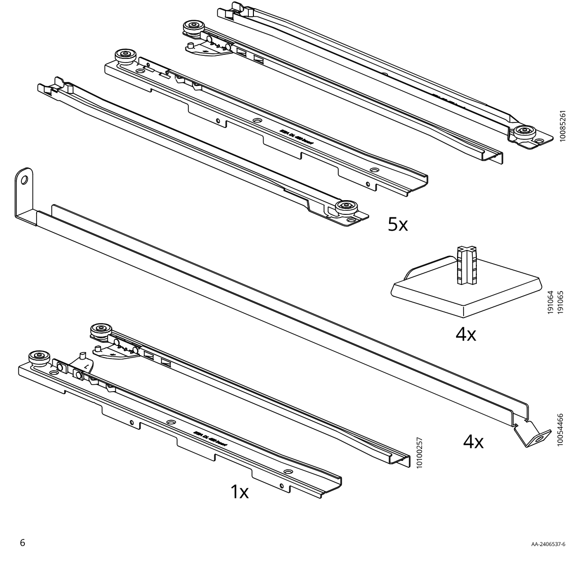
    Illustration for assembly note: Standalone parts reference area showing larger components and quantities: 10085261 (5x), 191064/191065 (4x), 10100257 (1x), and 10054446 (4x).
  9. Step 1

    The four long rails are laid out in orientation L1, L2, R2, and R1, then 12 cam screws (118331) are installed with a screwdriver while following the shown face-direction and insertion-depth warnings, with hardware taken from bag 1.
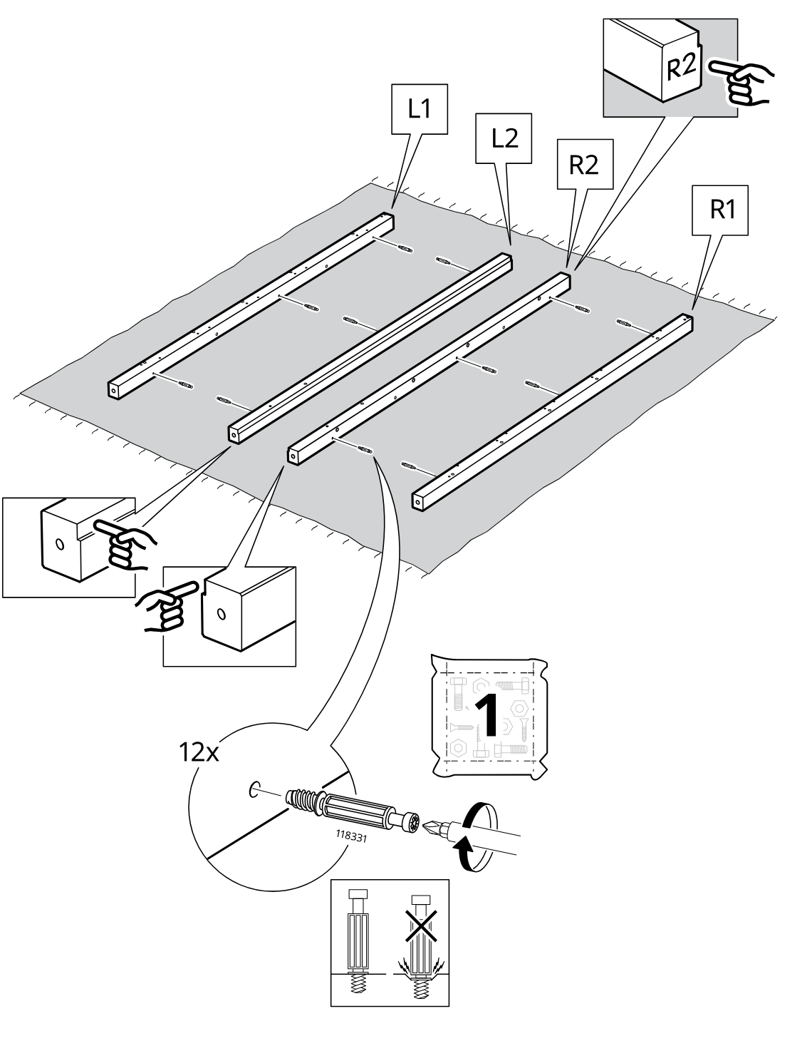
    Diagram for step 1: The four long rails are laid out in orientation L1, L2, R2, and R1, then 12 cam screws (118331) are installed with a screwdriver while following the shown face-direction and insertion-depth warnings, with hardware taken from bag 1.
  10. Step 2

    Two side rails are aligned and slid onto each panel edge with eight 101350 dowels inserted, while an inset note indicates to use dowel 101350 and not 101353.
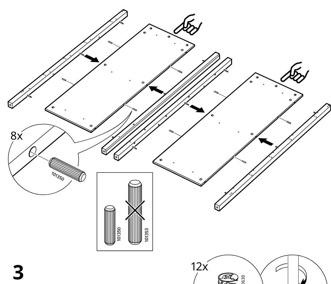
    Diagram for step 2: Two side rails are aligned and slid onto each panel edge with eight 101350 dowels inserted, while an inset note indicates to use dowel 101350 and not 101353.
  11. Step 3

    Twelve cam locks 110630 are inserted into the predrilled holes on the two assembled panel units and tightened as shown in the circular callouts.
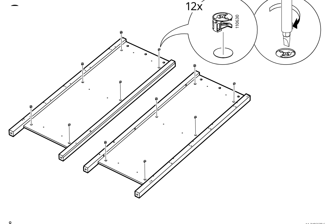
    Diagram for step 3: Twelve cam locks 110630 are inserted into the predrilled holes on the two assembled panel units and tightened as shown in the circular callouts.
  12. Step 4

    The installer inserts eight wooden dowels (101353) into the indicated holes and slides the long center rails in the arrow direction on both mirrored panel assemblies, then engages the small latch clips as shown in the zoomed inset.
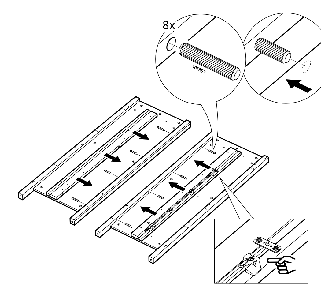
    Diagram for step 4: The installer inserts eight wooden dowels (101353) into the indicated holes and slides the long center rails in the arrow direction on both mirrored panel assemblies, then engages the small latch clips as shown in the zoomed inset.
  13. Step 5

    The panel labeled IKEA CR is assembled by fastening five crossbars with ten screws 107716, with hardware-type exclusions shown in the inline screw comparison box and a zoomed wheel-bracket screw detail.
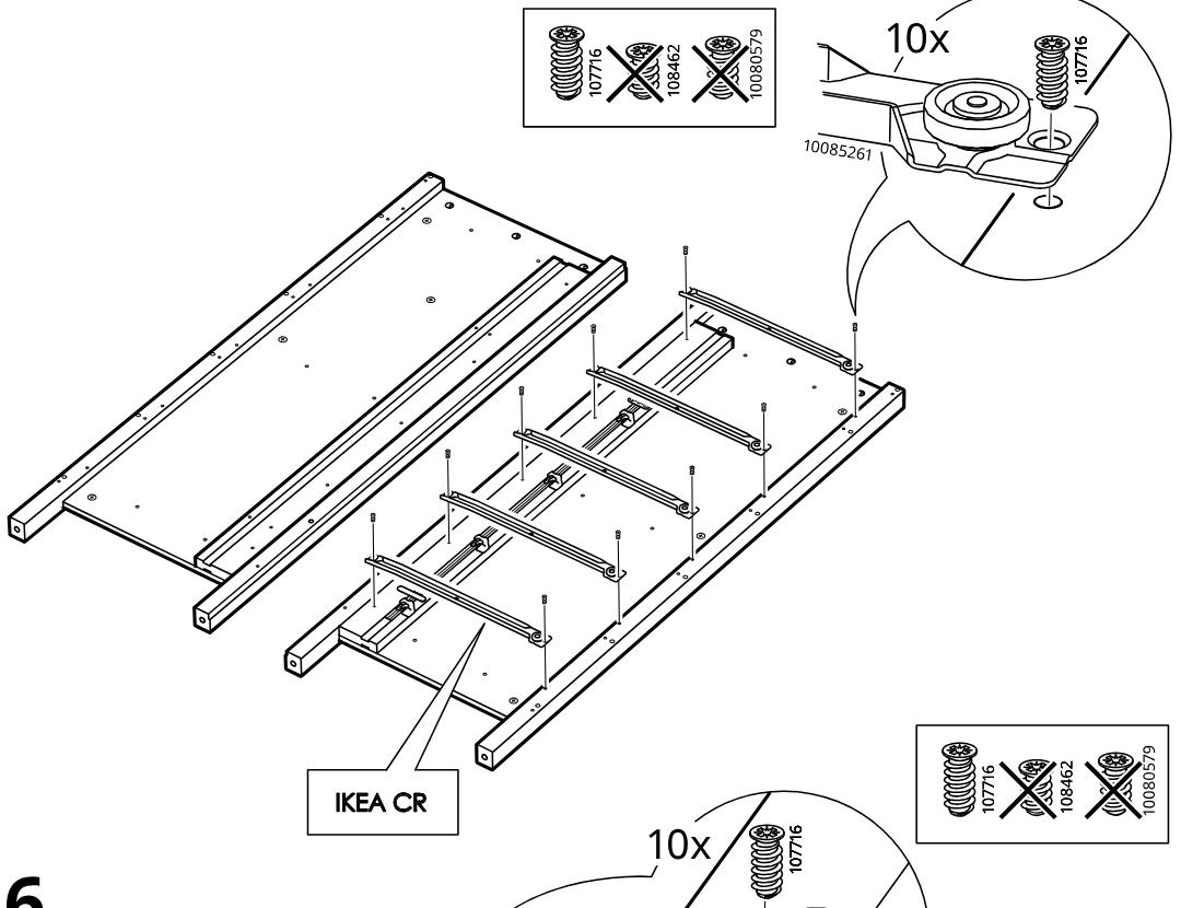
    Diagram for step 5: The panel labeled IKEA CR is assembled by fastening five crossbars with ten screws 107716, with hardware-type exclusions shown in the inline screw comparison box and a zoomed wheel-bracket screw detail.
  14. Step 6

    The panel labeled IKEA CL is assembled similarly by fastening five crossbars with ten screws 107716, shown with a zoomed wheel-bracket screw detail and inline screw comparison box, while the completed opposite panel is shown alongside.
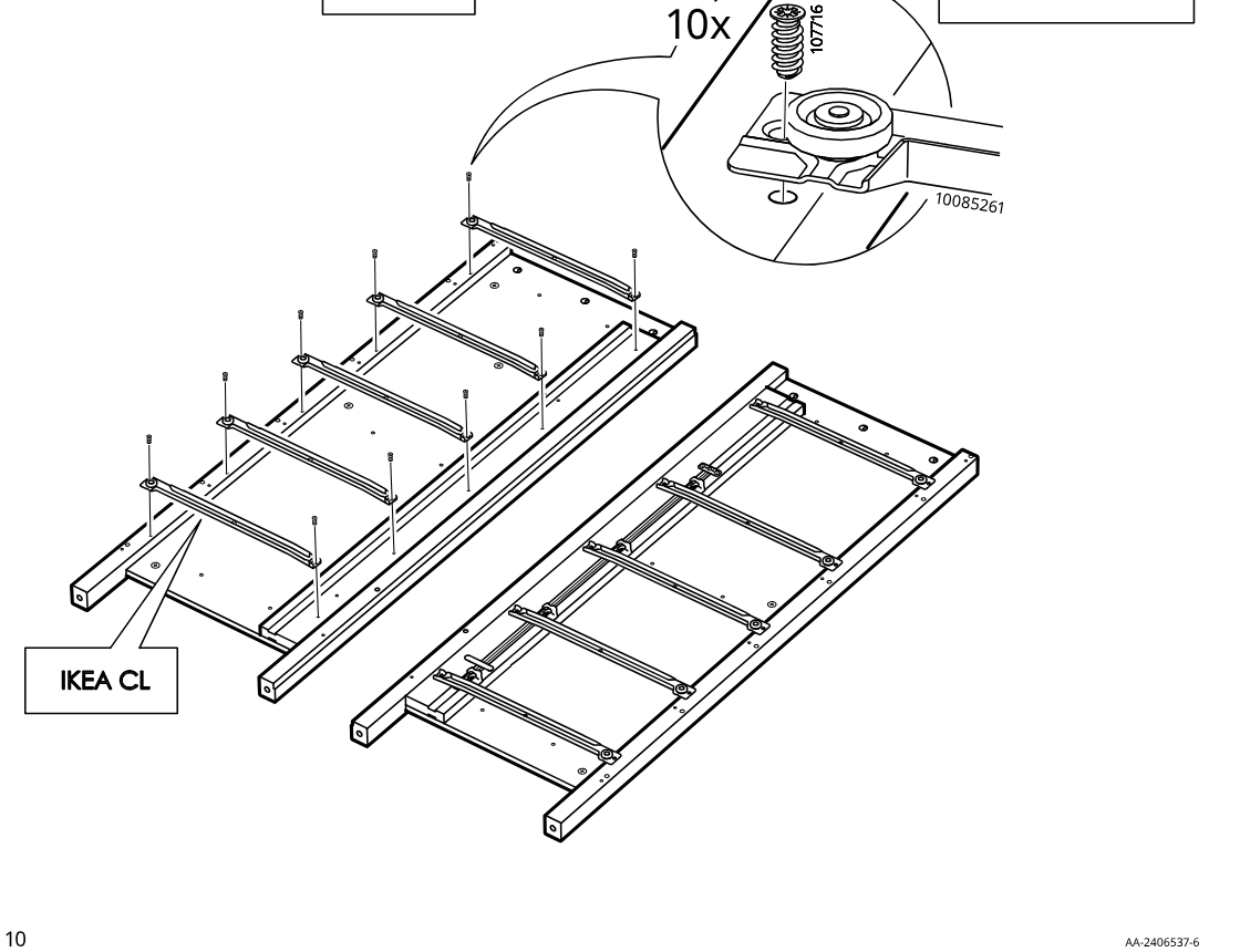
    Diagram for step 6: The panel labeled IKEA CL is assembled similarly by fastening five crossbars with ten screws 107716, shown with a zoomed wheel-bracket screw detail and inline screw comparison box, while the completed opposite panel is shown alongside.
  15. Step 7

    The installer presses two cover pieces (part numbers 191064/191065) onto the open rail ends on both frame assemblies, two per side.
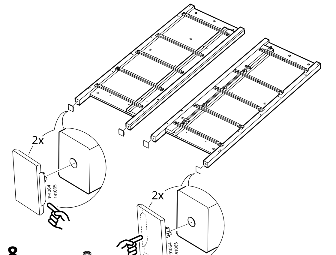
    Diagram for step 7: The installer presses two cover pieces (part numbers 191064/191065) onto the open rail ends on both frame assemblies, two per side.
  16. Step 8

    Fourteen cam screws (118331) are inserted upright into the marked holes across both frame assemblies, with the inset indicating correct insertion orientation.
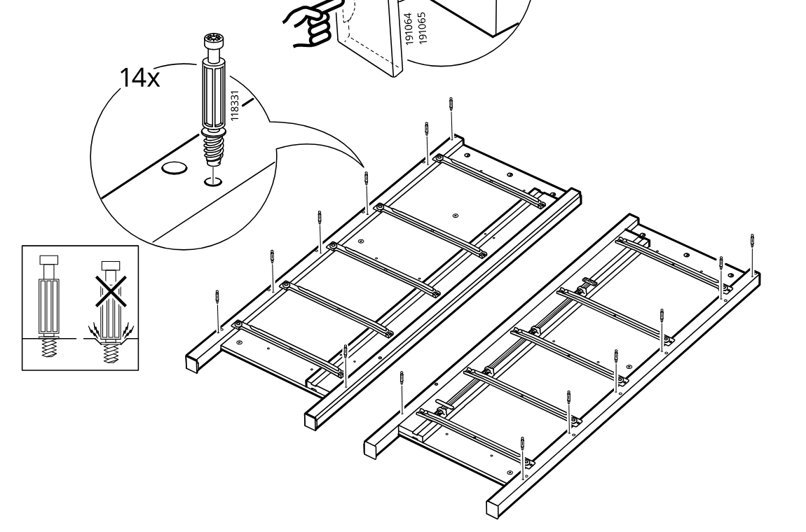
    Diagram for step 8: Fourteen cam screws (118331) are inserted upright into the marked holes across both frame assemblies, with the inset indicating correct insertion orientation.
  17. Step 9

    The installer inserts fourteen wooden dowels (101350) into the predrilled holes of the long rails and panel parts, as indicated by the hardware bag callout and zoom detail.
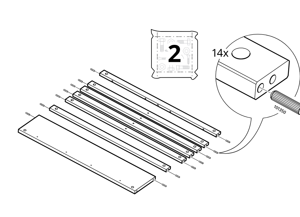
    Diagram for step 9: The installer inserts fourteen wooden dowels (101350) into the predrilled holes of the long rails and panel parts, as indicated by the hardware bag callout and zoom detail.
  18. Step 10

    The two panel assemblies are positioned side by side and a long upright piece is oriented and pressed downward onto the exposed dowels at the right side.
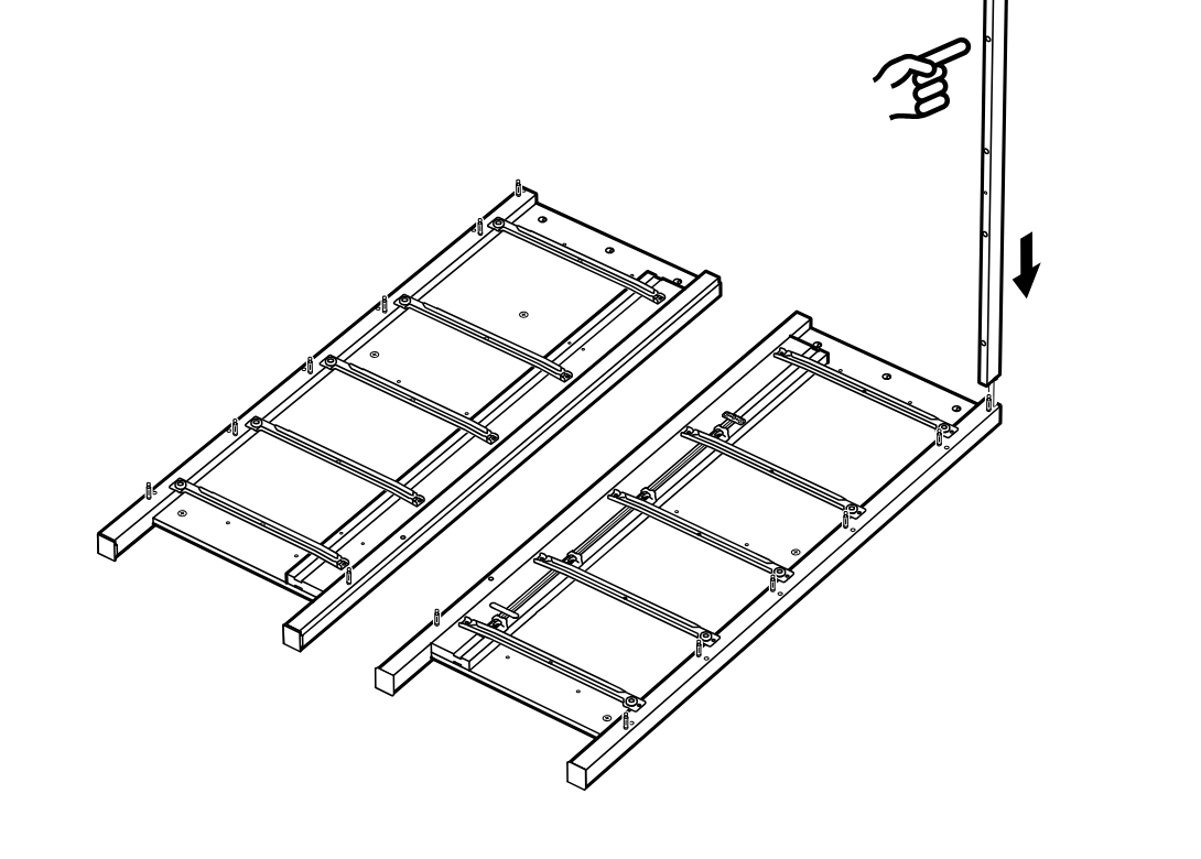
    Diagram for step 10: The two panel assemblies are positioned side by side and a long upright piece is oriented and pressed downward onto the exposed dowels at the right side.
  19. Step 11

    The frame is laid on its side and multiple upright posts are inserted downward into the predrilled positions along the side rail.
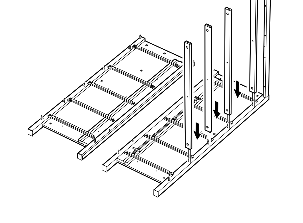
    Diagram for step 11: The frame is laid on its side and multiple upright posts are inserted downward into the predrilled positions along the side rail.
  20. Step 12

    An additional upright post is lowered into the remaining slot so all vertical posts are installed along the rail.
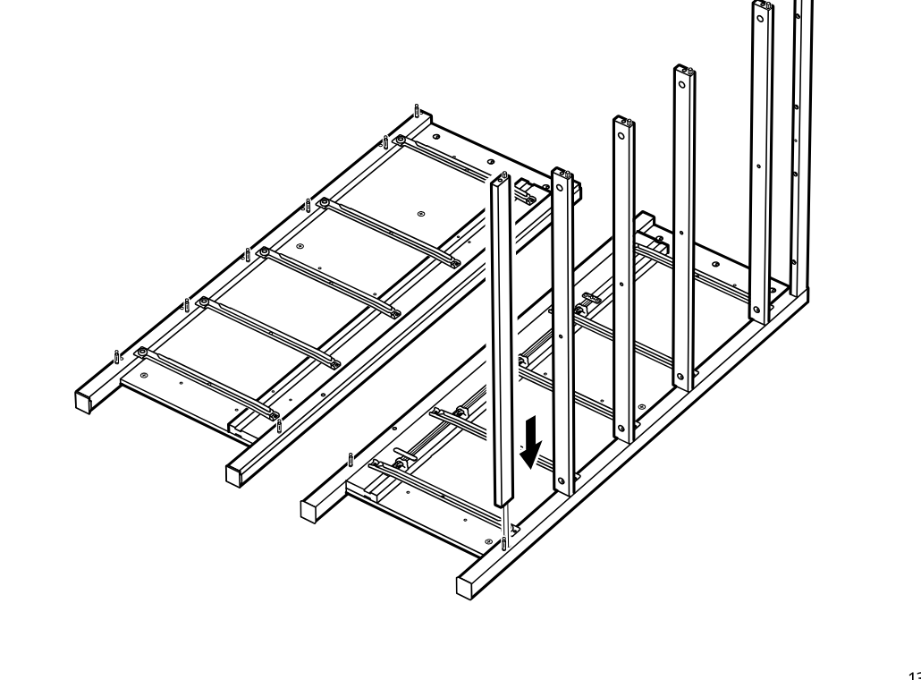
    Diagram for step 12: An additional upright post is lowered into the remaining slot so all vertical posts are installed along the rail.
  21. Step 13

    The frame is assembled with upright side posts and cam locks, then the cams are tightened with a screwdriver as shown in the zoom callout.
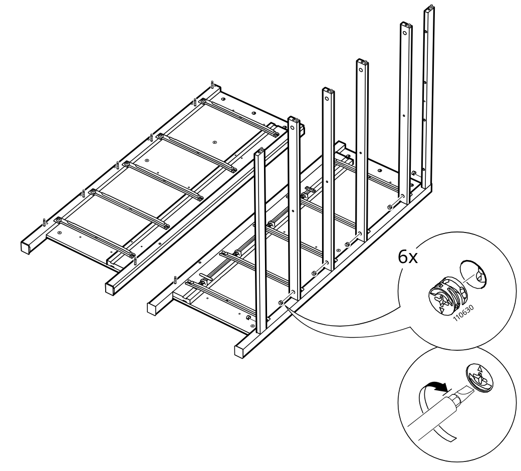
    Diagram for step 13: The frame is assembled with upright side posts and cam locks, then the cams are tightened with a screwdriver as shown in the zoom callout.
  22. Step 14

    One tall side panel is positioned upright onto the frame and aligned with the predrilled holes.
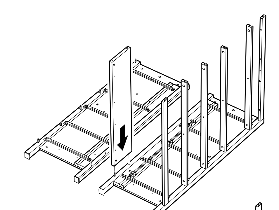
    Diagram for step 14: One tall side panel is positioned upright onto the frame and aligned with the predrilled holes.
  23. Step 15

    The side panel is secured to the frame with one cam lock, then tightened as shown in the two zoom callouts.
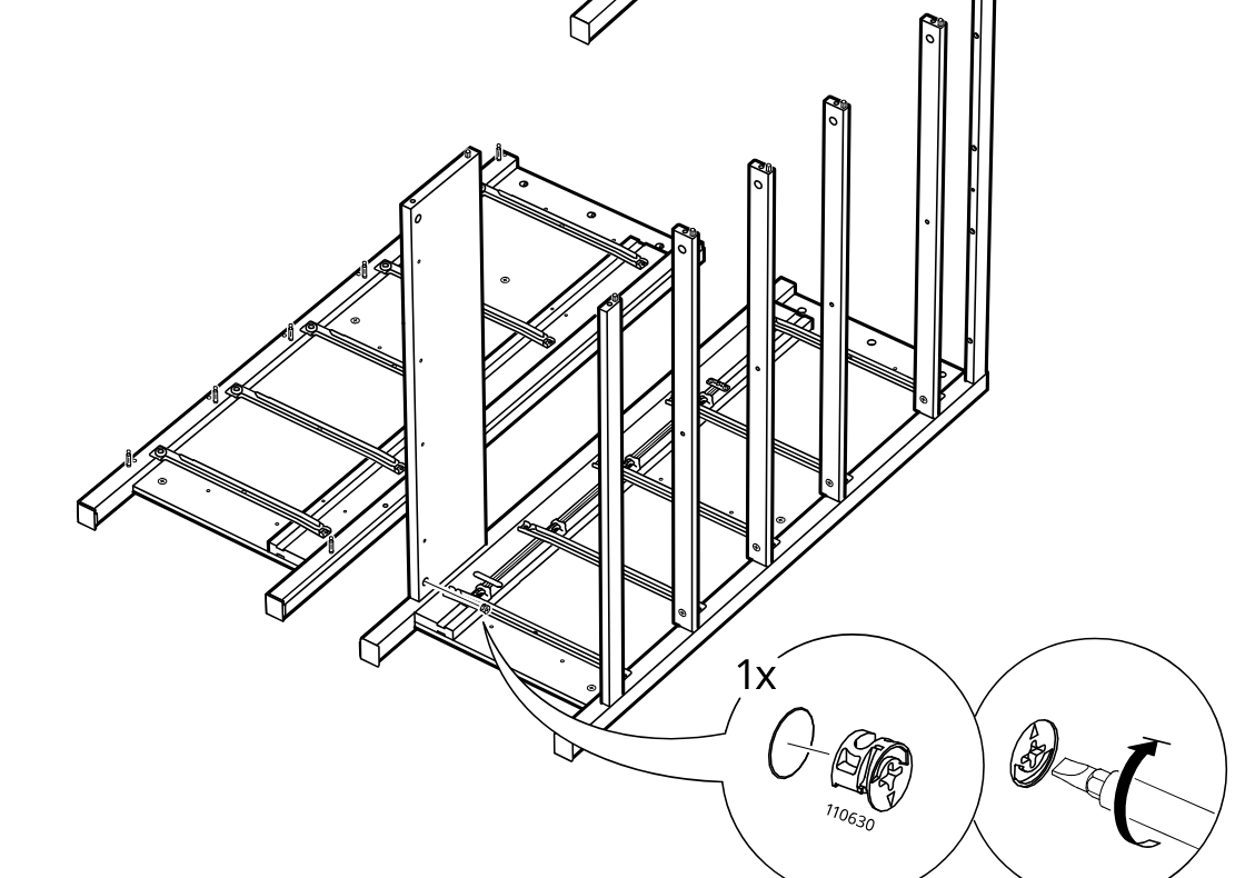
    Diagram for step 15: The side panel is secured to the frame with one cam lock, then tightened as shown in the two zoom callouts.
  24. Step 16

    The side and inner vertical panels are positioned upright on the base frame and aligned beneath the top panel with hardware points indicated.
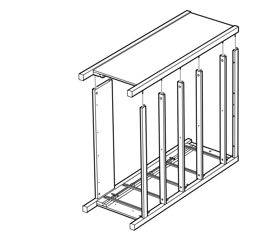
    Diagram for step 16: The side and inner vertical panels are positioned upright on the base frame and aligned beneath the top panel with hardware points indicated.
  25. Step 17

    Seven cam locks (110630) are inserted and tightened with a screwdriver along the upper rail and panel connections, as shown in the zoom callouts.
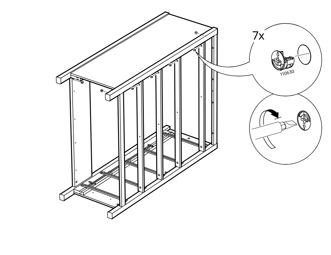
    Diagram for step 17: Seven cam locks (110630) are inserted and tightened with a screwdriver along the upper rail and panel connections, as shown in the zoom callouts.
  26. Step 18

    Insert one 101350 wooden dowel into the top hole of the side panel, as shown in the zoomed callout.
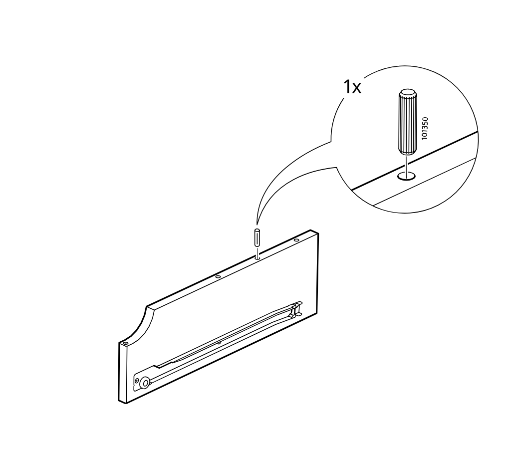
    Diagram for step 18: Insert one 101350 wooden dowel into the top hole of the side panel, as shown in the zoomed callout.
  27. Step 19

    The frame is turned and two different threaded inserts are installed in the indicated top and lower positions using the hex key, with callouts showing which insert type is correct for each location.
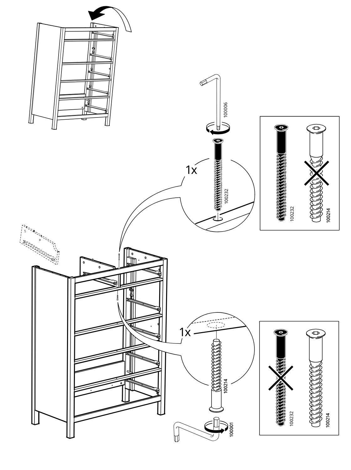
    Diagram for step 19: The frame is turned and two different threaded inserts are installed in the indicated top and lower positions using the hex key, with callouts showing which insert type is correct for each location.
  28. Step 20

    Insert six wooden dowels (101350) into the top holes of the frame, as indicated by the zoom callout.
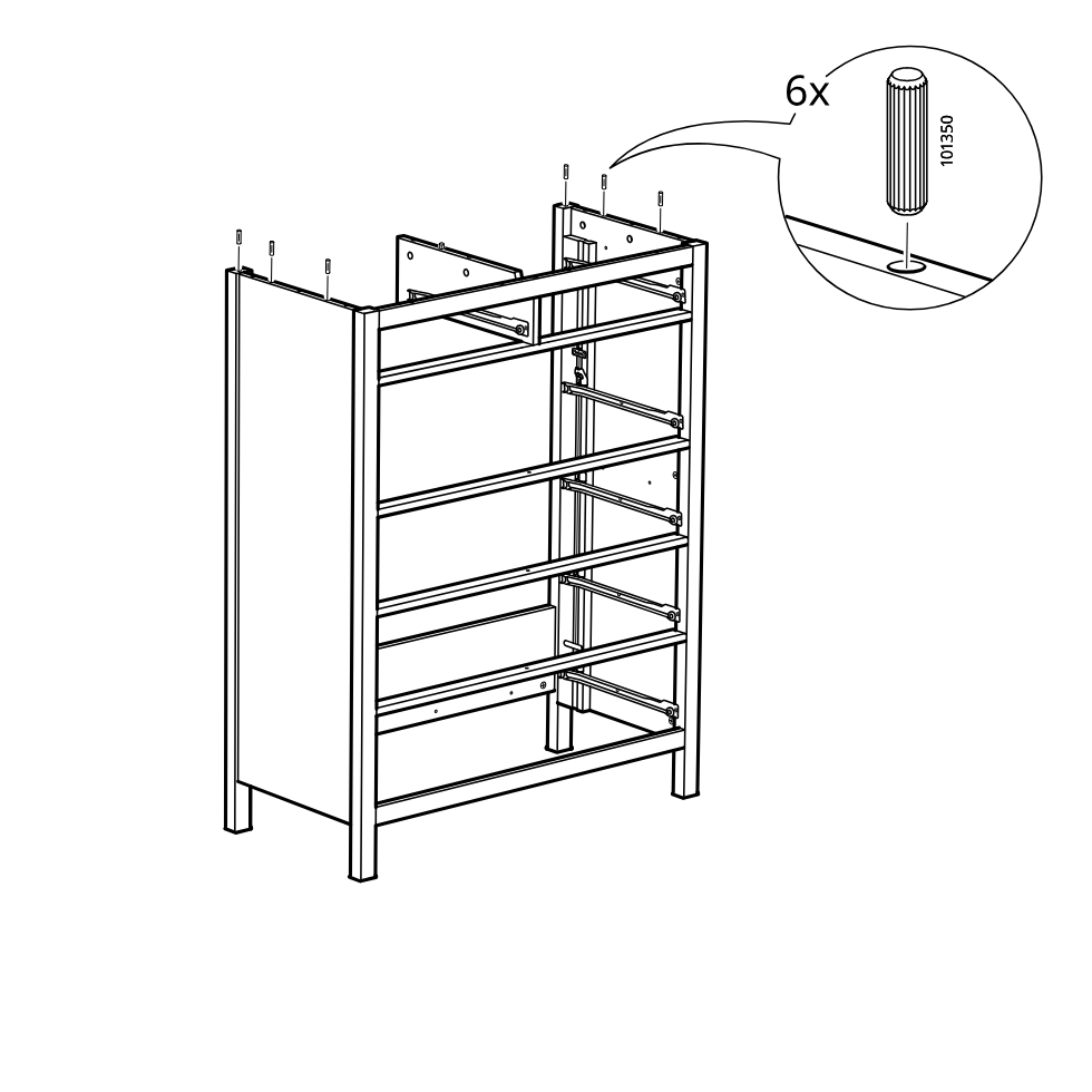
    Diagram for step 20: Insert six wooden dowels (101350) into the top holes of the frame, as indicated by the zoom callout.
  29. Step 21

    The installer positions two metal brackets on the panel edge and screws each bracket in place with a screw and washer set.
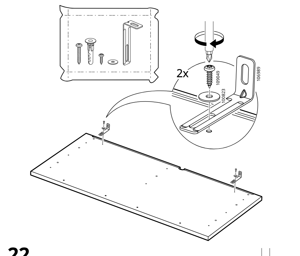
    Diagram for step 21: The installer positions two metal brackets on the panel edge and screws each bracket in place with a screw and washer set.
  30. Step 22

    The installer threads eight dowel bolts into the panel holes, with an inset showing the correct depth/orientation and a crossed-out incorrect example.
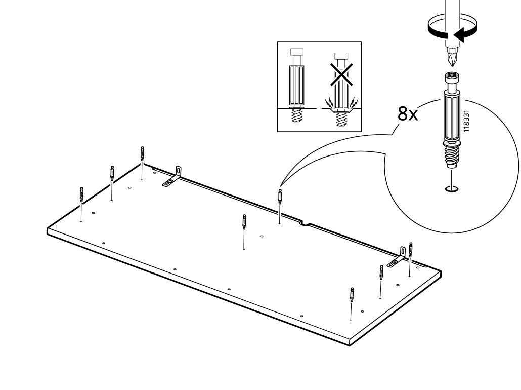
    Diagram for step 22: The installer threads eight dowel bolts into the panel holes, with an inset showing the correct depth/orientation and a crossed-out incorrect example.
  31. Step 23

    The top panel is lowered onto the cabinet frame and aligned with the upper side structures.
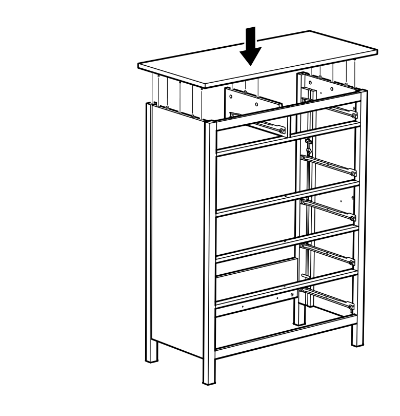
    Diagram for step 23: The top panel is lowered onto the cabinet frame and aligned with the upper side structures.
  32. Step 24

    Four screws (100214) are tightened with the hex key (100001) to secure the top panel to the frame, as shown in the zoom callout.
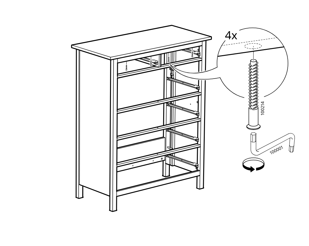
    Diagram for step 24: Four screws (100214) are tightened with the hex key (100001) to secure the top panel to the frame, as shown in the zoom callout.
  33. Step 25

    The frame assembly is shown while eight cam locks (110630) are inserted and tightened with a screwdriver, with zoom callouts indicating placement and turning direction.
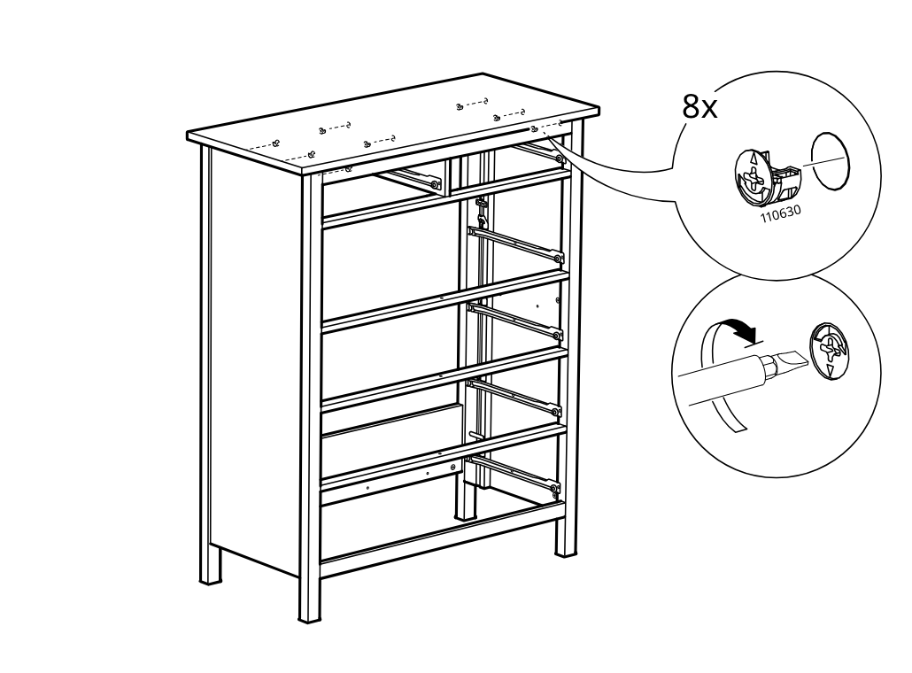
    Diagram for step 25: The frame assembly is shown while eight cam locks (110630) are inserted and tightened with a screwdriver, with zoom callouts indicating placement and turning direction.
  34. Step 26

    The frame is turned and the large panel is slid into position on top of the structure.
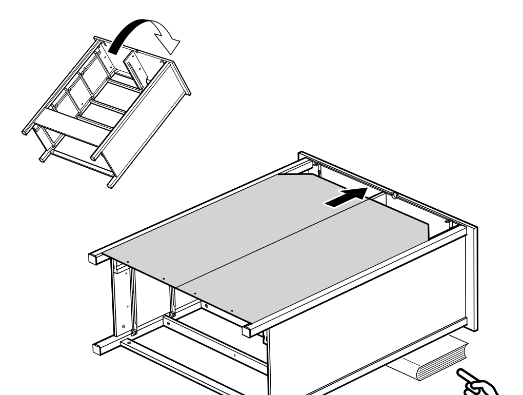
    Diagram for step 26: The frame is turned and the large panel is slid into position on top of the structure.
  35. Step 27

    Four fasteners are inserted through the top panel, as shown in the zoom callout for parts 144575 and 144574.
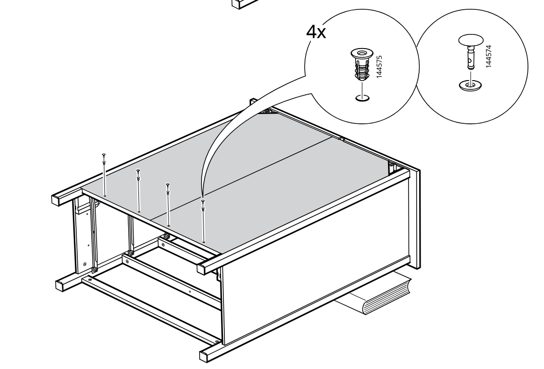
    Diagram for step 27: Four fasteners are inserted through the top panel, as shown in the zoom callout for parts 144575 and 144574.
  36. Step 28

    Hammer one 101221 nail into each top corner while keeping equal distance (X=X) from the edge as shown in the two zoom callouts.
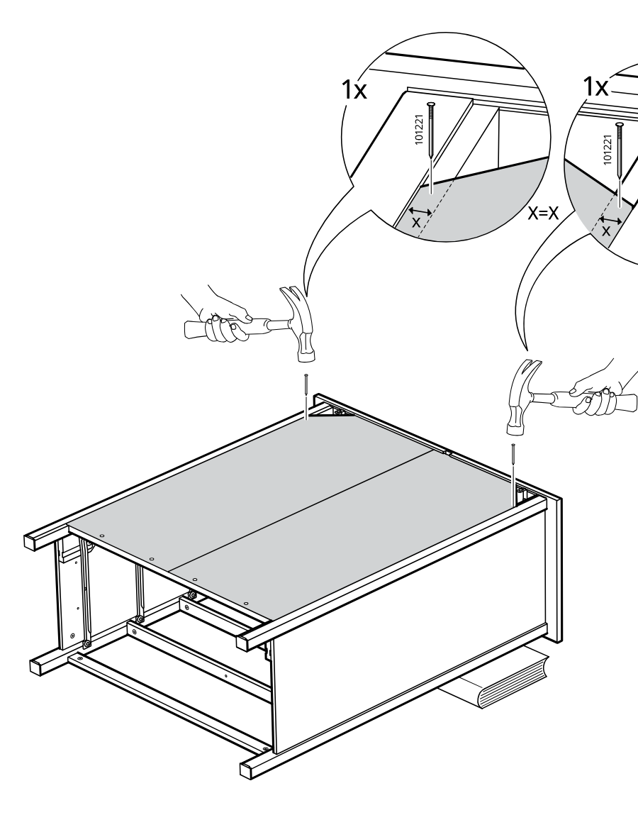
    Diagram for step 28: Hammer one 101221 nail into each top corner while keeping equal distance (X=X) from the edge as shown in the two zoom callouts.
  37. Step 29

    The assembler hammers in 21 nails (part 101221) around the back panel perimeter while the unit is laid on its front, with a zoom callout showing nail placement at the panel edge.
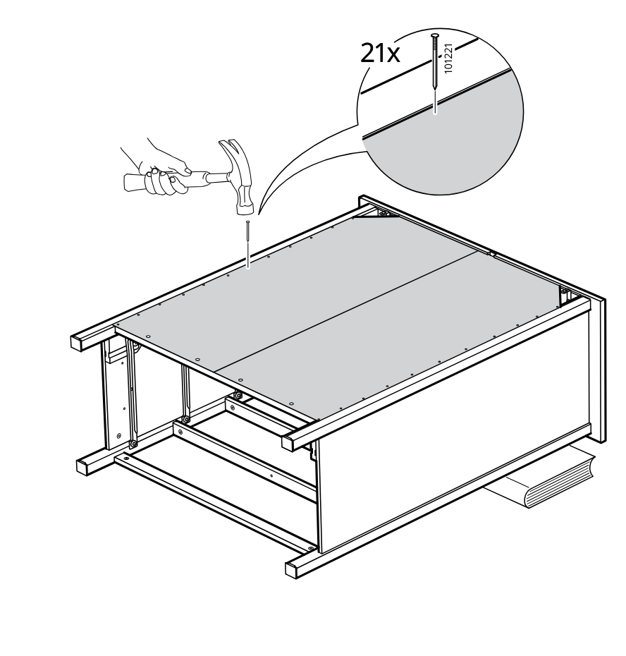
    Diagram for step 29: The assembler hammers in 21 nails (part 101221) around the back panel perimeter while the unit is laid on its front, with a zoom callout showing nail placement at the panel edge.
  38. Step 30

    The assembler installs and tightens two top fasteners on the upper side rails using the shown fitting, then inserts and secures the side piece as indicated by the zoom callouts.
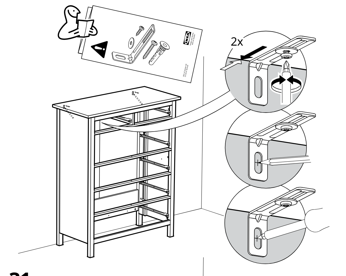
    Diagram for step 30: The assembler installs and tightens two top fasteners on the upper side rails using the shown fitting, then inserts and secures the side piece as indicated by the zoom callouts.
  39. Step 31

    The cabinet frame is shifted sideways in the direction of the arrow to its next position.
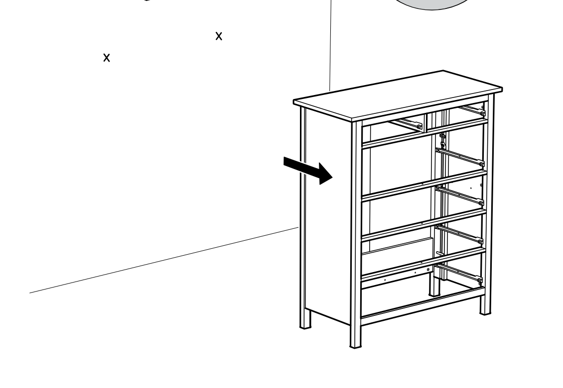
    Diagram for step 31: The cabinet frame is shifted sideways in the direction of the arrow to its next position.
  40. Before you begin

    Top information panel shows secure-it website QR guidance and a wall anchoring reminder icon.

    Illustration for assembly note: Top information panel shows secure-it website QR guidance and a wall anchoring reminder icon.
  41. Before you begin

    Panel A shows instructions for solid wall type A: use Ø 5/16 in (8 mm) drill bit, mark depth, drill about 70 mm, and insert plug with a hammer.
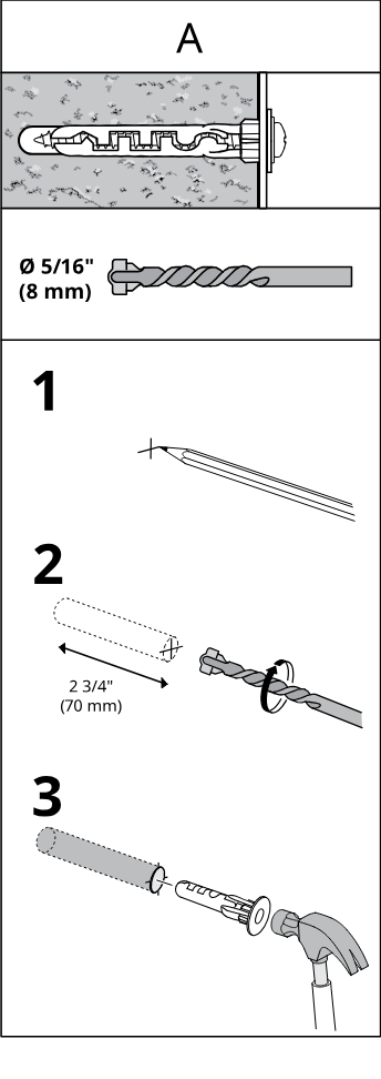
    Illustration for assembly note: Panel A shows instructions for solid wall type A: use Ø 5/16 in (8 mm) drill bit, mark depth, drill about 70 mm, and insert plug with a hammer.
  42. Before you begin

    Panel B shows instructions for hollow wall type B: use Ø 5/16 in (8 mm) drill bit, mark depth, drill about 30 mm, and insert plug with a hammer.
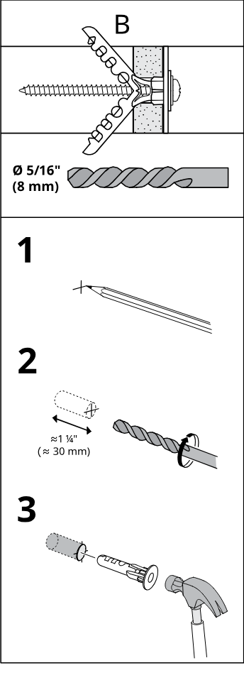
    Illustration for assembly note: Panel B shows instructions for hollow wall type B: use Ø 5/16 in (8 mm) drill bit, mark depth, drill about 30 mm, and insert plug with a hammer.
  43. Before you begin

    Panel C shows instructions for solid wood type C: use Ø 1/8 in (3 mm) drill bit, mark depth, and drill about 30 mm without wall plug.
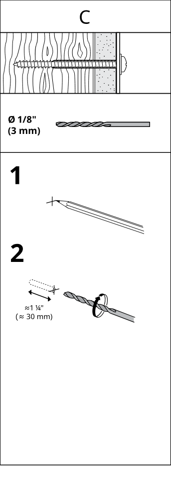
    Illustration for assembly note: Panel C shows instructions for solid wood type C: use Ø 1/8 in (3 mm) drill bit, mark depth, and drill about 30 mm without wall plug.
  44. Step 33

    Secure the anti-tip wall bracket to the wall and cabinet area using two screws, as shown in the zoomed inset.
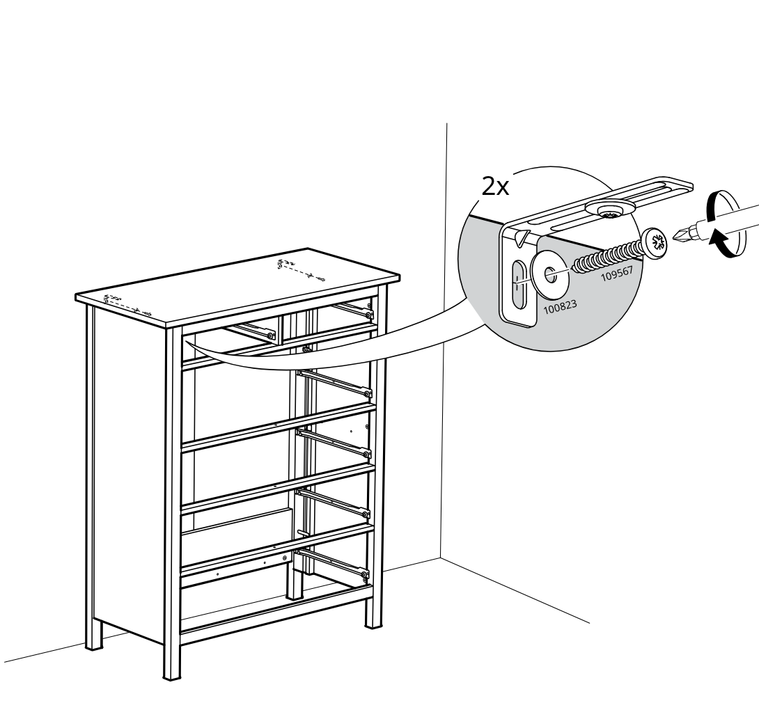
    Diagram for step 33: Secure the anti-tip wall bracket to the wall and cabinet area using two screws, as shown in the zoomed inset.
  45. Step 34

    The user screws four cam bolts (123492) into a long panel using hardware bag 3.
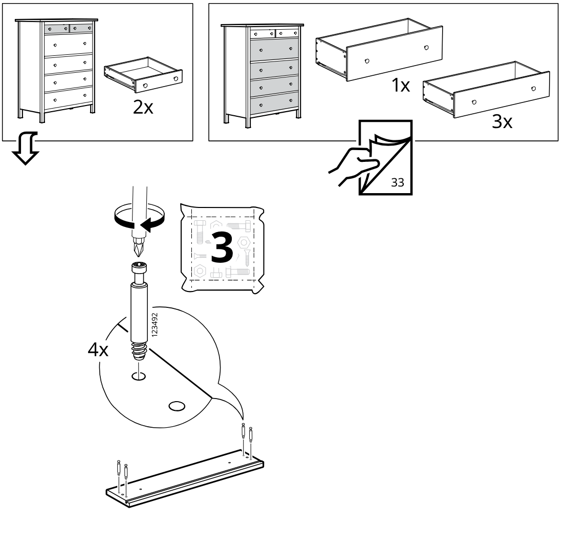
    Diagram for step 34: The user screws four cam bolts (123492) into a long panel using hardware bag 3.
  46. Step 35

    The user inserts two dowels (101345) into the side holes of the two long panels as shown in the zoom callout.
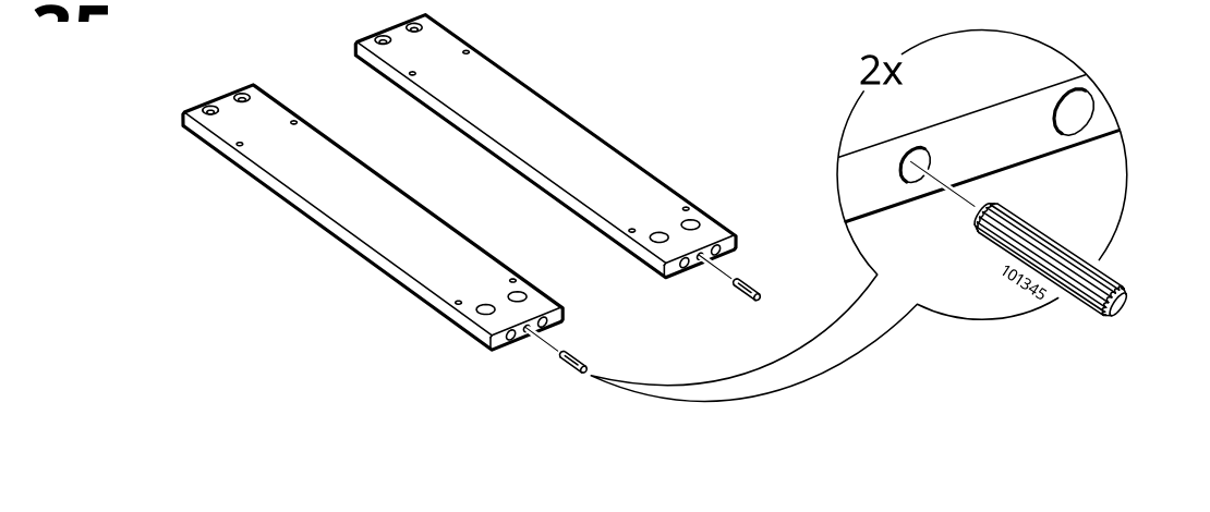
    Diagram for step 35: The user inserts two dowels (101345) into the side holes of the two long panels as shown in the zoom callout.
  47. Step 37

    Insert and lock four cam fittings into the side-panel assembly using the detailed cam-orientation callout.
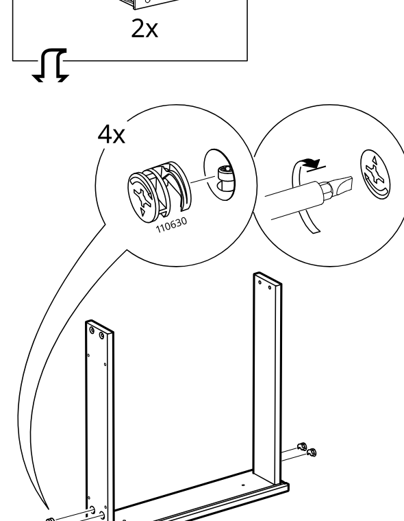
    Diagram for step 37: Insert and lock four cam fittings into the side-panel assembly using the detailed cam-orientation callout.
  48. Step 38

    Lower the large back panel vertically into the base-and-side frame grooves.
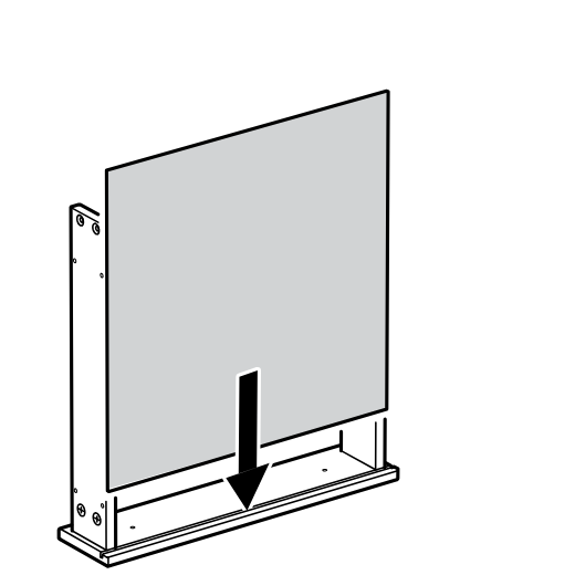
    Diagram for step 38: Lower the large back panel vertically into the base-and-side frame grooves.
  49. Step 39

    Position the top rail on the side panels and secure it with four nails as shown, using the hammer guidance in the zoom callout.
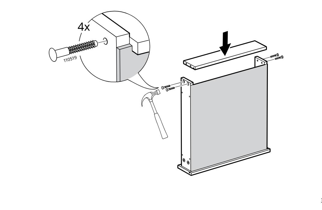
    Diagram for step 39: Position the top rail on the side panels and secure it with four nails as shown, using the hammer guidance in the zoom callout.
  50. Step 40

    Attach and secure the drawer slide wheel assemblies and screws on the drawer sides, with zoom callouts showing the wheel placement and screw fastening (4x).
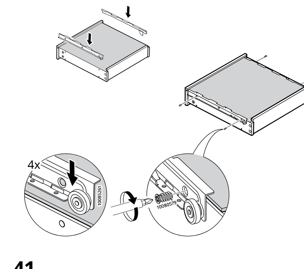
    Diagram for step 40: Attach and secure the drawer slide wheel assemblies and screws on the drawer sides, with zoom callouts showing the wheel placement and screw fastening (4x).
  51. Step 41

    Screw in two long bolts and then press two round knobs onto the drawer side holes, as shown in the enlarged callout.
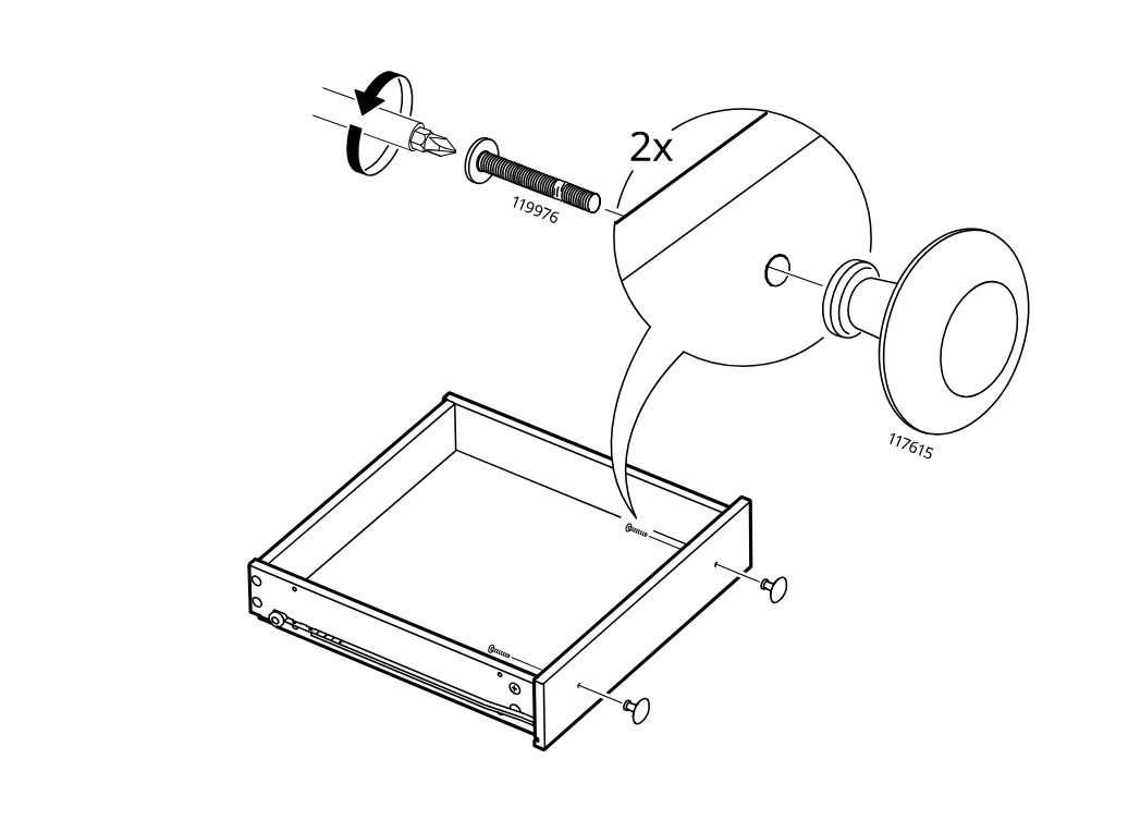
    Diagram for step 41: Screw in two long bolts and then press two round knobs onto the drawer side holes, as shown in the enlarged callout.
  52. Step 42

    Screw four cam bolts (123492) into the panel holes using a screwdriver.
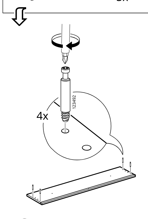
    Diagram for step 42: Screw four cam bolts (123492) into the panel holes using a screwdriver.
  53. Step 43

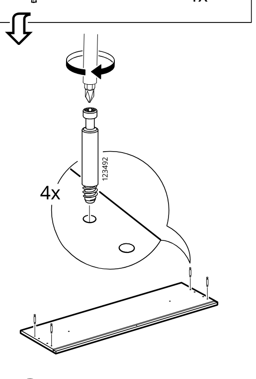
    Screw four cam bolts (123492) into the panel holes using a screwdriver.

    Diagram for step 43: Screw four cam bolts (123492) into the panel holes using a screwdriver.
  54. Step 44

    Insert four ribbed dowels (101345) into the edge holes of the board pair.
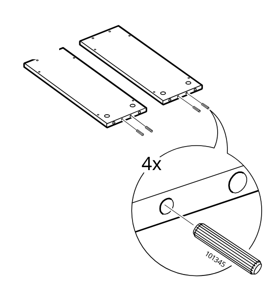
    Diagram for step 44: Insert four ribbed dowels (101345) into the edge holes of the board pair.
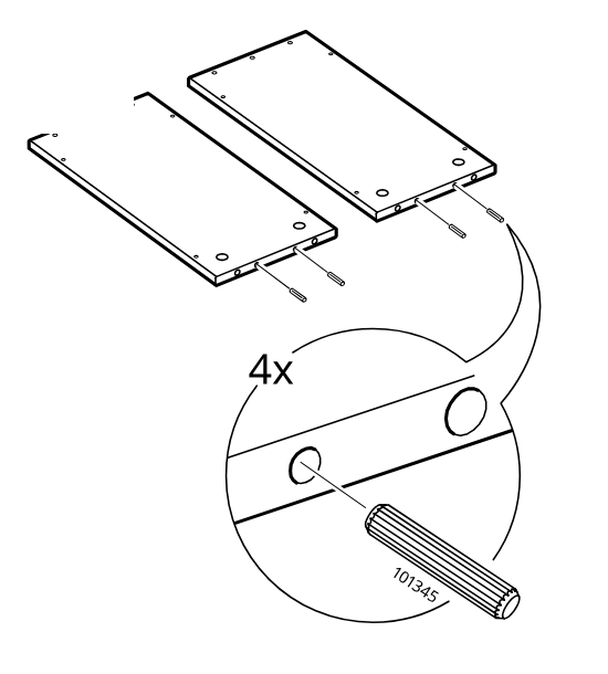
  55. Step 45

    Insert four ribbed dowels (101345) into the edge holes of the board pair.

    Diagram for step 45: Insert four ribbed dowels (101345) into the edge holes of the board pair.
  56. Step 46

    Two side panels are lowered onto the bottom panel with dowels aligned and inserted.
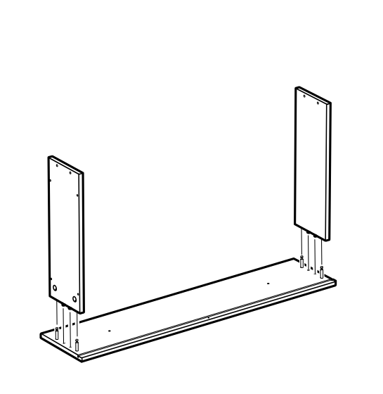
    Diagram for step 46: Two side panels are lowered onto the bottom panel with dowels aligned and inserted.
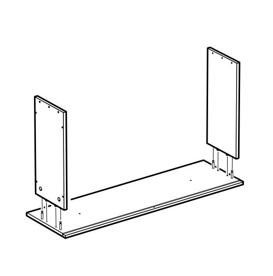
  57. Step 47

    Two side panels are lowered onto the bottom panel with dowels aligned and inserted.

    Diagram for step 47: Two side panels are lowered onto the bottom panel with dowels aligned and inserted.
  58. Step 48

    Four cam locks are inserted and turned with a screwdriver to secure the side panels to the bottom panel.
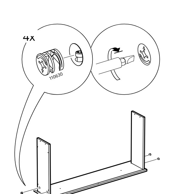
    Diagram for step 48: Four cam locks are inserted and turned with a screwdriver to secure the side panels to the bottom panel.
  59. Step 49

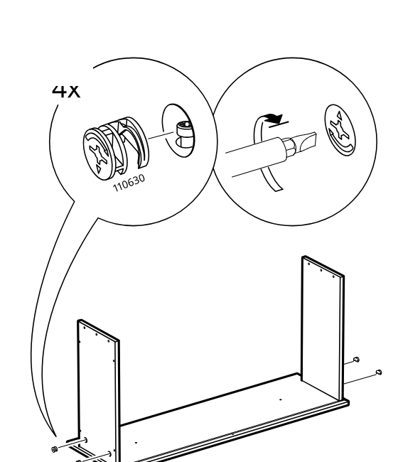
    Four cam locks are inserted and turned with a screwdriver to secure the side panels to the bottom panel.

    Diagram for step 49: Four cam locks are inserted and turned with a screwdriver to secure the side panels to the bottom panel.
  60. Step 50

    The large panel is lowered straight down onto the left-side cabinet frame.
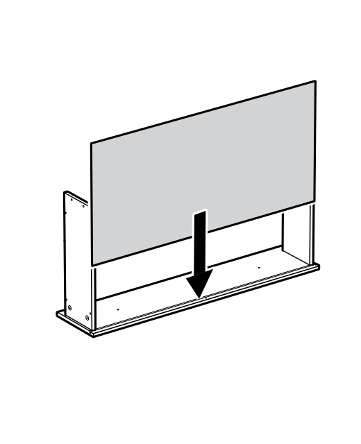
    Diagram for step 50: The large panel is lowered straight down onto the left-side cabinet frame.
  61. Step 51

    The large panel is lowered straight down onto the right-side cabinet frame variant.
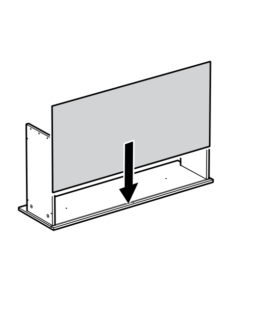
    Diagram for step 51: The large panel is lowered straight down onto the right-side cabinet frame variant.
  62. Step 52

    The top board is positioned and fixed with four 110519 nails while tapping in remaining side fasteners with a hammer.
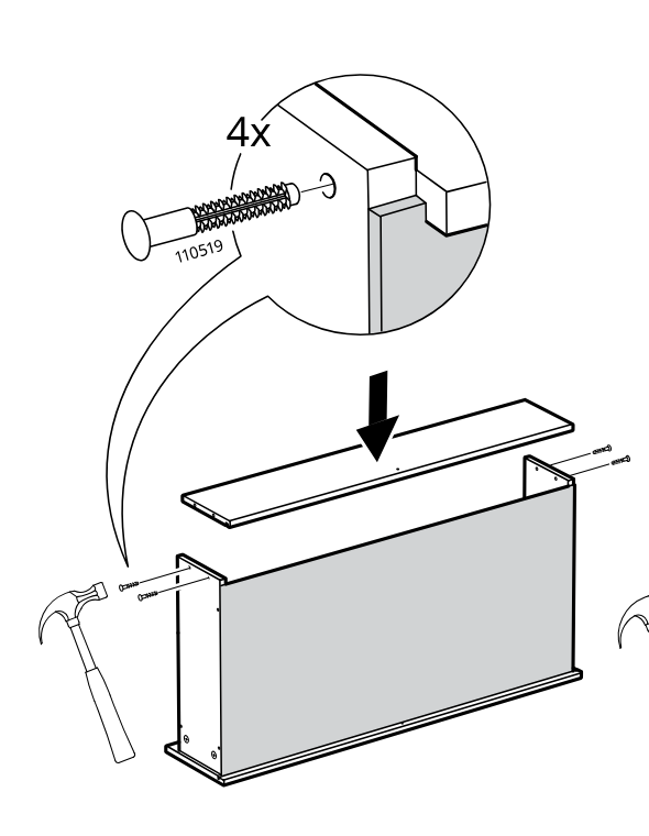
    Diagram for step 52: The top board is positioned and fixed with four 110519 nails while tapping in remaining side fasteners with a hammer.
  63. Step 53

    The top board is positioned and fixed with six 110519 nails for the alternate frame configuration while tapping in side fasteners.
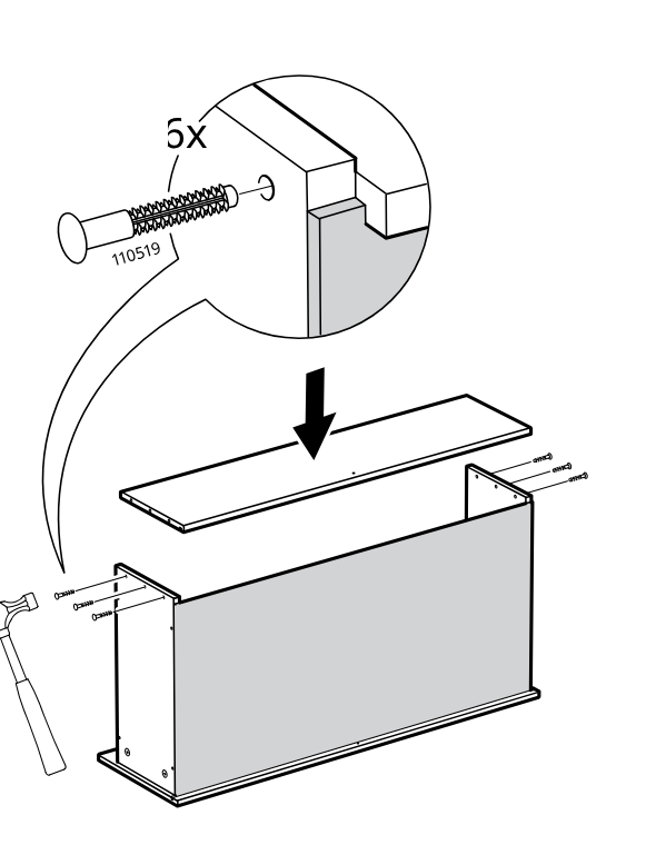
    Diagram for step 53: The top board is positioned and fixed with six 110519 nails for the alternate frame configuration while tapping in side fasteners.

Video guide