How to assemble IKEA HEMNES bed frame

HEMNES bed frame, white stain/Luröy, Queen

This guide covers the IKEA HEMNES Queen bed frame in white stain/LURÖY, combination 990.078.56. Use the HEMNES bed-frame diagrams and video to follow the assembly sequence.

View on IKEA
HEMNES bed frame

Interactive assembly guide

Step-by-Step Instructions

1 different parts, 1 boxes total — click on a package to see step-by-step assembly instructions

HEMNES Bed frame

902.421.13

x1

27 ½ "

Width

2 ¾ "

Height

67 "

Length

53 lb 4 oz

Weight

Start Assembly

Written guide

Step-by-step instructions with diagrams

Follow the numbered assembly steps below, or open the interactive guide above to track progress and zoom into each diagram. This guide includes 29 illustrated steps.

HEMNES Bed frame

  1. Before you begin

    Preparation and safety guidance panels: use the correct screwdriver type, avoid assembling alone and use two people, avoid assembly on hard surfaces and assemble on a soft surface, and consult instructions or contact IKEA support if unsure.
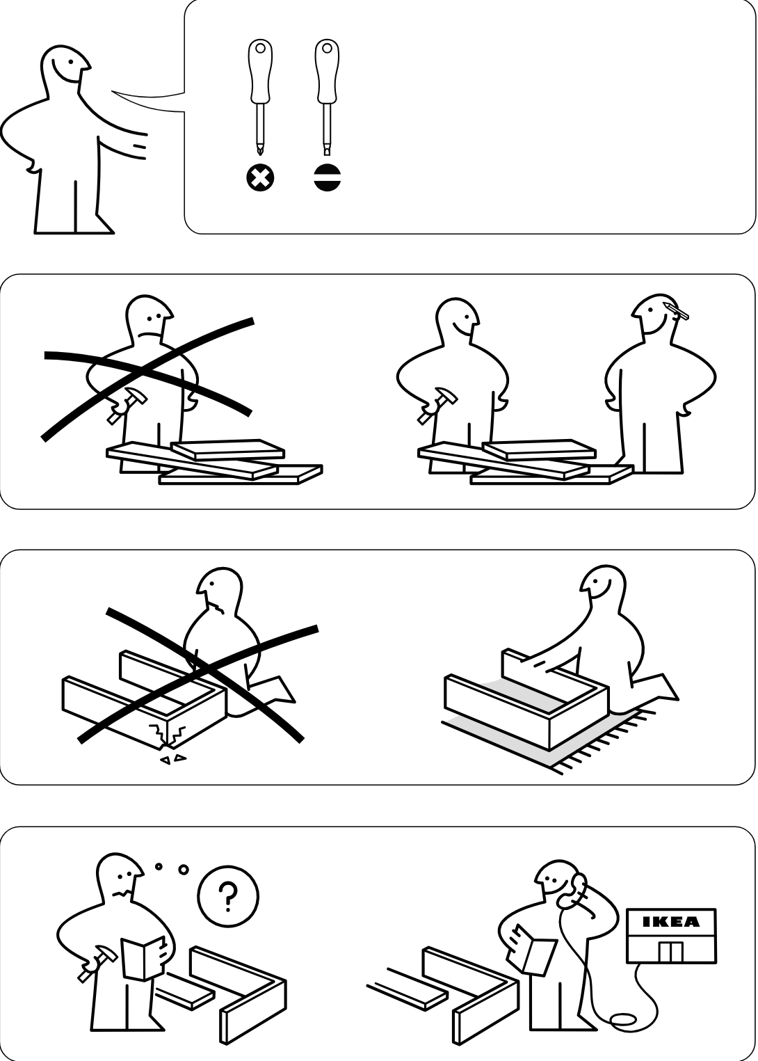
    Illustration for assembly note: Preparation and safety guidance panels: use the correct screwdriver type, avoid assembling alone and use two people, avoid assembly on hard surfaces and assemble on a soft surface, and consult instructions or contact IKEA support if unsure.
  2. Before you begin

    Parts-bag reference panel 1 showing included hardware and tool quantities for step set 1.
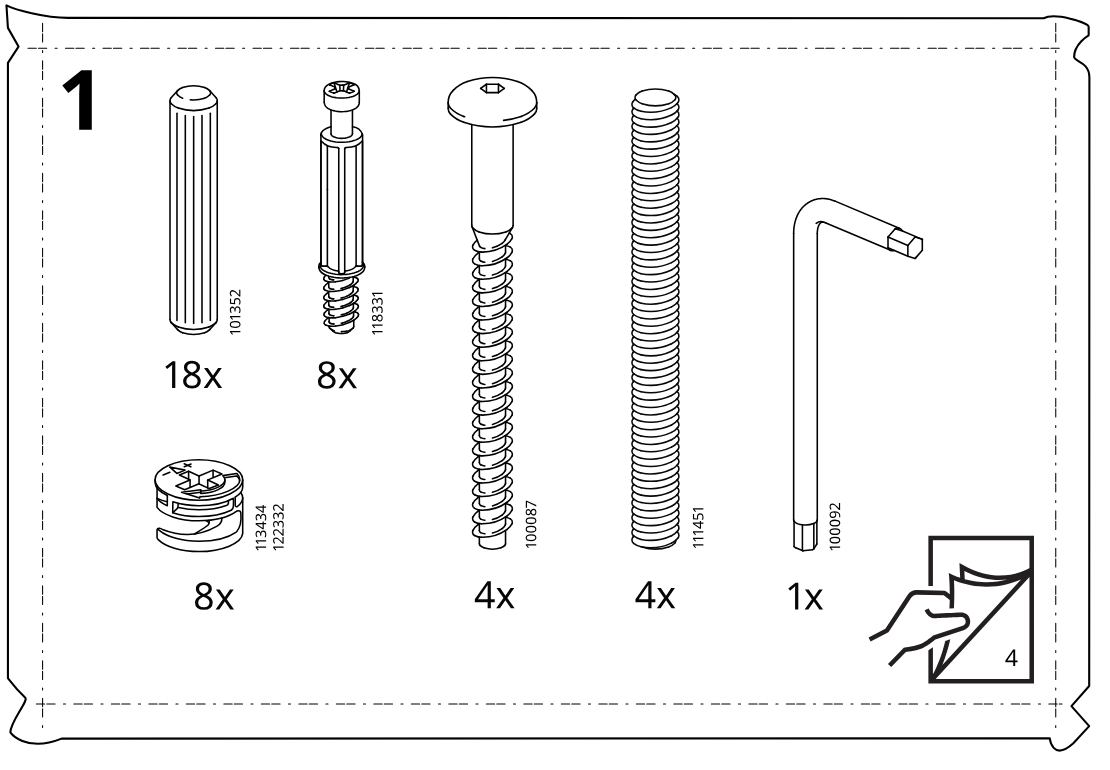
    Illustration for assembly note: Parts-bag reference panel 1 showing included hardware and tool quantities for step set 1.
  3. Before you begin

    Parts-bag reference panel 2 showing included hardware, fittings, wrench, bracket, and quantities for step set 2.
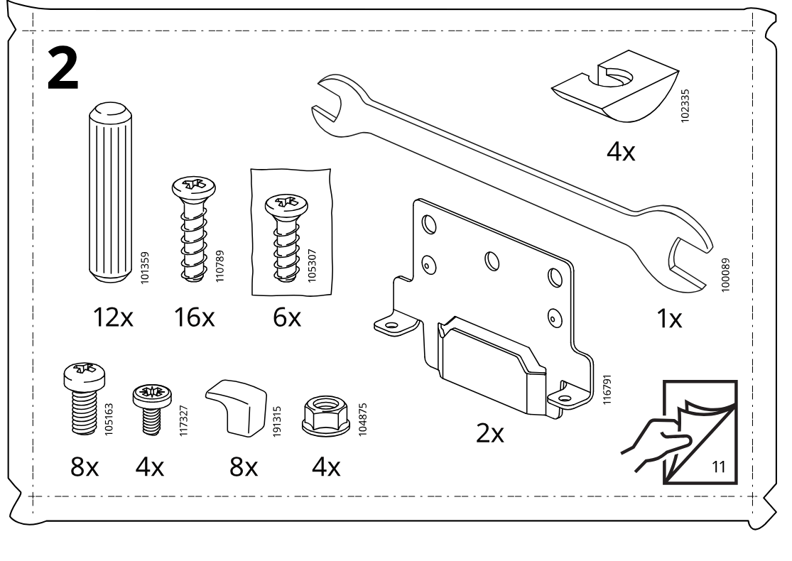
    Illustration for assembly note: Parts-bag reference panel 2 showing included hardware, fittings, wrench, bracket, and quantities for step set 2.
  4. Step 1

    The panel and long rail are laid on a soft surface, and four cam screws (118331) are turned into the rail with a screwdriver.
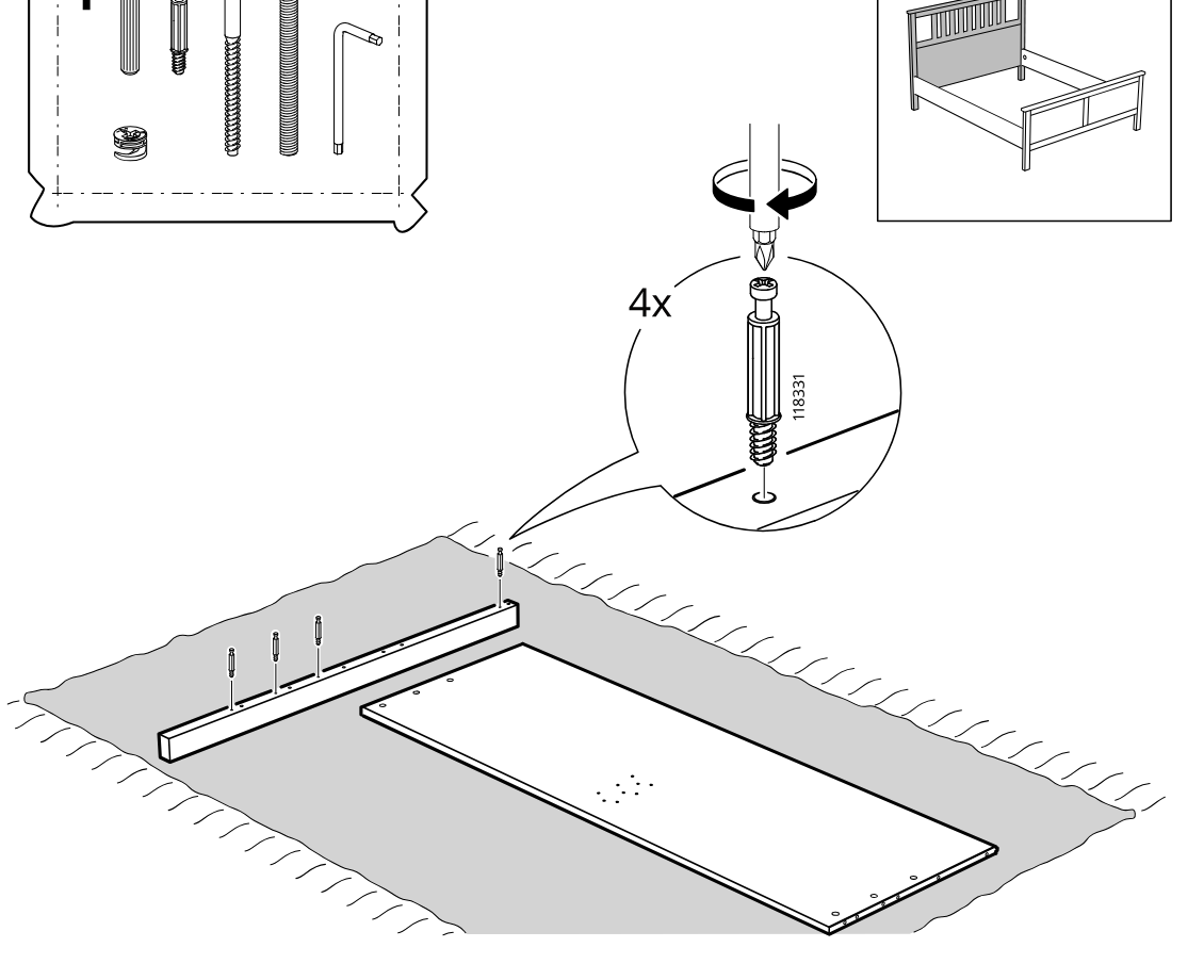
    Diagram for step 1: The panel and long rail are laid on a soft surface, and four cam screws (118331) are turned into the rail with a screwdriver.
  5. Step 2

    Insert four 101352 wooden dowels into the rail and align the panel edge orientation as shown.
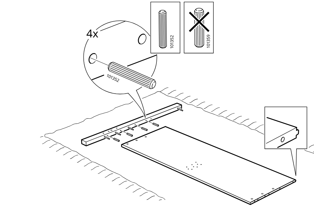
    Diagram for step 2: Insert four 101352 wooden dowels into the rail and align the panel edge orientation as shown.
  6. Step 3

    Place three cam locks into the panel holes and turn them with a screwdriver to lock the rail connection.
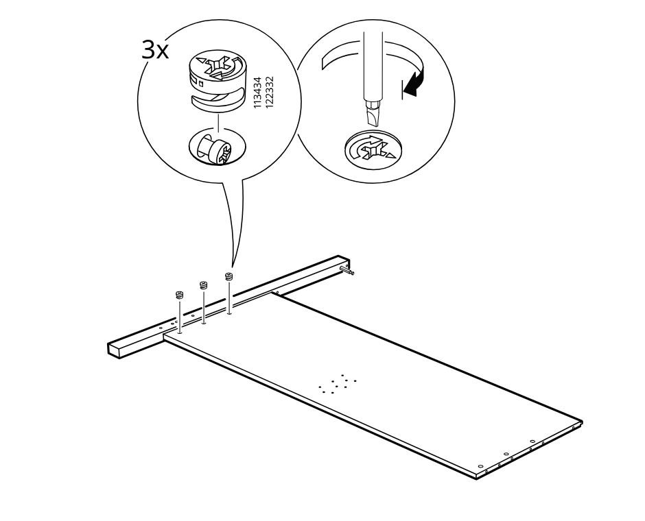
    Diagram for step 3: Place three cam locks into the panel holes and turn them with a screwdriver to lock the rail connection.
  7. Step 4

    Two 101352 dowels are inserted into the rail and panel assembly, with a callout indicating to use 101352 and not 101359.
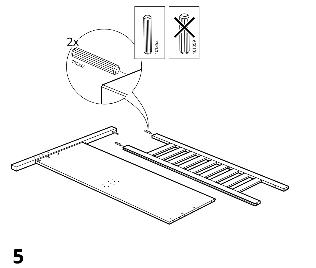
    Diagram for step 4: Two 101352 dowels are inserted into the rail and panel assembly, with a callout indicating to use 101352 and not 101359.
  8. Step 5

    The short slatted section is slid inward along the rails to align and lock into the panel, with a zoom inset showing the joint detail.
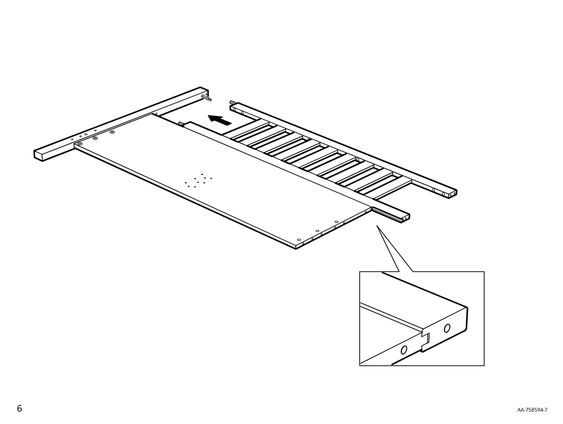
    Diagram for step 5: The short slatted section is slid inward along the rails to align and lock into the panel, with a zoom inset showing the joint detail.
  9. Step 6

    Insert one cam lock fitting into the predrilled hole and turn it with a screwdriver to lock it in place.
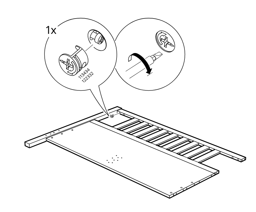
    Diagram for step 6: Insert one cam lock fitting into the predrilled hole and turn it with a screwdriver to lock it in place.
  10. Step 7

    Position the long rail and screw in four threaded fasteners into the marked holes using a screwdriver.
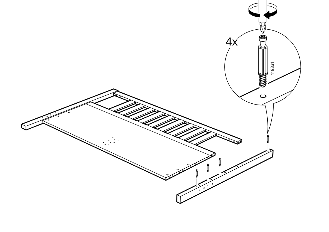
    Diagram for step 7: Position the long rail and screw in four threaded fasteners into the marked holes using a screwdriver.
  11. Step 8

    Six dowels 101352 are inserted into the specified holes, with a callout indicating not to use dowel 101359.
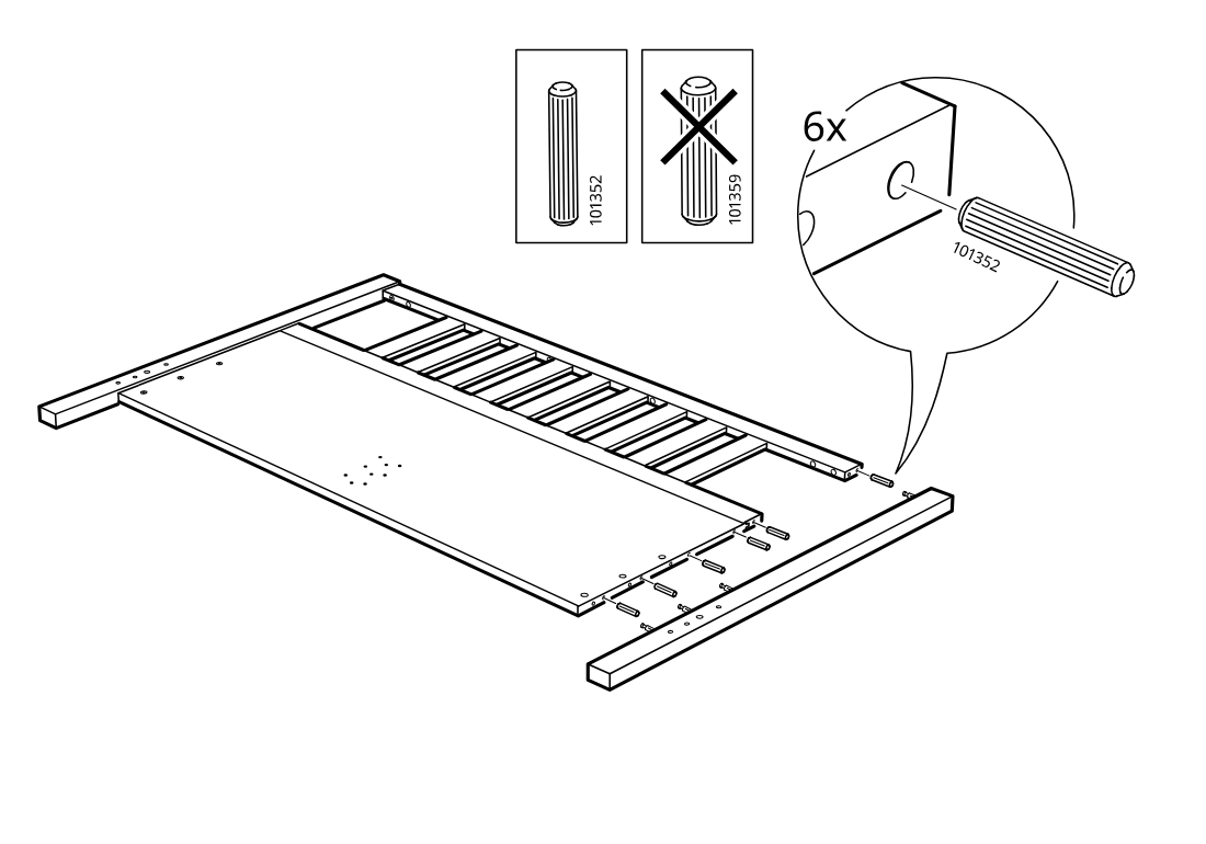
    Diagram for step 8: Six dowels 101352 are inserted into the specified holes, with a callout indicating not to use dowel 101359.
  12. Step 9

    One cam lock assembly (113434/122332) is inserted and turned to lock, with side caution diagrams showing correct and incorrect cam orientation.
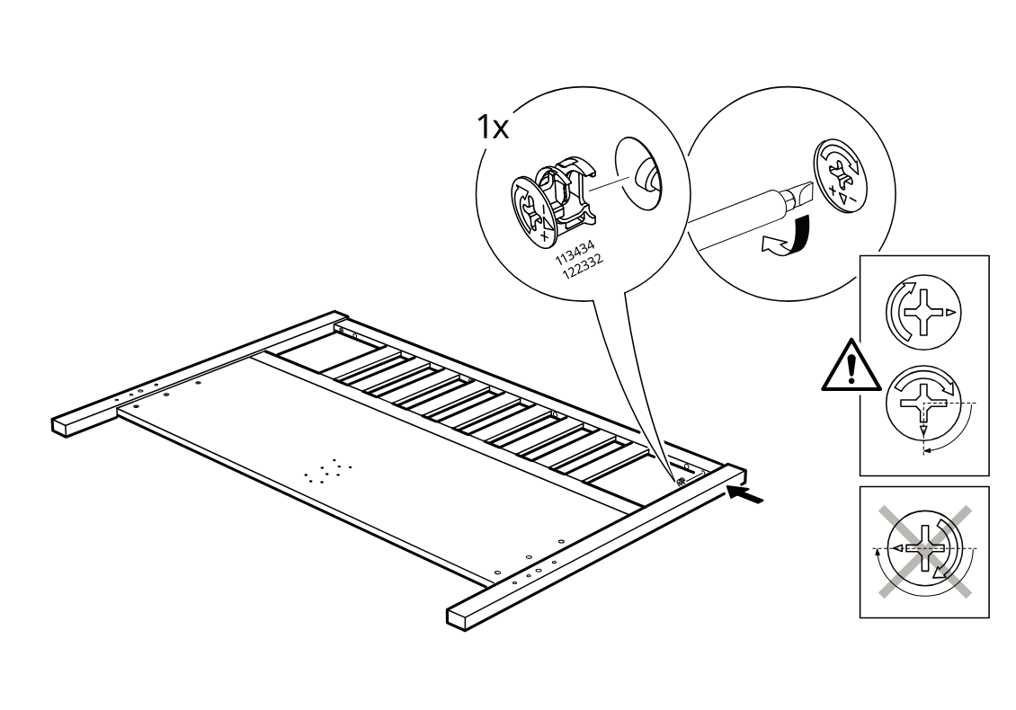
    Diagram for step 9: One cam lock assembly (113434/122332) is inserted and turned to lock, with side caution diagrams showing correct and incorrect cam orientation.
  13. Step 10

    The panel frame is positioned and three cam locks are inserted and turned with a screwdriver to secure the side rail, with a close-up showing the correct cam orientation.
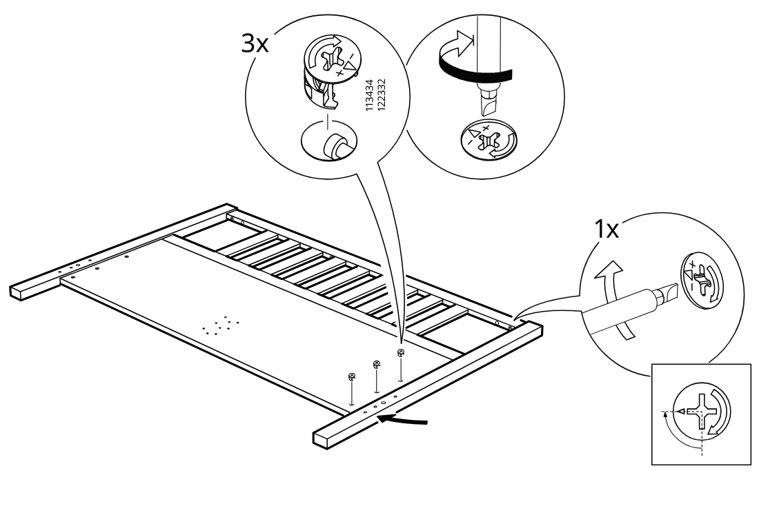
    Diagram for step 10: The panel frame is positioned and three cam locks are inserted and turned with a screwdriver to secure the side rail, with a close-up showing the correct cam orientation.
  14. Step 11

    Six wooden dowels 101352 are inserted into the long rail, while a comparison box indicates not to use dowel 101359.
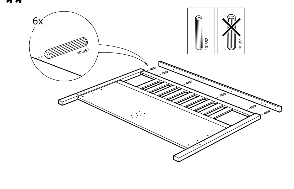
    Diagram for step 11: Six wooden dowels 101352 are inserted into the long rail, while a comparison box indicates not to use dowel 101359.
  15. Step 12

    The panel/frame assembly is fastened with four screws (100087) tightened using the hex key (100092), as shown in the zoomed inset.
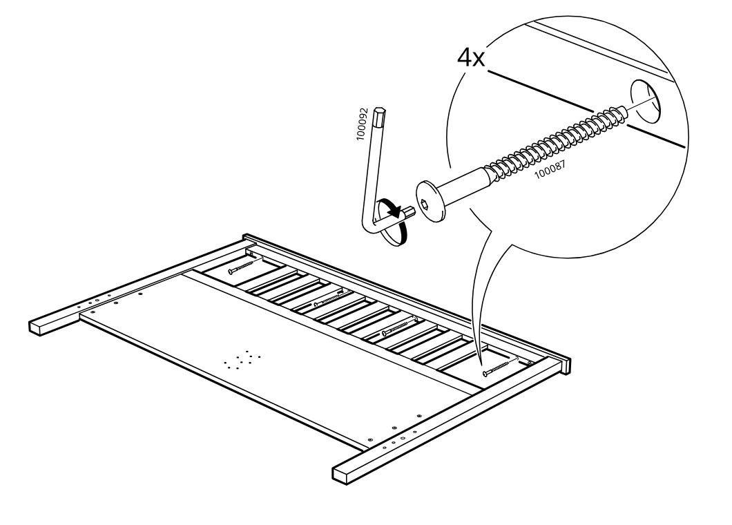
    Diagram for step 12: The panel/frame assembly is fastened with four screws (100087) tightened using the hex key (100092), as shown in the zoomed inset.
  16. Step 13

    Two threaded studs (111451) are screwed into the indicated inserts on the frame, with the zoomed inset showing the turning direction.
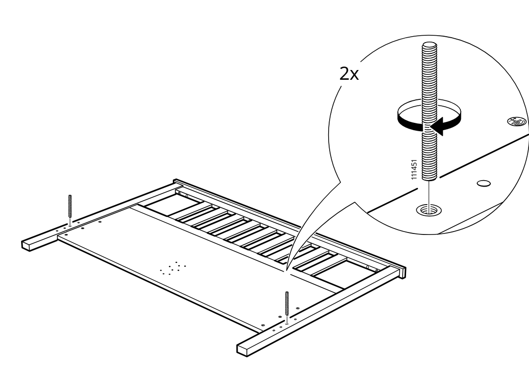
    Diagram for step 13: Two threaded studs (111451) are screwed into the indicated inserts on the frame, with the zoomed inset showing the turning direction.
  17. Step 14

    Two threaded rods (111451) are screwed into the predrilled holes at the ends of the long side frame panel.
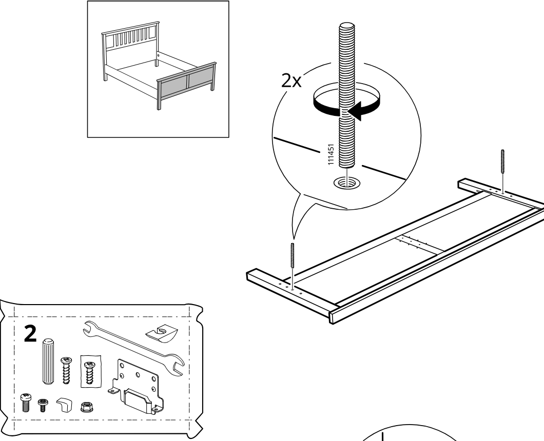
    Diagram for step 14: Two threaded rods (111451) are screwed into the predrilled holes at the ends of the long side frame panel.
  18. Step 15

    Three dowels (101359) are inserted into the headboard side while aligning the mating side panel in the correct orientation.
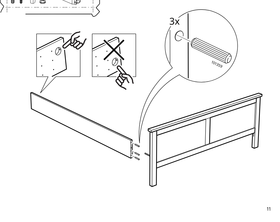
    Diagram for step 15: Three dowels (101359) are inserted into the headboard side while aligning the mating side panel in the correct orientation.
  19. Step 16

    Attach the side panel to the frame with one bolt and nut, then tighten it using the wrench as shown in the zoom sequence.
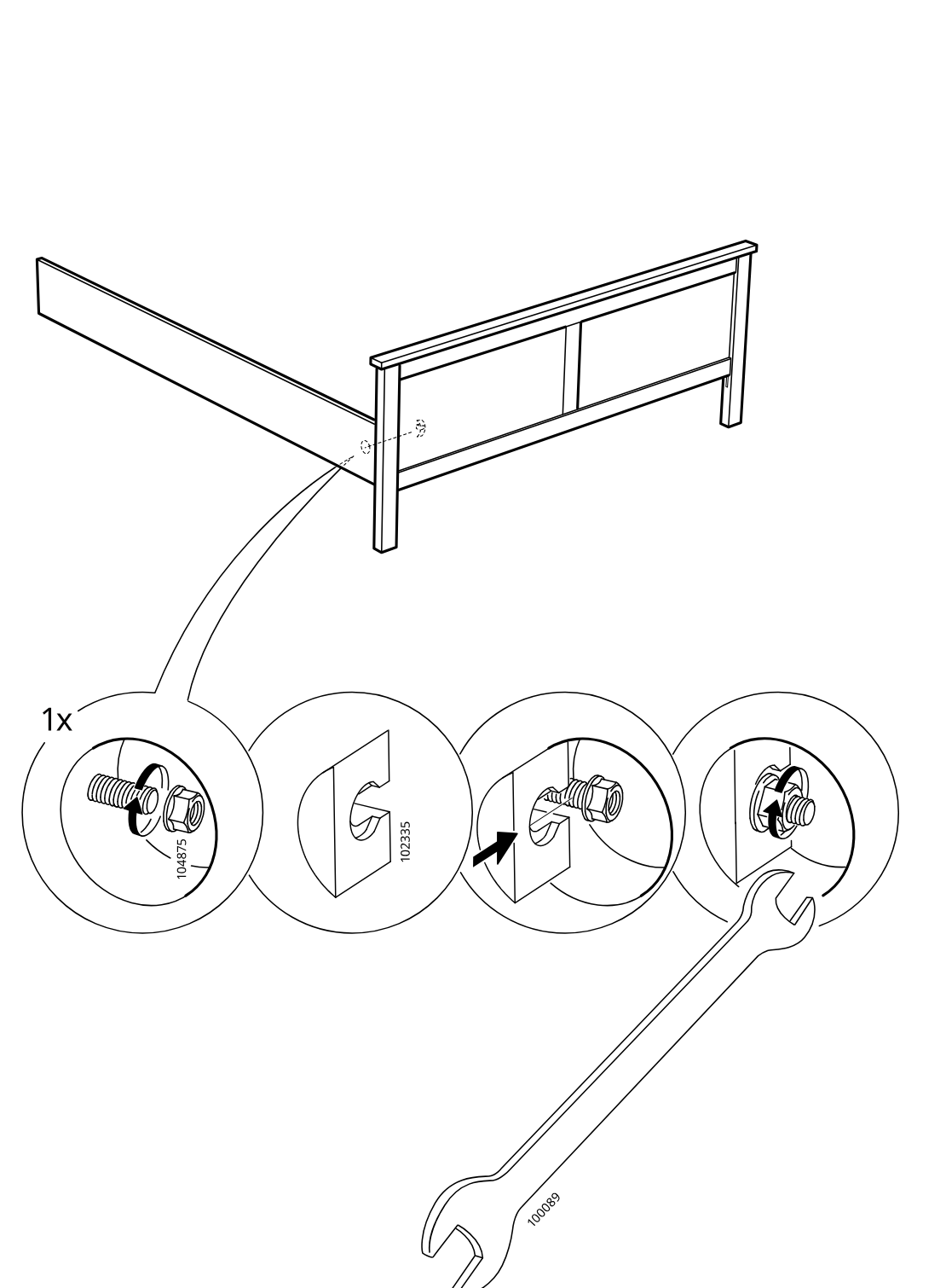
    Diagram for step 16: Attach the side panel to the frame with one bolt and nut, then tighten it using the wrench as shown in the zoom sequence.
  20. Step 17

    Insert three 101359 wooden dowels into the side panel and orient the panel correctly before positioning it onto the bed frame.
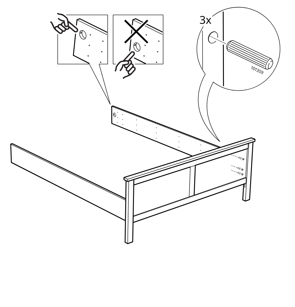
    Diagram for step 17: Insert three 101359 wooden dowels into the side panel and orient the panel correctly before positioning it onto the bed frame.
  21. Step 18

    The side rail is secured to the headboard with one bolt-and-nut fastener, then tightened using the included wrench as shown in the zoom sequence.
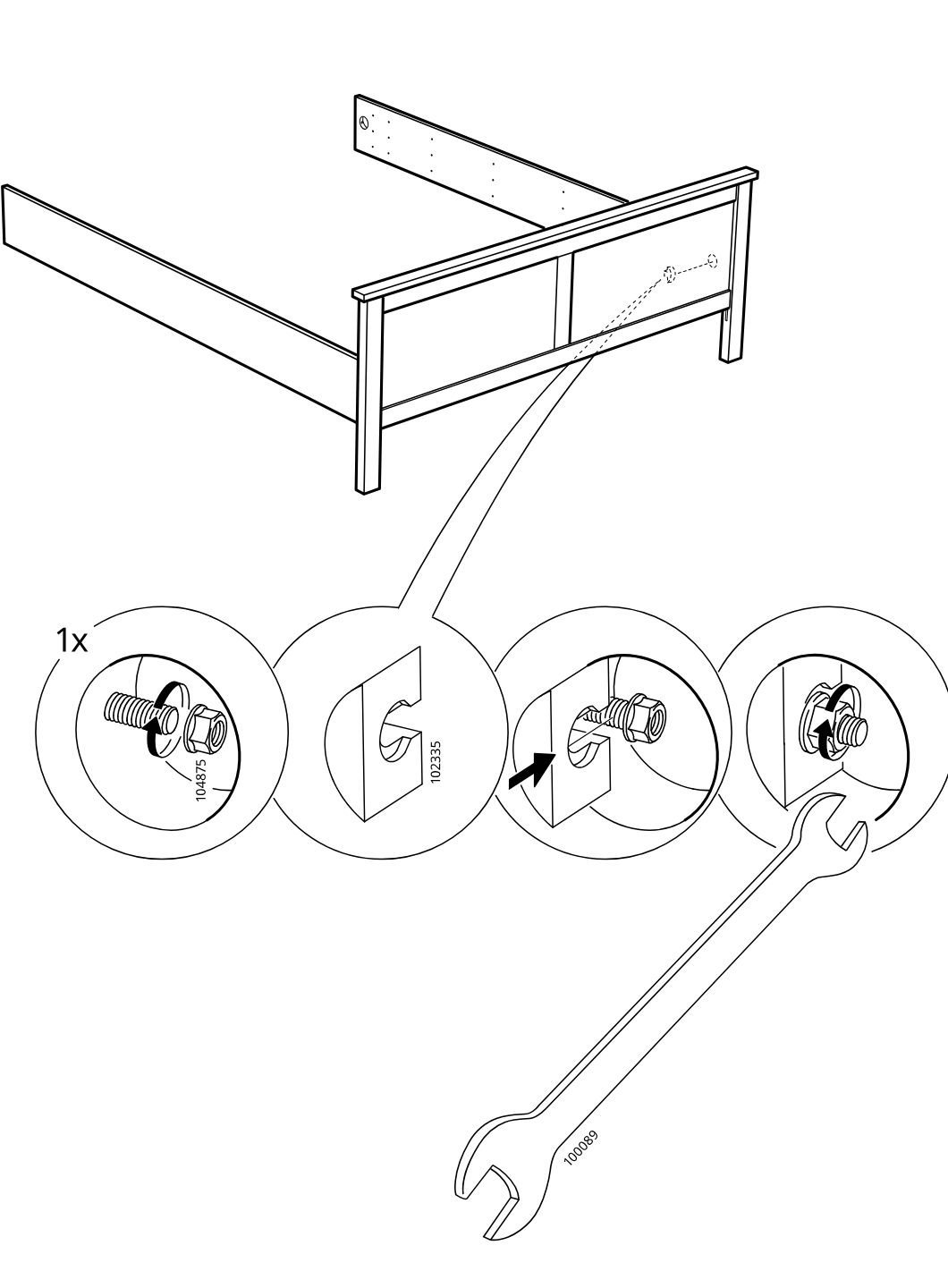
    Diagram for step 18: The side rail is secured to the headboard with one bolt-and-nut fastener, then tightened using the included wrench as shown in the zoom sequence.
  22. Step 19

    Two people align the long side panel between the bed frame ends and insert six wooden dowels into the side joints before fastening.
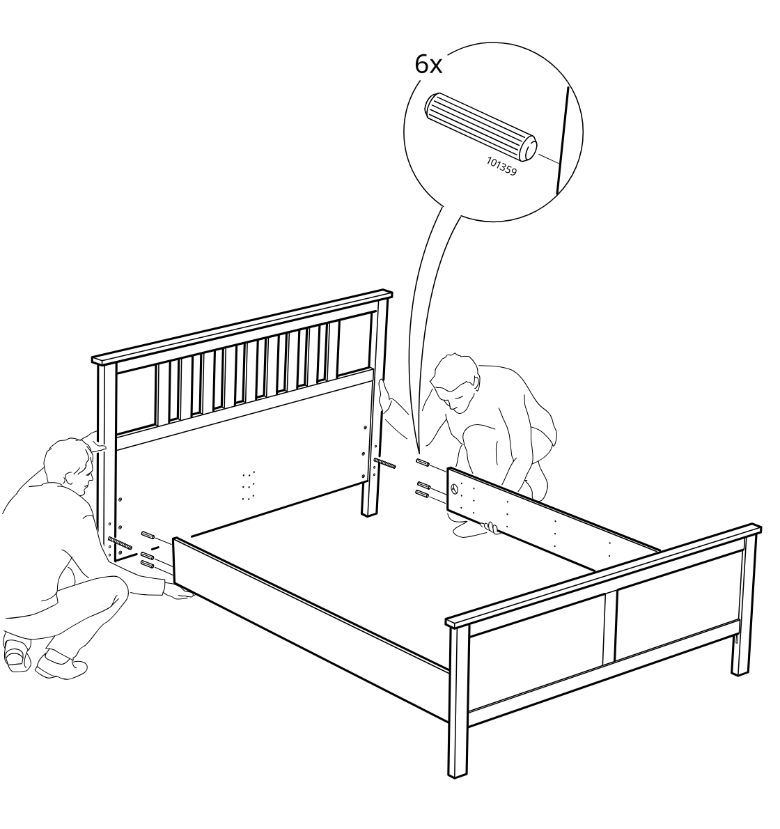
    Diagram for step 19: Two people align the long side panel between the bed frame ends and insert six wooden dowels into the side joints before fastening.
  23. Step 20

    The side rails are secured to the headboard and footboard with two bolt-and-nut fasteners, using the included wrench while aligning the fittings as shown in the zoom callouts.
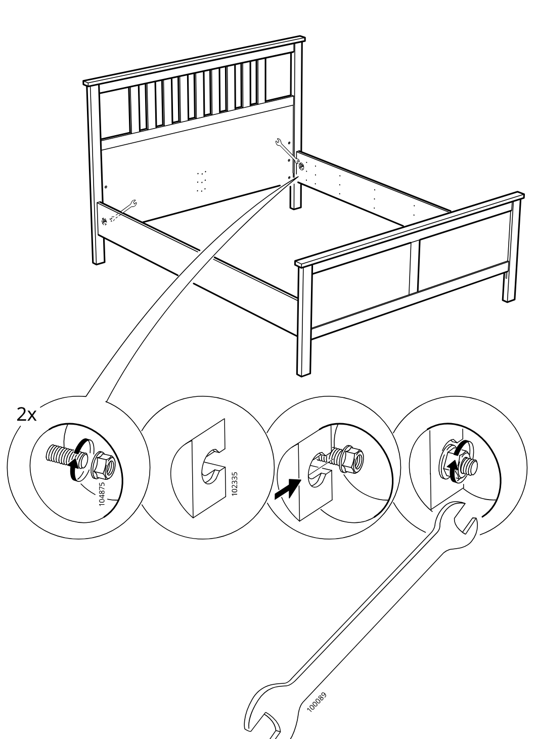
    Diagram for step 20: The side rails are secured to the headboard and footboard with two bolt-and-nut fasteners, using the included wrench while aligning the fittings as shown in the zoom callouts.
  24. Before you begin

    A standalone circled-i panel shows three close-up orientation/position examples for aligning and placing the side rail components on the bed frame.
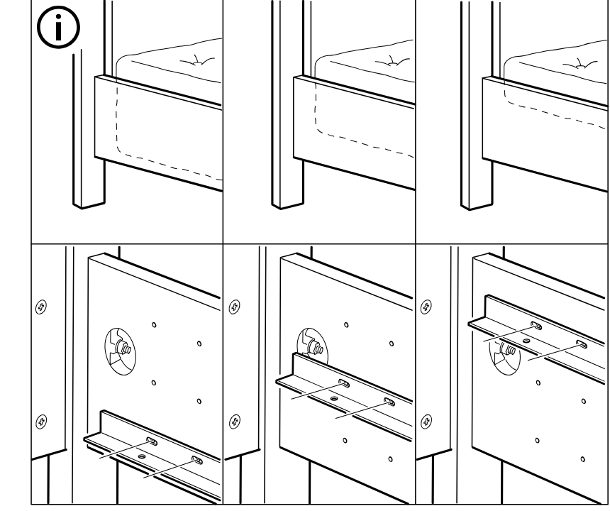
    Illustration for assembly note: A standalone circled-i panel shows three close-up orientation/position examples for aligning and placing the side rail components on the bed frame.
  25. Step 21

    The side rails are fixed to the headboard and footboard with 16 screws (110789) using a screwdriver, while the callout indicates the correct screw type and excludes two incorrect screws.
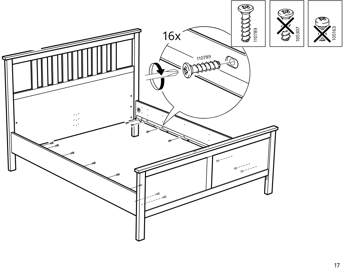
    Diagram for step 21: The side rails are fixed to the headboard and footboard with 16 screws (110789) using a screwdriver, while the callout indicates the correct screw type and excludes two incorrect screws.
  26. Before you begin

    Circled information panel shows three orientation/placement views for positioning and fastening the bracket on the bed side panel.
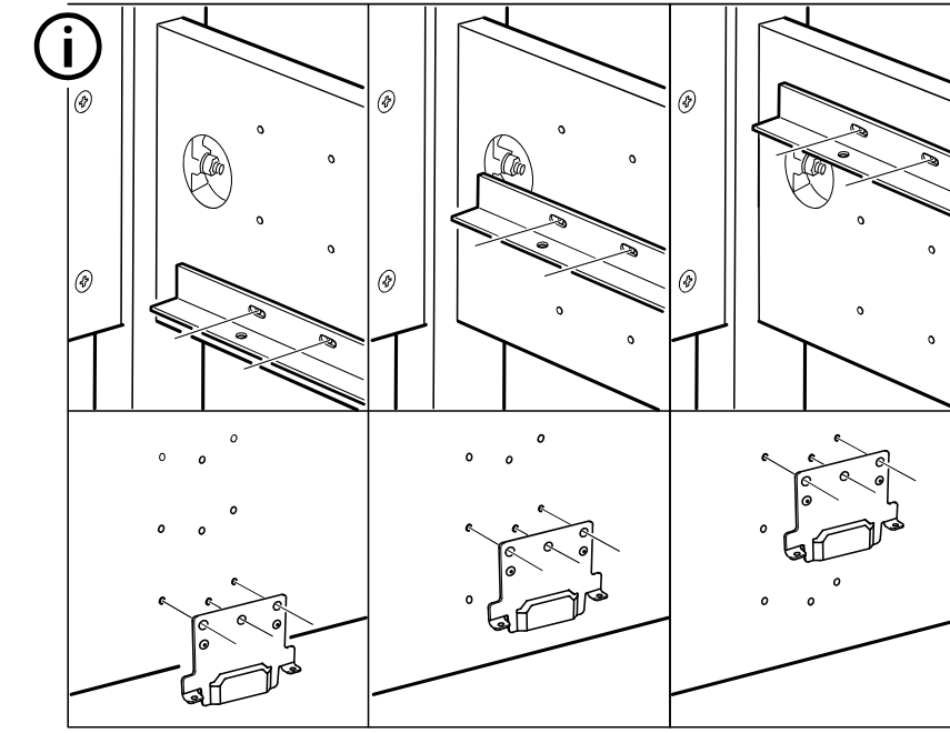
    Illustration for assembly note: Circled information panel shows three orientation/placement views for positioning and fastening the bracket on the bed side panel.
  27. Step 22

    Attach two brackets to the bed frame using screws, as shown in the enlarged callout, with mirrored installation points on the frame.
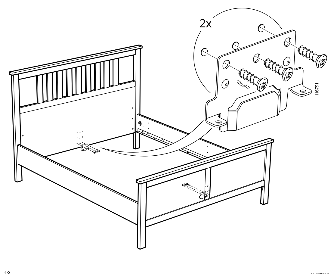
    Diagram for step 22: Attach two brackets to the bed frame using screws, as shown in the enlarged callout, with mirrored installation points on the frame.
  28. Step 23

    Attach the metal clip part 124402 onto the long side rail and slide it into position near the rail end.
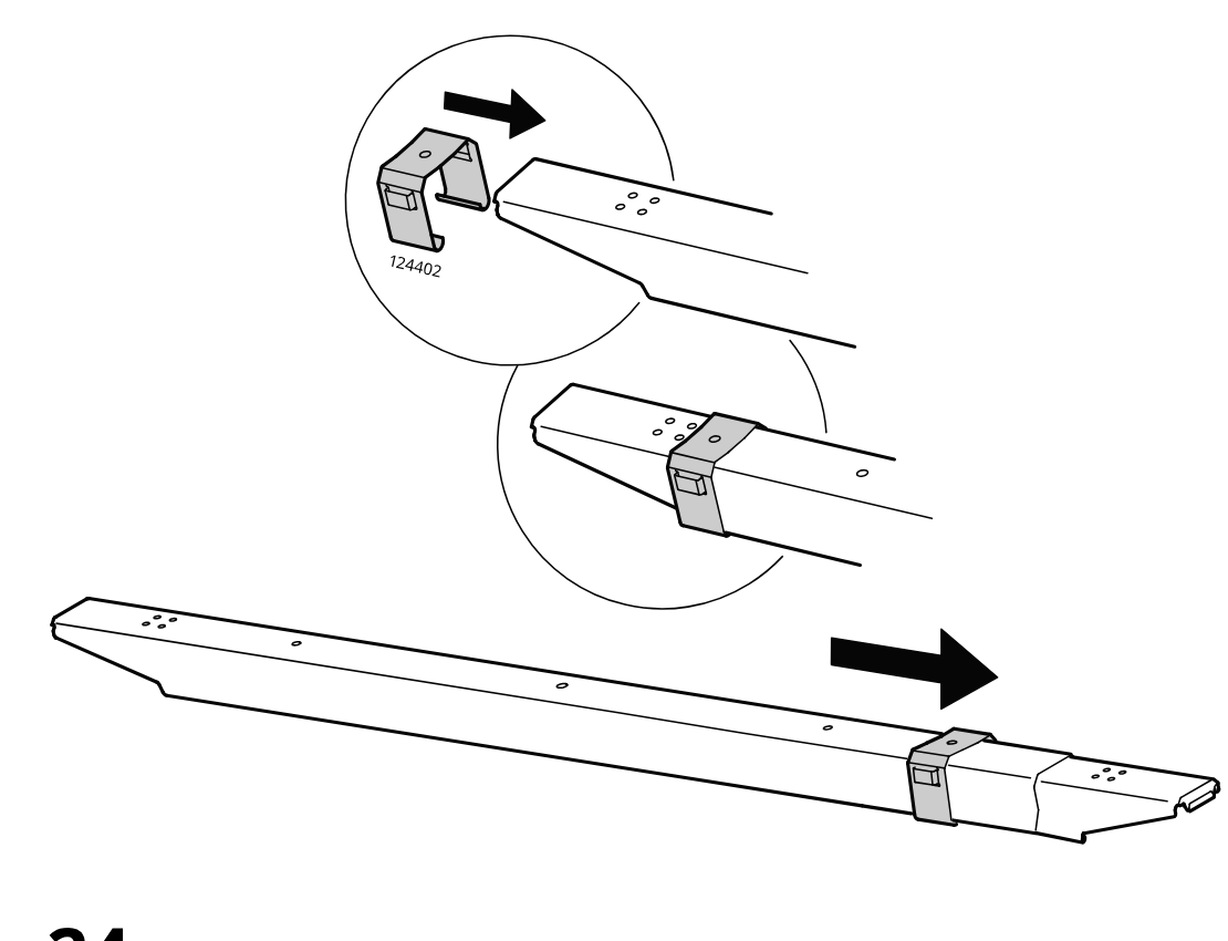
    Diagram for step 23: Attach the metal clip part 124402 onto the long side rail and slide it into position near the rail end.
  29. Step 24

    Place the prepared side rail into the bed frame, lowering one end into the rear bracket and then aligning and lowering the front end into its slot.
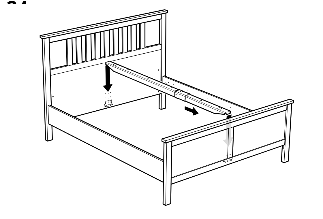
    Diagram for step 24: Place the prepared side rail into the bed frame, lowering one end into the rear bracket and then aligning and lowering the front end into its slot.
  30. Step 25

    Two rail parts are positioned between the bed frames and secured with one screw at the shown point using a screwdriver, as detailed in the zoom callout.
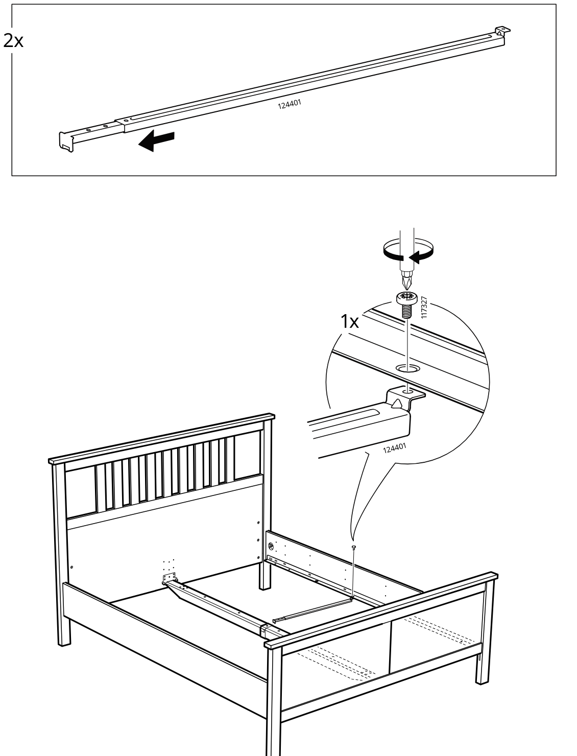
    Diagram for step 25: Two rail parts are positioned between the bed frames and secured with one screw at the shown point using a screwdriver, as detailed in the zoom callout.
  31. Step 26

    Insert one clip piece (124401) onto the rail connection and slide the center rail assembly into position between the bed sides as shown.
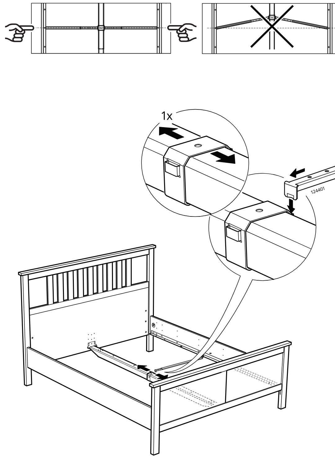
    Diagram for step 26: Insert one clip piece (124401) onto the rail connection and slide the center rail assembly into position between the bed sides as shown.
  32. Step 27

    The side rail is hooked into the corner bracket and one screw is inserted to secure the rail connection.
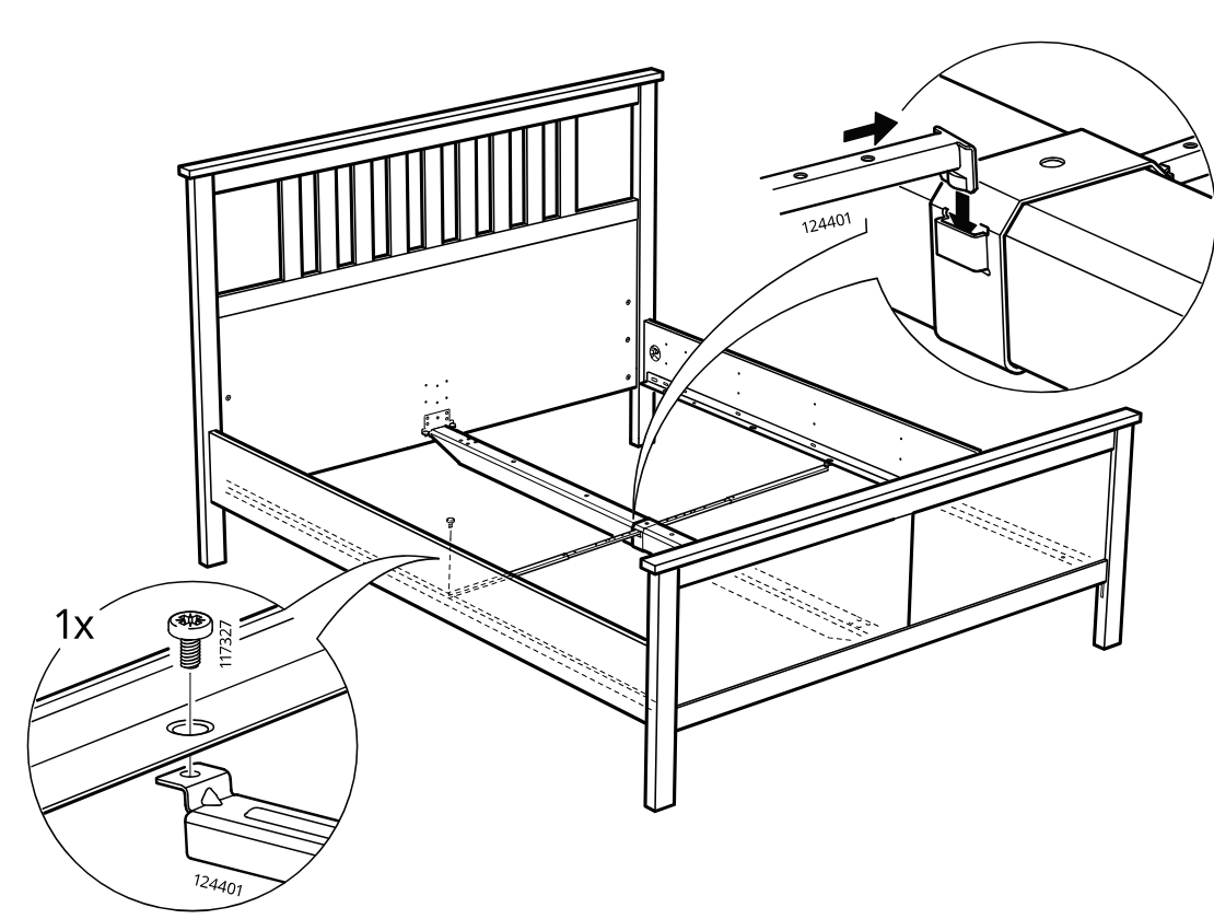
    Diagram for step 27: The side rail is hooked into the corner bracket and one screw is inserted to secure the rail connection.
  33. Step 28

    Two screws are fastened into the rail from above to further secure the bed frame assembly.
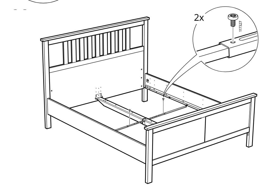
    Diagram for step 28: Two screws are fastened into the rail from above to further secure the bed frame assembly.
  34. Before you begin

    Information panel shows removing or releasing the slats using part 191315 and screw 105163 at 8 positions.
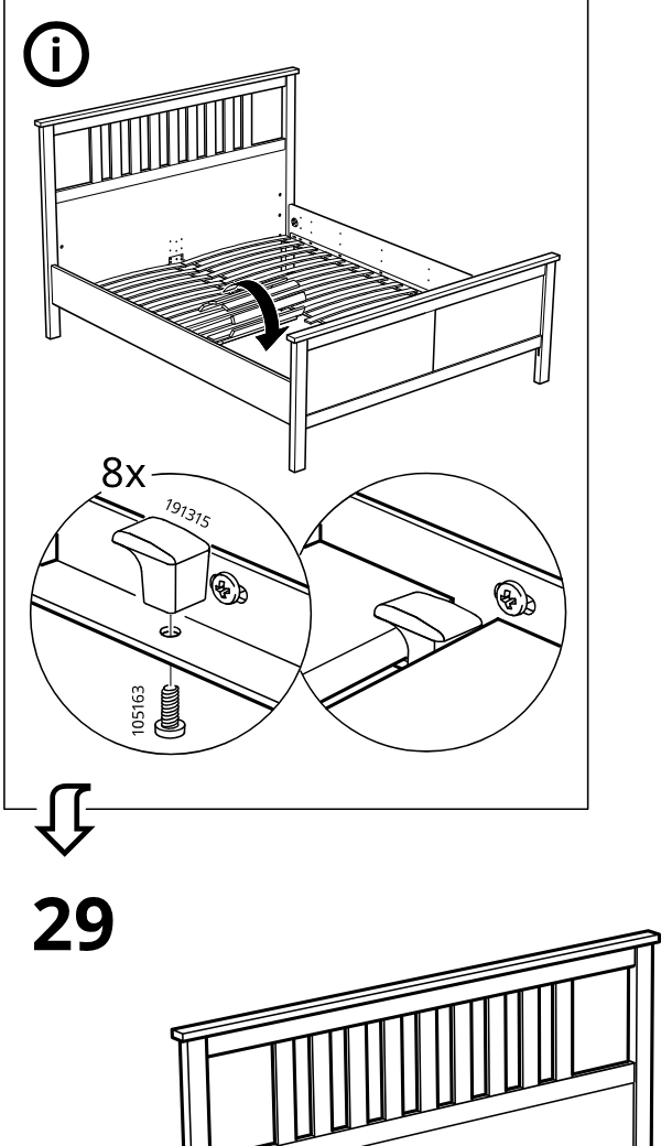
    Illustration for assembly note: Information panel shows removing or releasing the slats using part 191315 and screw 105163 at 8 positions.
  35. Step 29

    The bed frame is assembled by fastening side rails and center support connections to the headboard and footboard with screws at the indicated points.
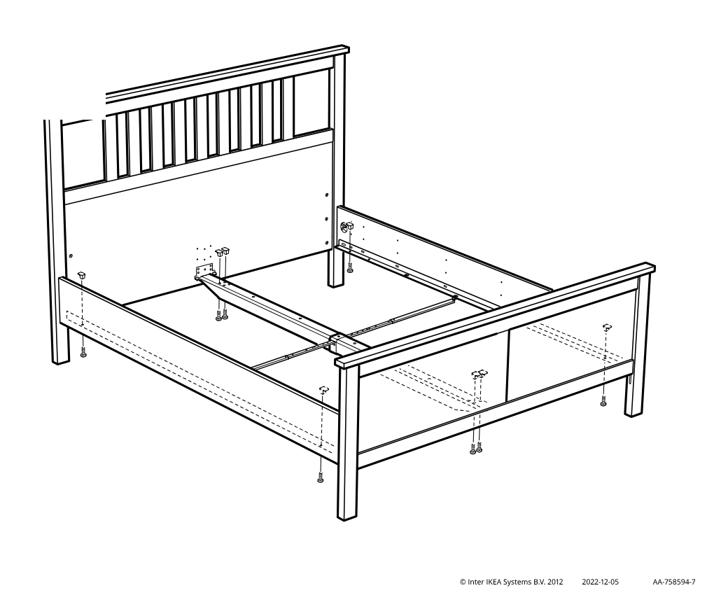
    Diagram for step 29: The bed frame is assembled by fastening side rails and center support connections to the headboard and footboard with screws at the indicated points.

Video guide