How to assemble IKEA HEMNES daybed frame with 3 drawers

HEMNES daybed frame with 3 drawers, white

This guide covers the white IKEA HEMNES daybed frame with 3 drawers, article 303.493.29. Follow the daybed assembly diagrams and video for this model.

View on IKEA
HEMNES daybed frame with 3 drawers

Interactive assembly guide

Step-by-Step Instructions

1 different parts, 1 boxes total — click on a package to see step-by-step assembly instructions

HEMNES Daybed frame with 3 drawers

303.493.29

x1

20 ¾ "

Width

2 ¼ "

Height

80 ½ "

Length

58 lb 11 oz

Weight

Start Assembly

Written guide

Step-by-step instructions with diagrams

Follow the numbered assembly steps below, or open the interactive guide above to track progress and zoom into each diagram. This guide includes 42 illustrated steps.

HEMNES Daybed frame with 3 drawers

  1. Before you begin

    Preparation and safety panels show required tools, recommend two-person assembly, warn against assembling on hard surfaces, and advise reading instructions or contacting IKEA support if unsure.
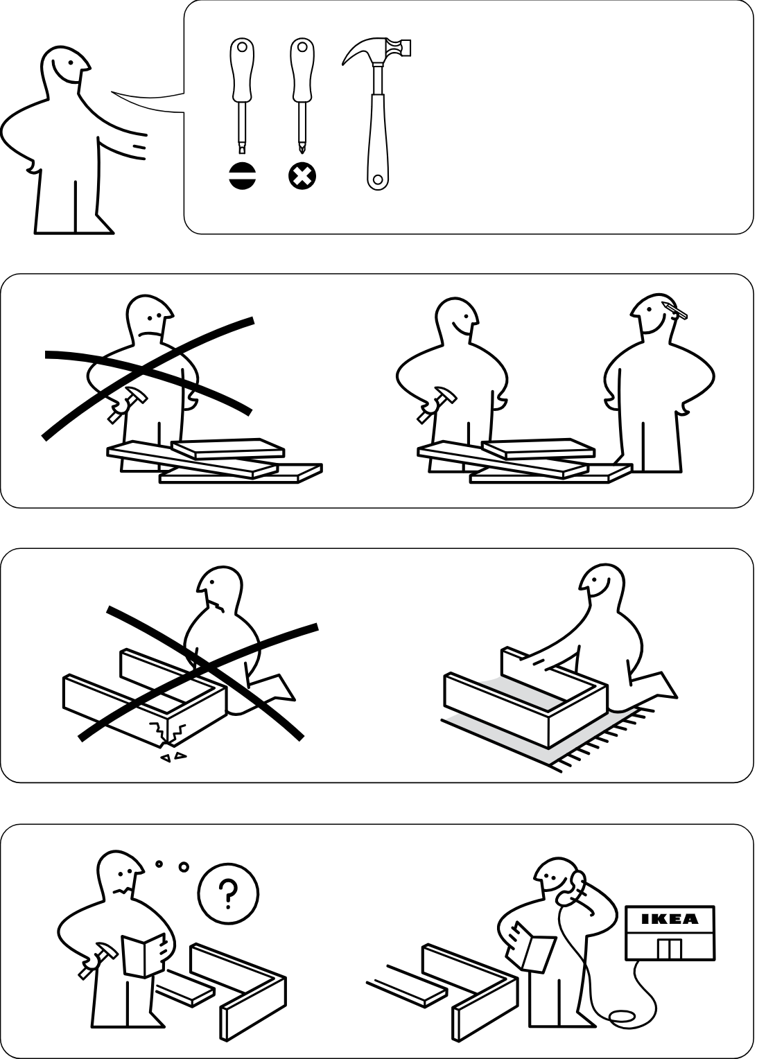
    Illustration for assembly note: Preparation and safety panels show required tools, recommend two-person assembly, warn against assembling on hard surfaces, and advise reading instructions or contacting IKEA support if unsure.
  2. Before you begin

    Parts-bag reference panel 1 showing required hardware and fittings with quantities for bag 6.
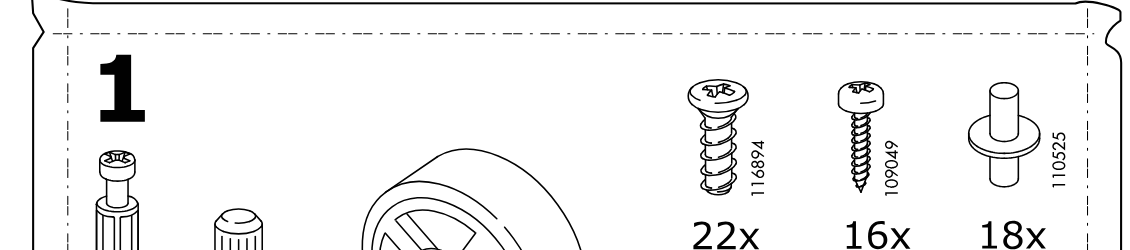
    Illustration for assembly note: Parts-bag reference panel 1 showing required hardware and fittings with quantities for bag 6.
  3. Before you begin

    Parts-bag reference panel 2 showing required hardware, tool, and fittings with quantities for bag 19.
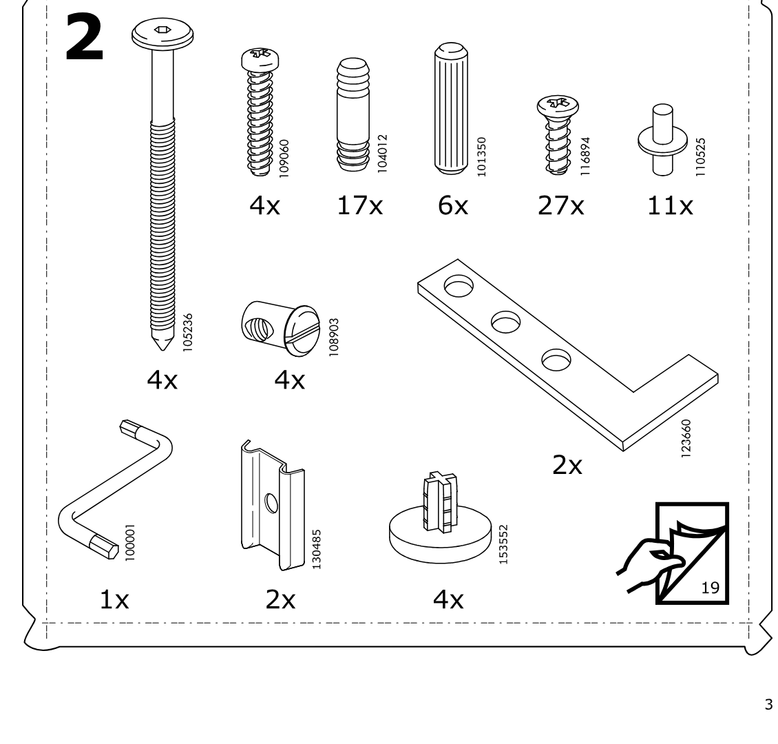
    Illustration for assembly note: Parts-bag reference panel 2 showing required hardware, tool, and fittings with quantities for bag 19.
  4. Before you begin

    Hardware bag 3 shows four fastener types with part numbers and quantities, plus a note that one item continues on page 29.
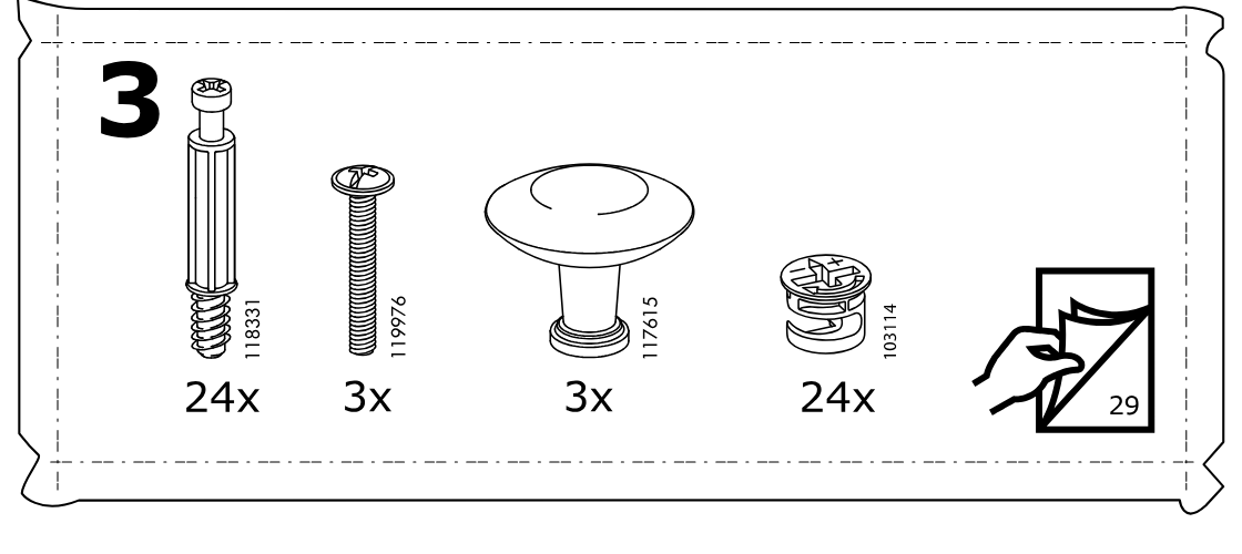
    Illustration for assembly note: Hardware bag 3 shows four fastener types with part numbers and quantities, plus a note that one item continues on page 29.
  5. Before you begin

    Hardware bag 4 shows screw part 100347 with quantity 36x.
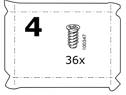
    Illustration for assembly note: Hardware bag 4 shows screw part 100347 with quantity 36x.
  6. Before you begin

    Hardware bag section shows drawer slide part 139505 with quantity 3x.
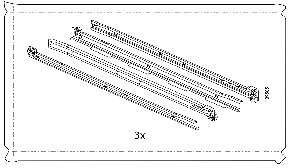
    Illustration for assembly note: Hardware bag section shows drawer slide part 139505 with quantity 3x.
  7. Step 1

    Attach eight caster brackets to the four long rails with screws, using the shown orientation and end-hole reference.
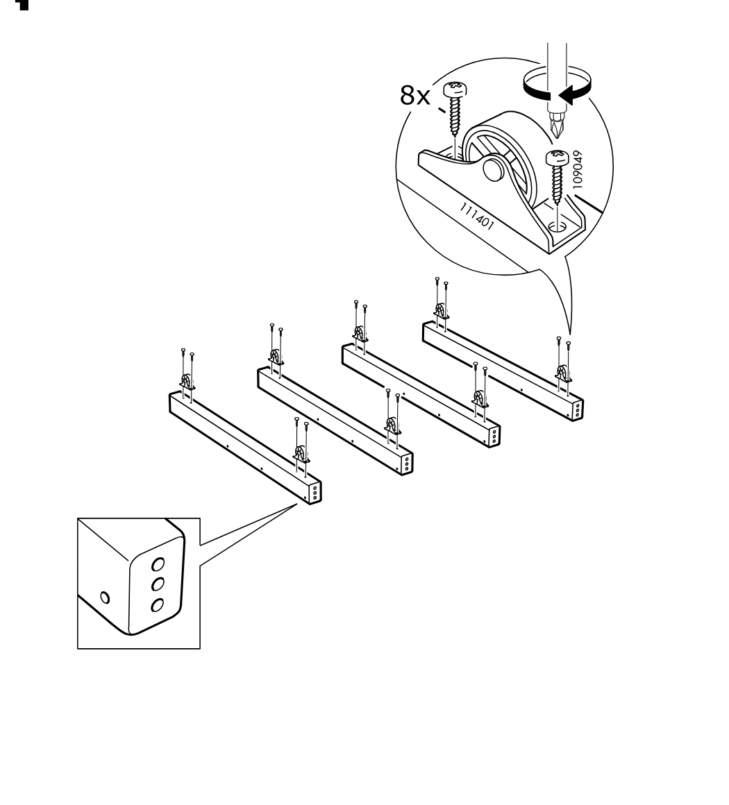
    Diagram for step 1: Attach eight caster brackets to the four long rails with screws, using the shown orientation and end-hole reference.
  8. Step 2

    The installer mounts CR drawer runners onto four frame rails using nine screws (100347), with a close-up showing screw location, screwdriver direction, and the correct screw type versus an incorrect one.
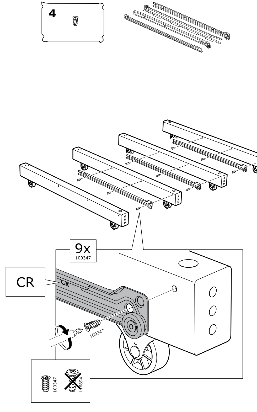
    Diagram for step 2: The installer mounts CR drawer runners onto four frame rails using nine screws (100347), with a close-up showing screw location, screwdriver direction, and the correct screw type versus an incorrect one.
  9. Step 3

    Attach the CL-marked rail components using screw 100347 on all four assemblies, with a total of 9 screws, and use the specified screw type (not 16894).
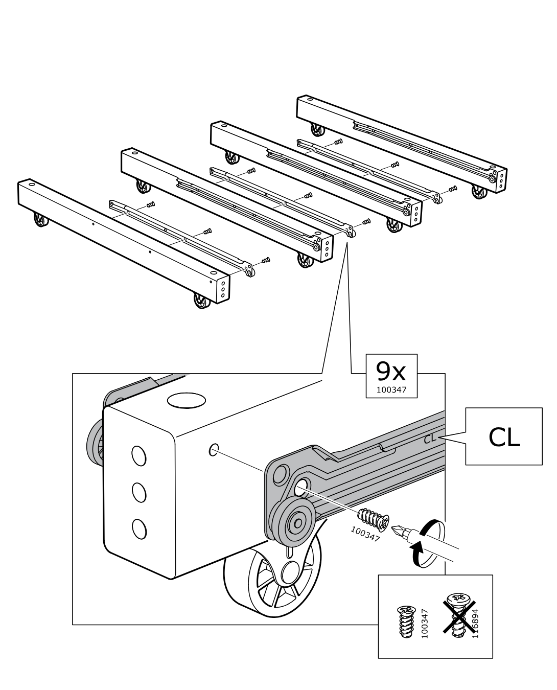
    Diagram for step 3: Attach the CL-marked rail components using screw 100347 on all four assemblies, with a total of 9 screws, and use the specified screw type (not 16894).
  10. Step 4

    Insert eight dowels (101350) into the end holes of the four long frame pieces.
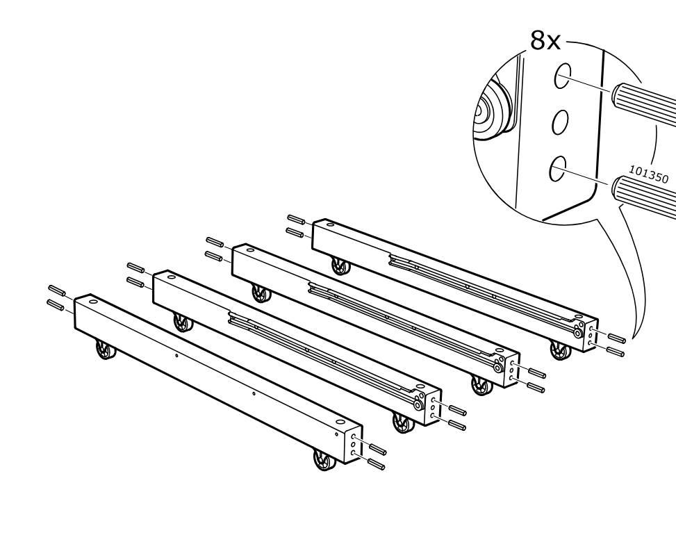
    Diagram for step 4: Insert eight dowels (101350) into the end holes of the four long frame pieces.
  11. Step 5

    Screw two 116894 screws through the rail into the panel while using a screwdriver and ensuring the correct screw type is selected.
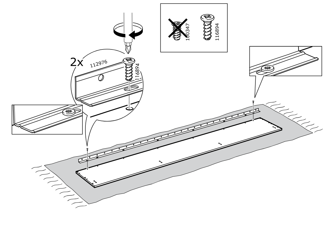
    Diagram for step 5: Screw two 116894 screws through the rail into the panel while using a screwdriver and ensuring the correct screw type is selected.
  12. Step 6

    The rail is positioned on the long panel and six screws (116894) are driven in, with a callout indicating not to use screw 100347 and an inset showing correct screw seating.
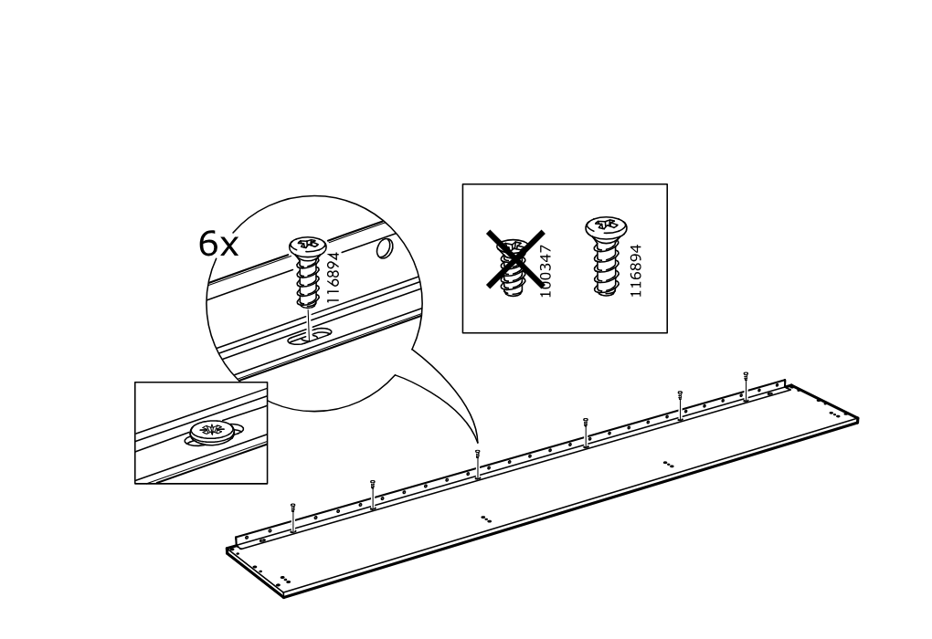
    Diagram for step 6: The rail is positioned on the long panel and six screws (116894) are driven in, with a callout indicating not to use screw 100347 and an inset showing correct screw seating.
  13. Step 7

    Eight cam bolts (118331) are inserted into the panel and tightened with a screwdriver, as shown by the rotation arrow and zoomed detail callout.
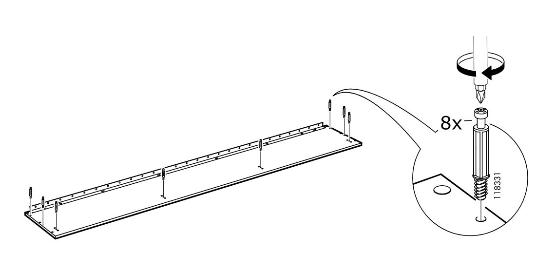
    Diagram for step 7: Eight cam bolts (118331) are inserted into the panel and tightened with a screwdriver, as shown by the rotation arrow and zoomed detail callout.
  14. Step 8

    Four vertical side panels are positioned upright onto the base panel, with close-up callouts showing the top cam fittings and wheel-side orientation.
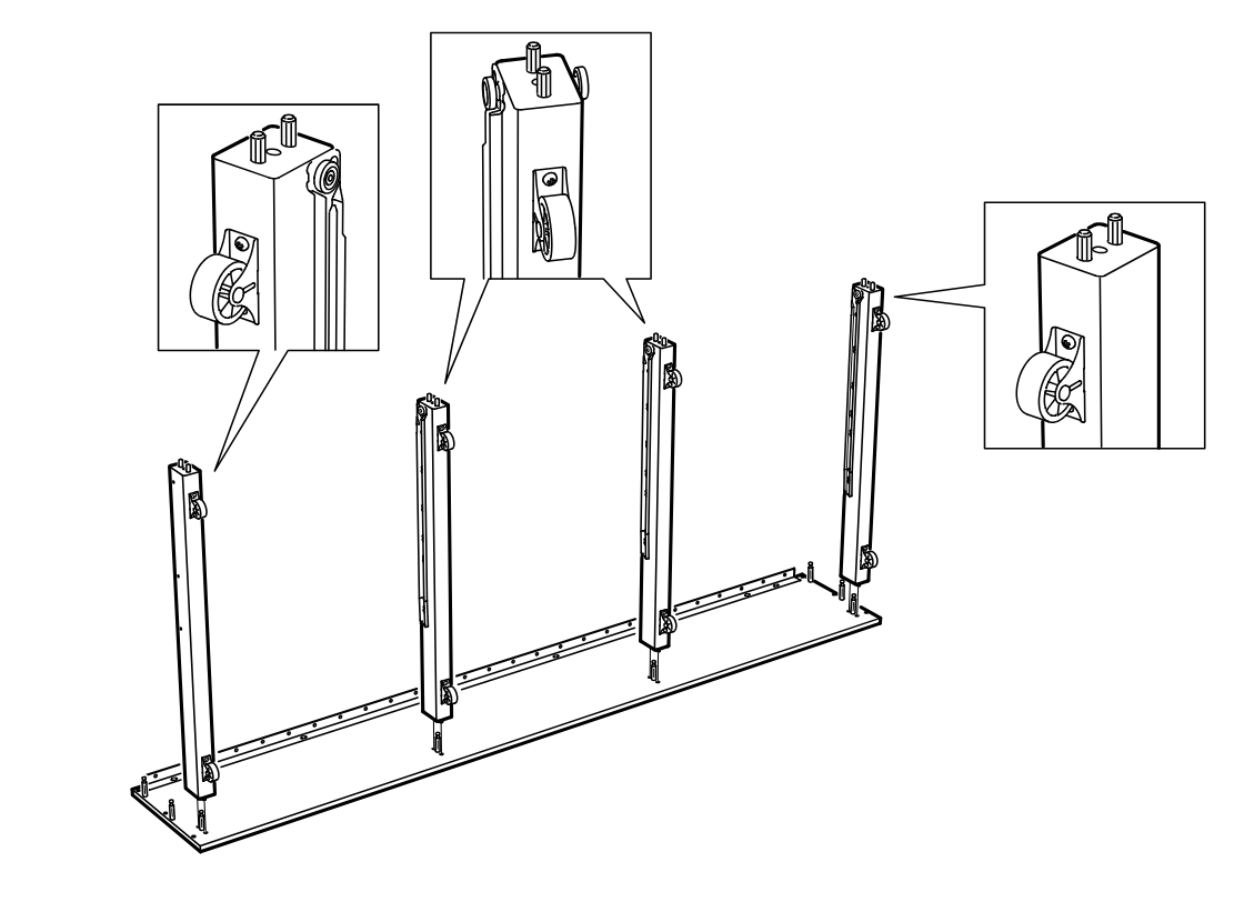
    Diagram for step 8: Four vertical side panels are positioned upright onto the base panel, with close-up callouts showing the top cam fittings and wheel-side orientation.
  15. Step 9

    Four cam locks (10430) are inserted and tightened with a screwdriver at the indicated points to secure the upright panels to the base.
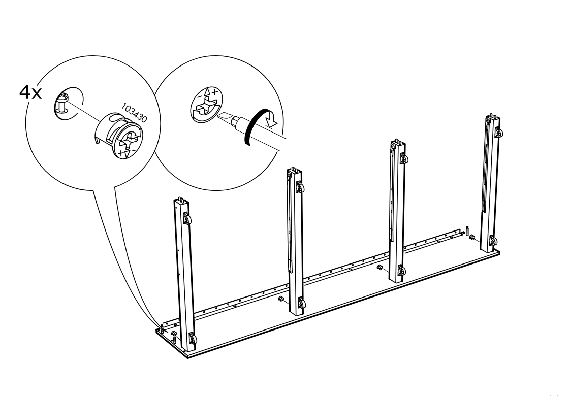
    Diagram for step 9: Four cam locks (10430) are inserted and tightened with a screwdriver at the indicated points to secure the upright panels to the base.
  16. Step 10

    Insert twelve wooden dowels into the predrilled holes of the two rectangular panels as shown in the zoom callout and exploded view.
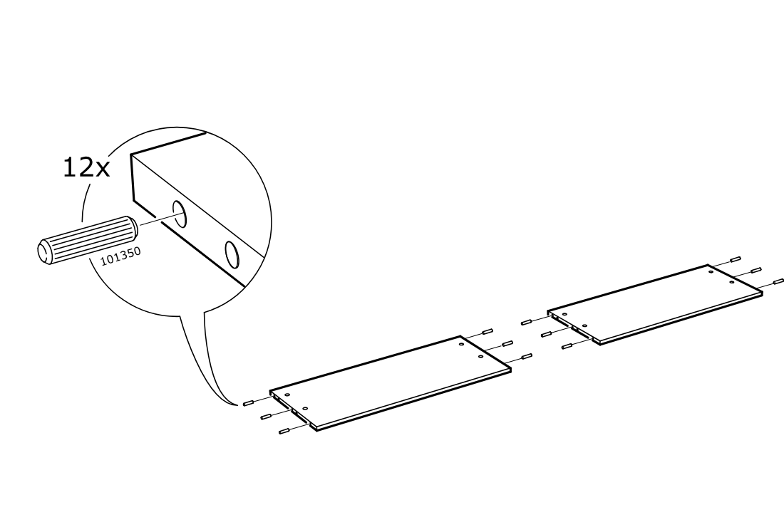
    Diagram for step 10: Insert twelve wooden dowels into the predrilled holes of the two rectangular panels as shown in the zoom callout and exploded view.
  17. Step 11

    Position and attach the two outer side panels and two inner vertical dividers upright onto the long base panel, aligning them with the predrilled hole lines.
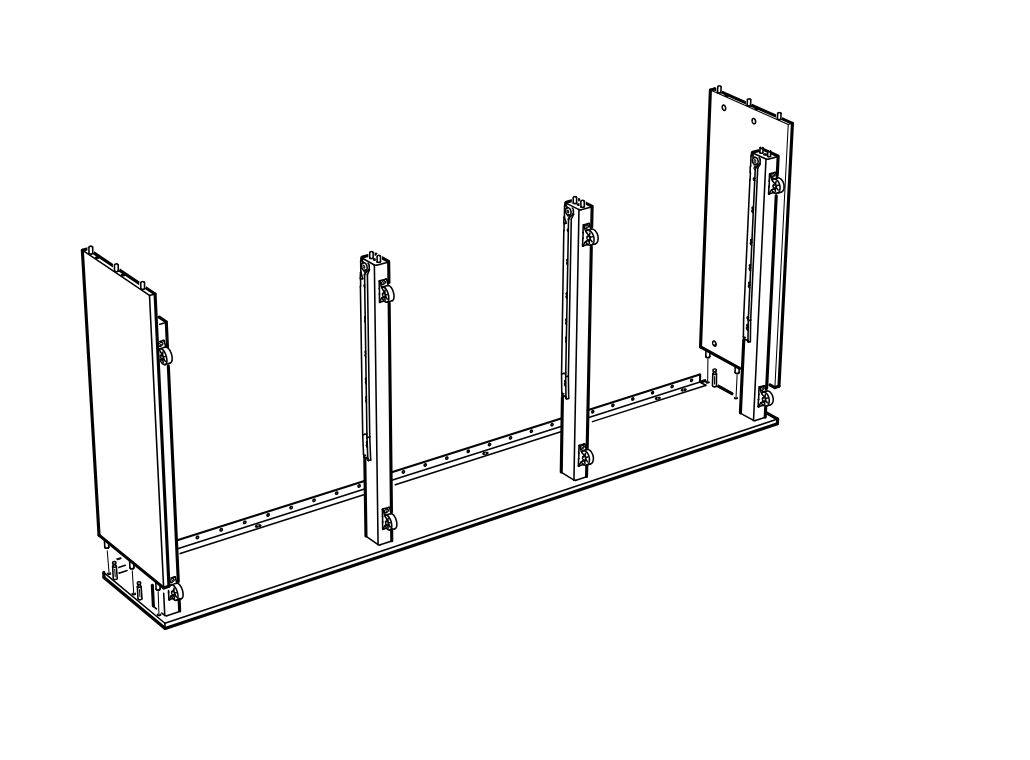
    Diagram for step 11: Position and attach the two outer side panels and two inner vertical dividers upright onto the long base panel, aligning them with the predrilled hole lines.
  18. Step 12

    The cam locks are inserted and turned to secure the upright panels to the long base panel.
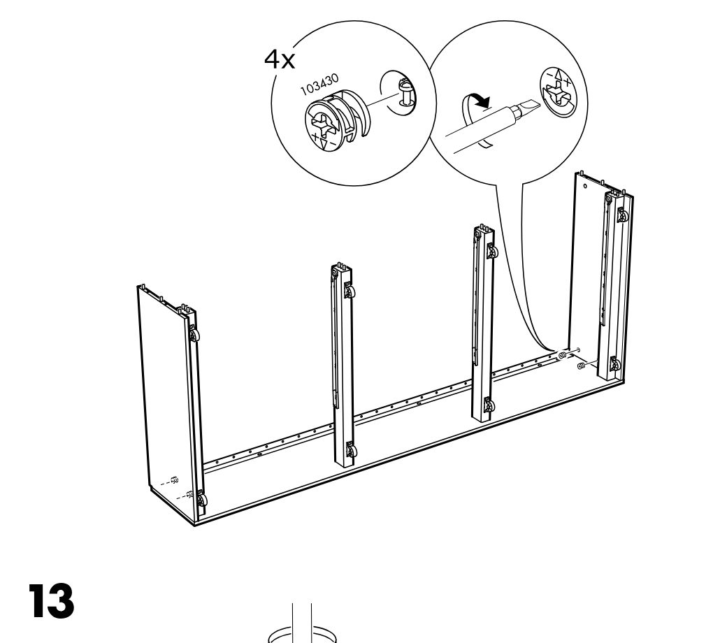
    Diagram for step 12: The cam locks are inserted and turned to secure the upright panels to the long base panel.
  19. Step 13

    Two rail pieces are fixed onto the panel with screws, using the specified screw type while avoiding the crossed-out screw.
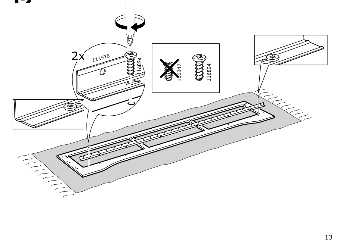
    Diagram for step 13: Two rail pieces are fixed onto the panel with screws, using the specified screw type while avoiding the crossed-out screw.
  20. Step 14

    The builder installs six screws (116894) into the long panel, with a callout indicating the correct screw type versus an incorrect one and a zoom showing screw seating detail.
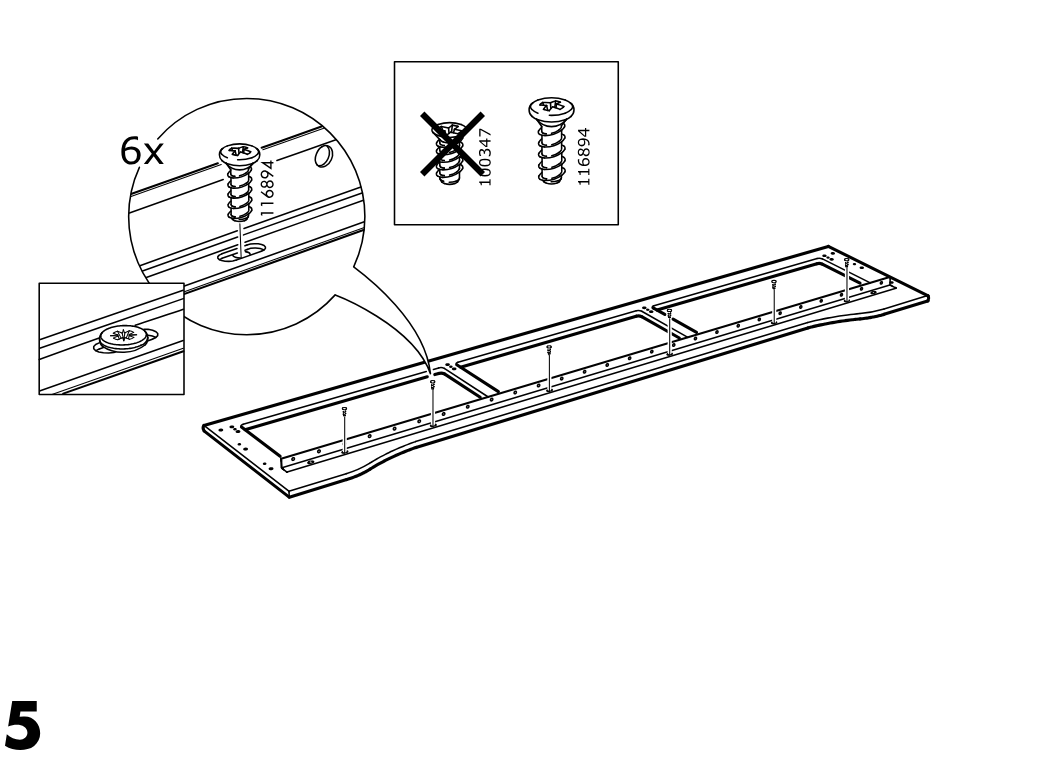
    Diagram for step 14: The builder installs six screws (116894) into the long panel, with a callout indicating the correct screw type versus an incorrect one and a zoom showing screw seating detail.
  21. Step 15

    The builder threads eight dowel bolts (118331) into predrilled holes along the same long panel, with a zoom callout showing correct insertion orientation.
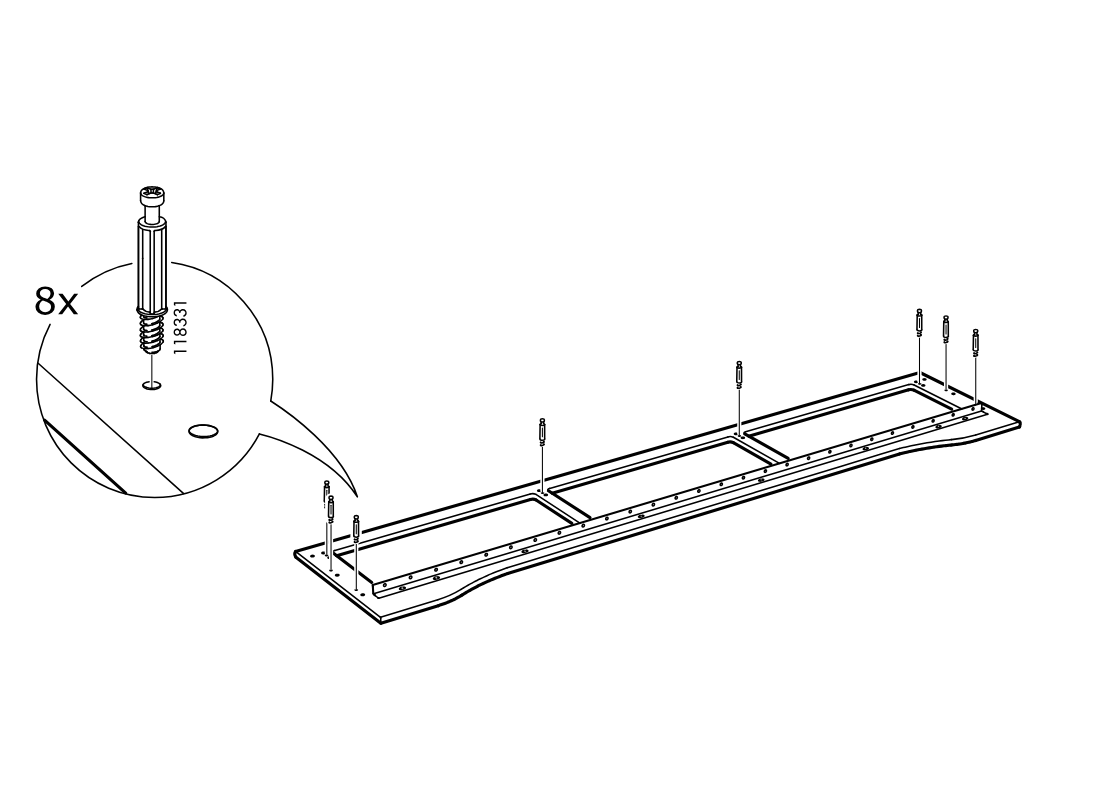
    Diagram for step 15: The builder threads eight dowel bolts (118331) into predrilled holes along the same long panel, with a zoom callout showing correct insertion orientation.
  22. Step 16

    The top panel is lowered onto the frame and aligned while a strap is pulled over it to secure position.
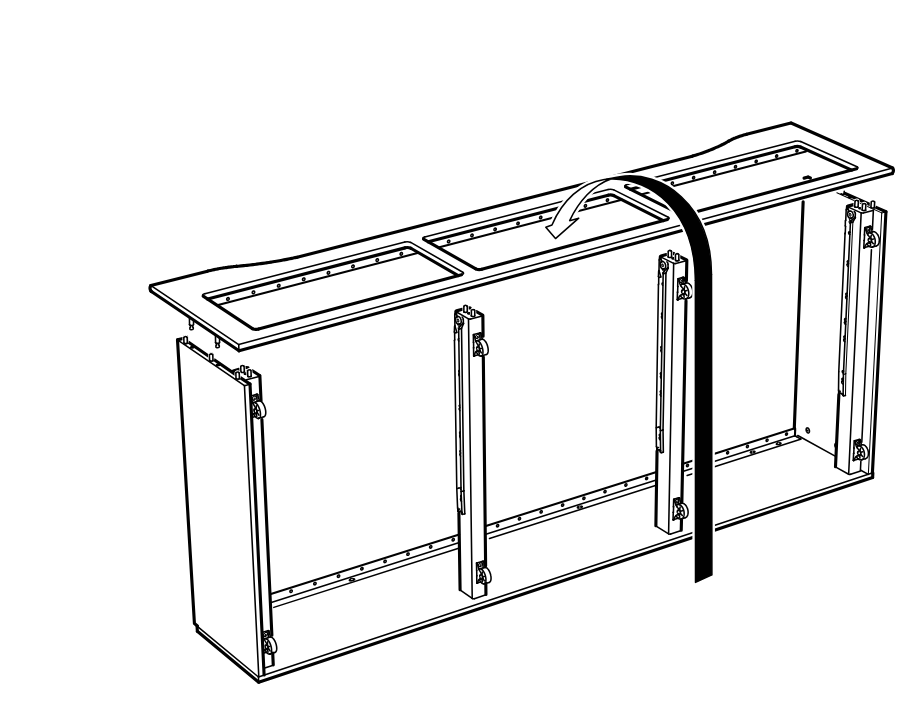
    Diagram for step 16: The top panel is lowered onto the frame and aligned while a strap is pulled over it to secure position.
  23. Step 17

    Four cam locks (103430) are inserted and turned with a screwdriver to lock the top panel to the frame.
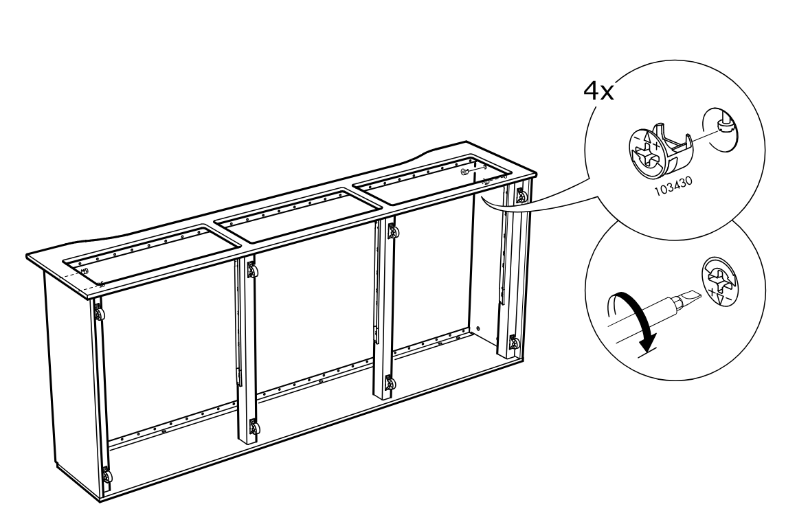
    Diagram for step 17: Four cam locks (103430) are inserted and turned with a screwdriver to lock the top panel to the frame.
  24. Step 18

    The cabinet frame is shown assembled while four cam locks (103430) are inserted and tightened with a screwdriver, with zoom callouts showing the hardware and turning direction.
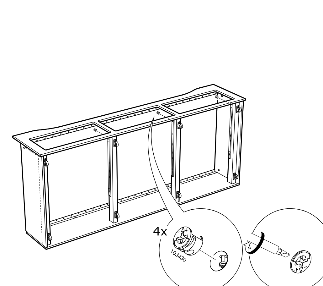
    Diagram for step 18: The cabinet frame is shown assembled while four cam locks (103430) are inserted and tightened with a screwdriver, with zoom callouts showing the hardware and turning direction.
  25. Step 19

    The assembler secures the lower rail to the vertical panels using six 116894 screws (not 100347), aligning positions marked 1, 2, and 3 as shown in the zoom inset.
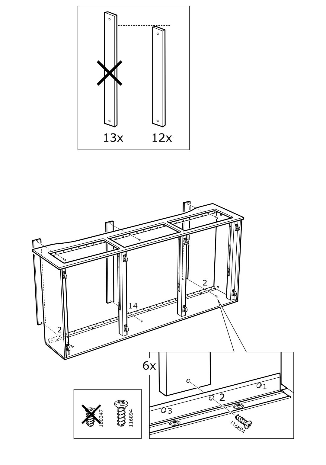
    Diagram for step 19: The assembler secures the lower rail to the vertical panels using six 116894 screws (not 100347), aligning positions marked 1, 2, and 3 as shown in the zoom inset.
  26. Step 20

    Eighteen fasteners are inserted into the ends of the slats, with a zoom callout showing the correct orientation of part 110525.
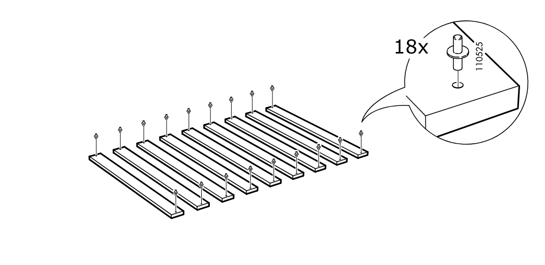
    Diagram for step 20: Eighteen fasteners are inserted into the ends of the slats, with a zoom callout showing the correct orientation of part 110525.
  27. Step 21

    The slatted base is folded down into the frame and aligned, then secured at eighteen points as shown in the zoomed connection detail.
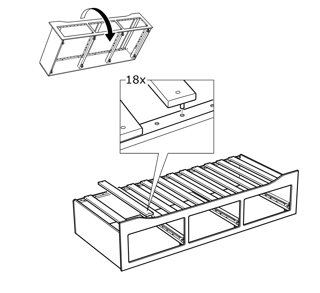
    Diagram for step 21: The slatted base is folded down into the frame and aligned, then secured at eighteen points as shown in the zoomed connection detail.
  28. Step 22

    The long rail is aligned along the slatted panel and fastened with two 116894 screws, with close-up callouts showing correct screw choice and edge orientation.
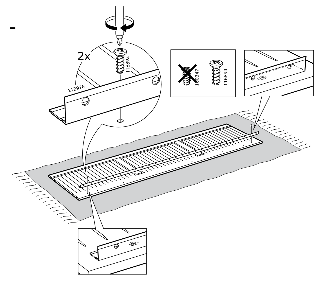
    Diagram for step 22: The long rail is aligned along the slatted panel and fastened with two 116894 screws, with close-up callouts showing correct screw choice and edge orientation.
  29. Step 23

    Insert six screws (116894) into the long panel edge holes, as shown in the zoom detail, and do not use screw 100347.
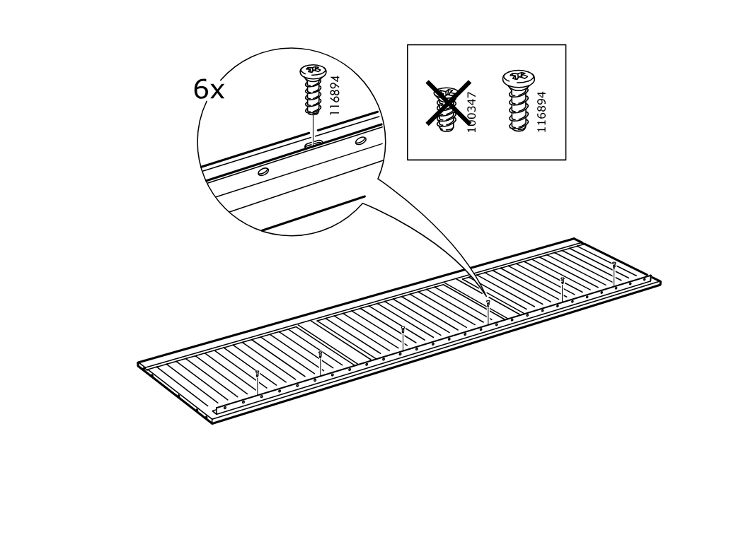
    Diagram for step 23: Insert six screws (116894) into the long panel edge holes, as shown in the zoom detail, and do not use screw 100347.
  30. Step 24

    Insert six dowels (101350) into the predrilled holes on the two smaller panels, three dowels per panel.
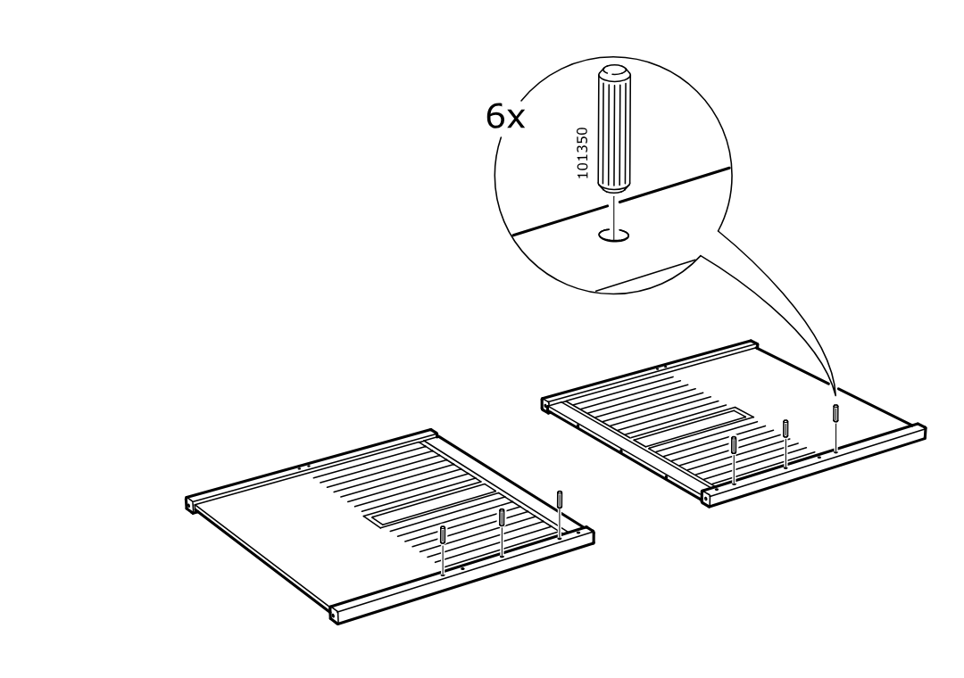
    Diagram for step 24: Insert six dowels (101350) into the predrilled holes on the two smaller panels, three dowels per panel.
  31. Step 25

    Attach the long side panel between the two end frames, rotate the cam locks (108203) at four points, and tighten the long bolts (105236) with the Allen key (100001).
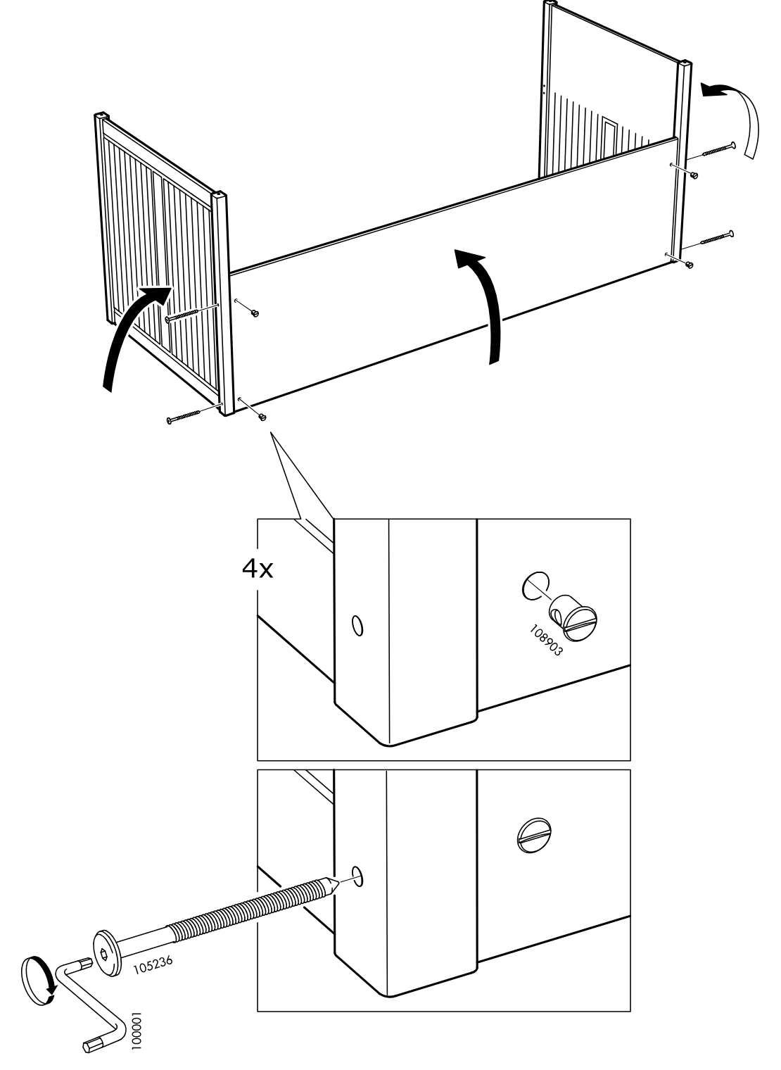
    Diagram for step 25: Attach the long side panel between the two end frames, rotate the cam locks (108203) at four points, and tighten the long bolts (105236) with the Allen key (100001).
  32. Step 26

    The side and front panels are aligned and four plug caps (153552) are pressed into the top post holes.
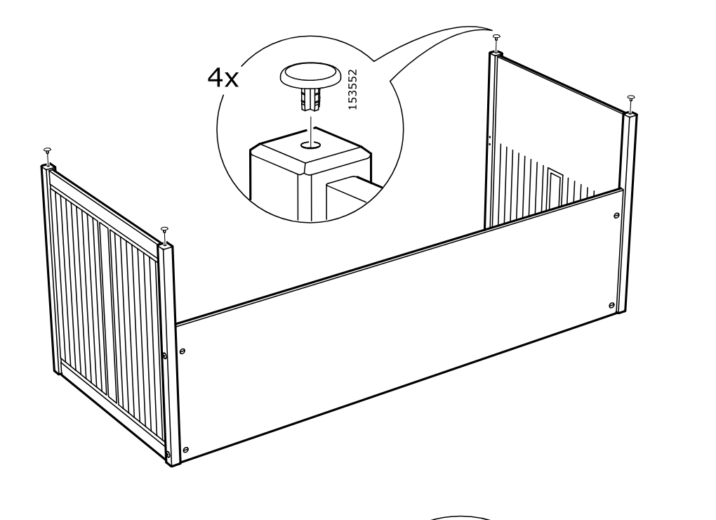
    Diagram for step 26: The side and front panels are aligned and four plug caps (153552) are pressed into the top post holes.
  33. Step 27

    Two screws (109060) are driven into part 130485 at the upper corner connection, using screw type 112978, while screw 116894 is explicitly marked as not to be used.
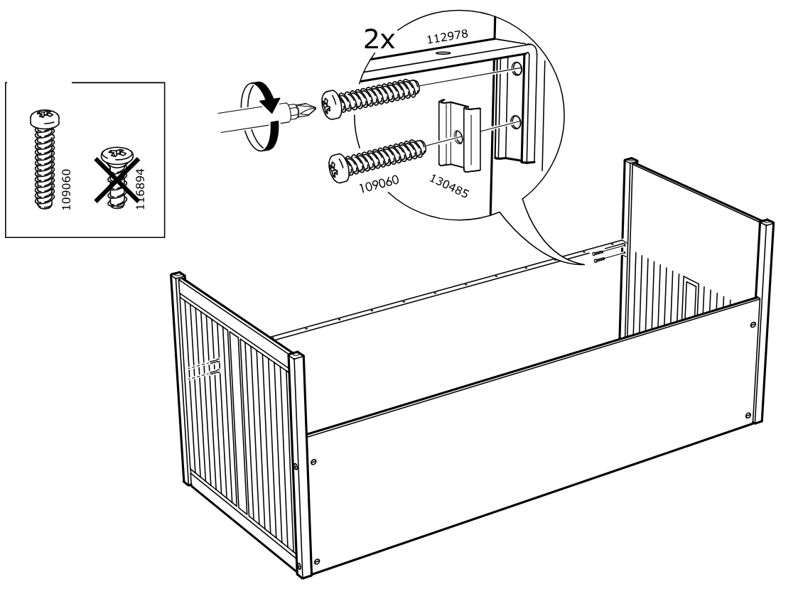
    Diagram for step 27: Two screws (109060) are driven into part 130485 at the upper corner connection, using screw type 112978, while screw 116894 is explicitly marked as not to be used.
  34. Before you begin

    Panel shows flipping the crib/body assembly orientation before continuing.
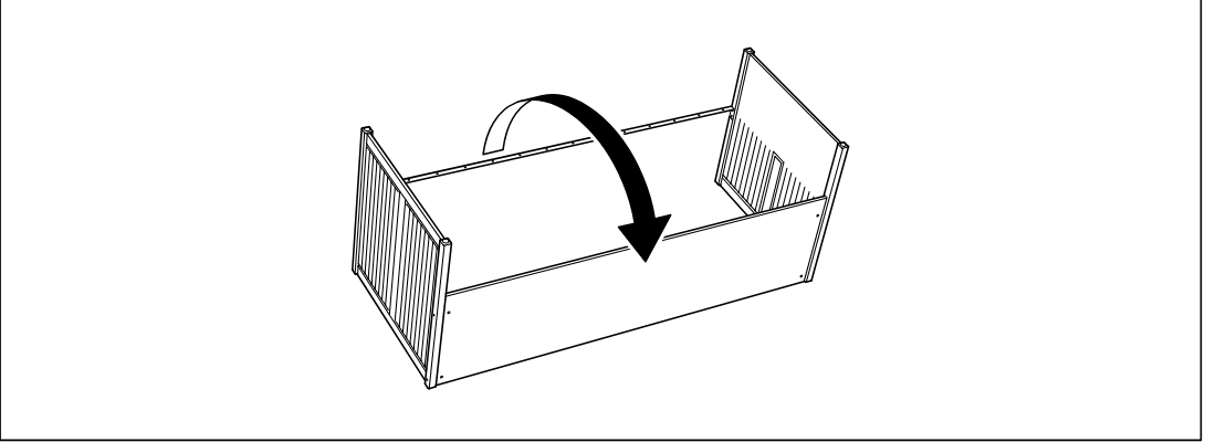
    Illustration for assembly note: Panel shows flipping the crib/body assembly orientation before continuing.
  35. Step 28

    Select the two correct side rails, then fasten bracket 123660 to each rail end using two 116894 screws per rail as shown in the zoom detail.
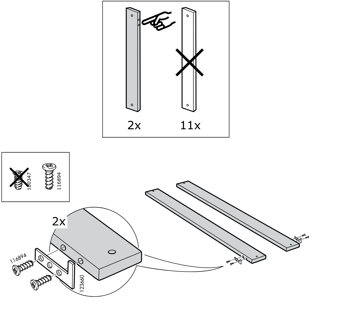
    Diagram for step 28: Select the two correct side rails, then fasten bracket 123660 to each rail end using two 116894 screws per rail as shown in the zoom detail.
  36. Step 29

    Install two 116894 screws to secure the side rail/frame corners while supporting the lower panel from underneath, using the detailed corner close-ups for alignment and screw choice.
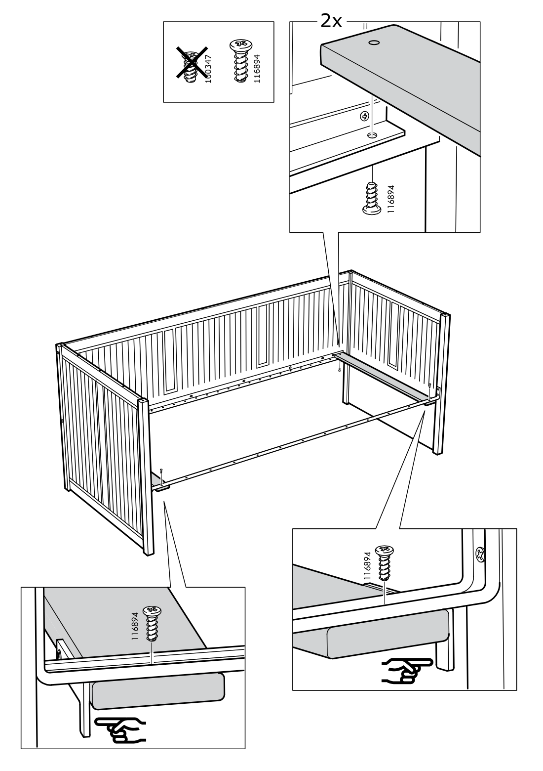
    Diagram for step 29: Install two 116894 screws to secure the side rail/frame corners while supporting the lower panel from underneath, using the detailed corner close-ups for alignment and screw choice.
  37. Step 30

    Insert eleven 110525 pins into the bed slats as shown, one pin per slat.
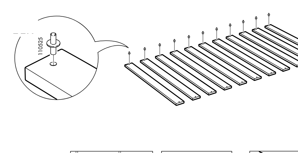
    Diagram for step 30: Insert eleven 110525 pins into the bed slats as shown, one pin per slat.
  38. Step 31

    Place the slats into the bed frame and fasten them with eleven 116894 screws (not 103347), then keep the bed unloaded as indicated by the crossed-out standing warning.
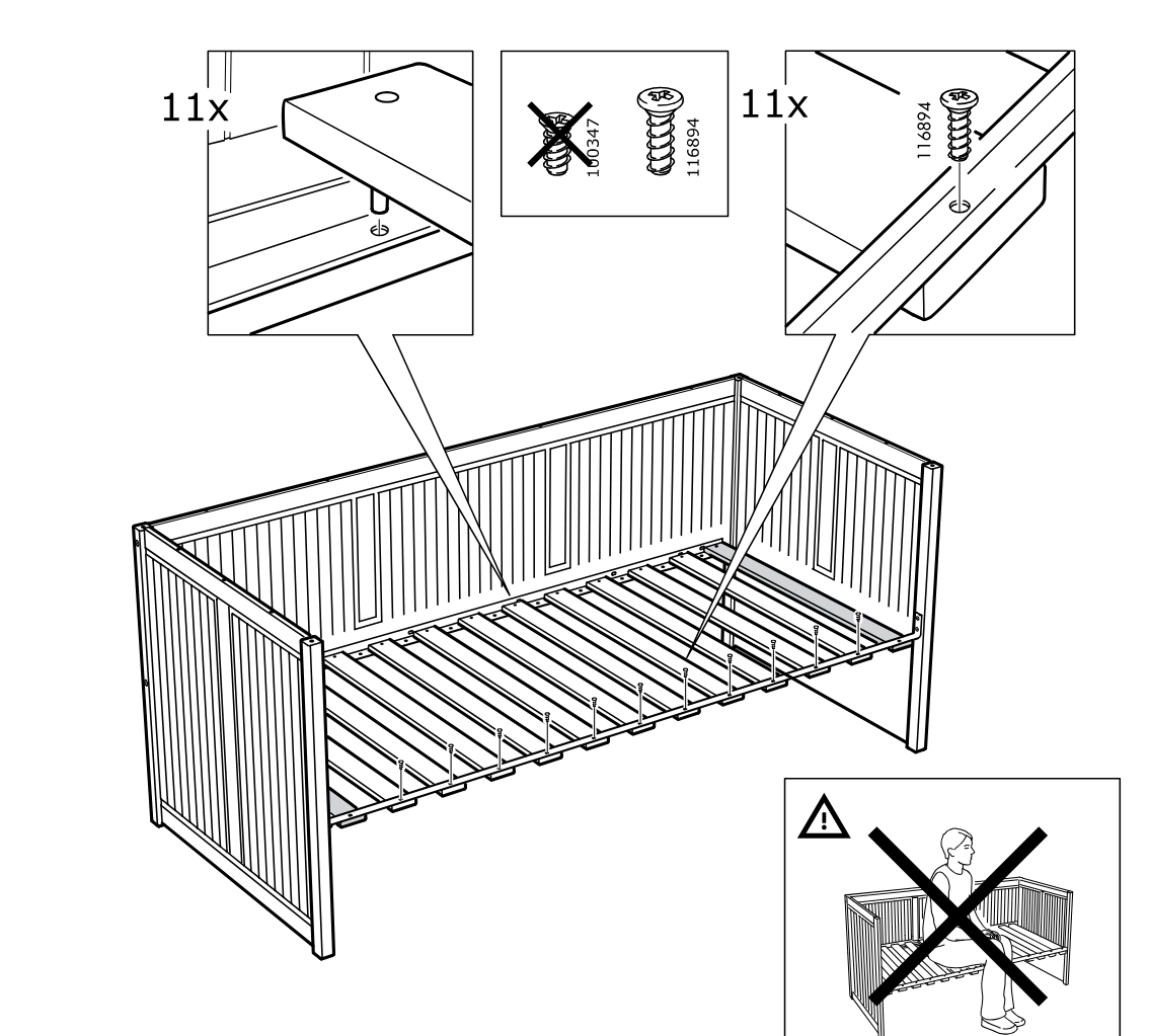
    Diagram for step 31: Place the slats into the bed frame and fasten them with eleven 116894 screws (not 103347), then keep the bed unloaded as indicated by the crossed-out standing warning.
  39. Step 32

    Two people position and slide the bed sections together, then align and secure the inner rail connection points shown in the enlarged callouts.
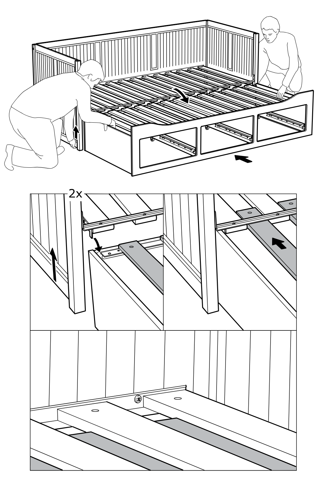
    Diagram for step 32: Two people position and slide the bed sections together, then align and secure the inner rail connection points shown in the enlarged callouts.
  40. Step 33

    Thread 17 cam screws into the top rail holes around the bed frame and tap them down with a hammer as shown in the zoom callout.
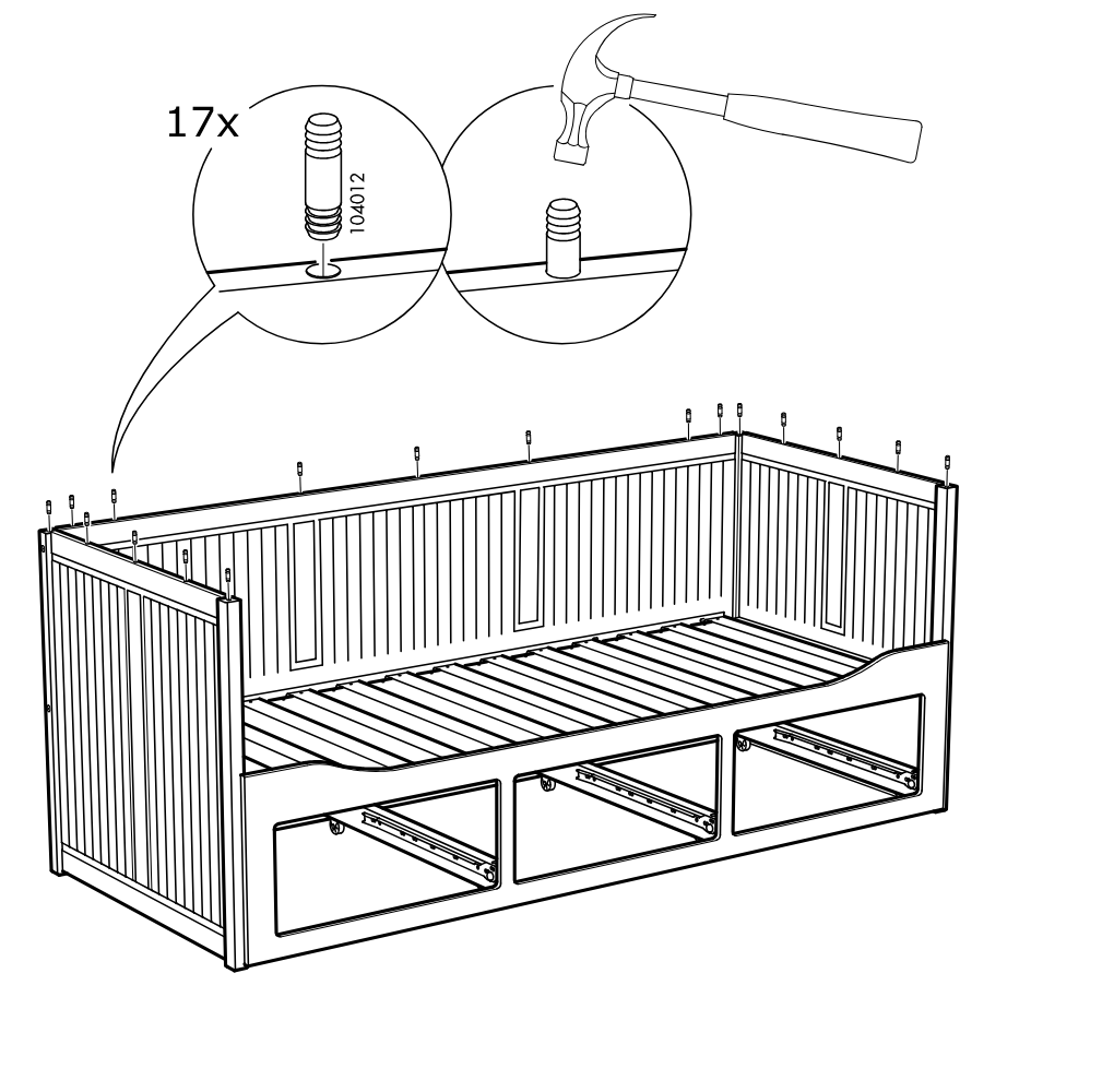
    Diagram for step 33: Thread 17 cam screws into the top rail holes around the bed frame and tap them down with a hammer as shown in the zoom callout.
  41. Step 34

    Two long top rails are positioned and lowered onto the upper edges of the bed frame.
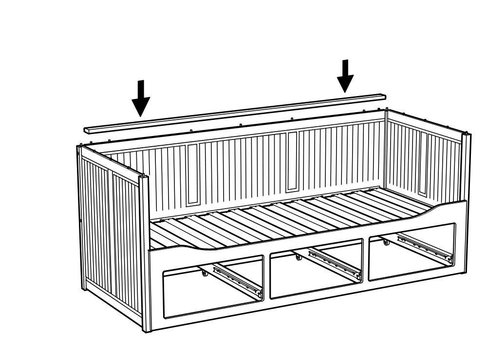
    Diagram for step 34: Two long top rails are positioned and lowered onto the upper edges of the bed frame.
  42. Step 35

    Two people align each long rail’s end orientation with the corner posts and press the rails down into place along both top sides.
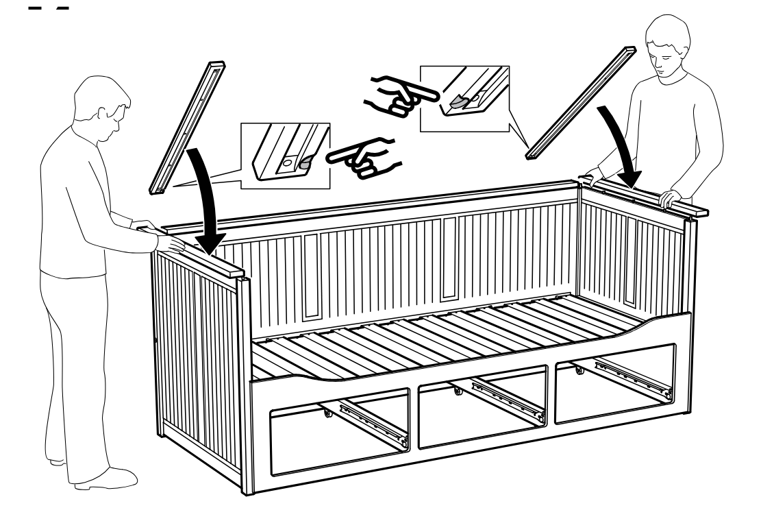
    Diagram for step 35: Two people align each long rail’s end orientation with the corner posts and press the rails down into place along both top sides.
  43. Step 36

    The side panels are connected to the bottom panel using four cam locks, then the cams are tightened with a screwdriver as shown in the zoom callouts.
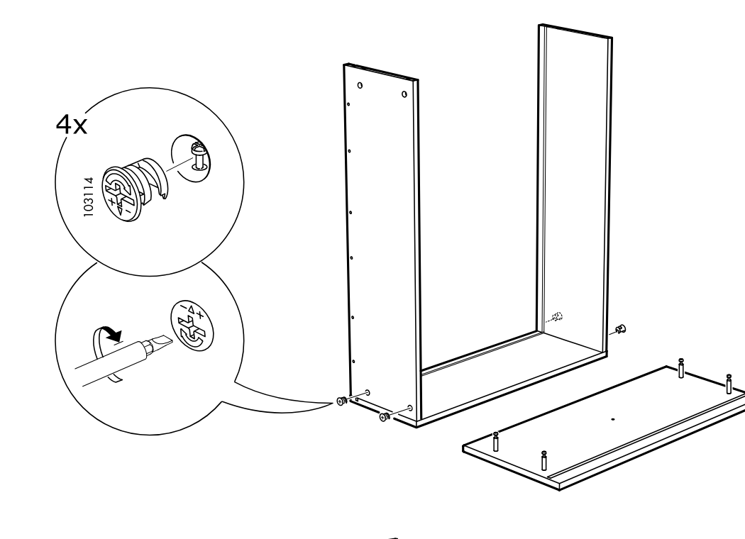
    Diagram for step 36: The side panels are connected to the bottom panel using four cam locks, then the cams are tightened with a screwdriver as shown in the zoom callouts.
  44. Step 37

    The back panel is lowered straight down into the grooves of the assembled side and bottom frame.
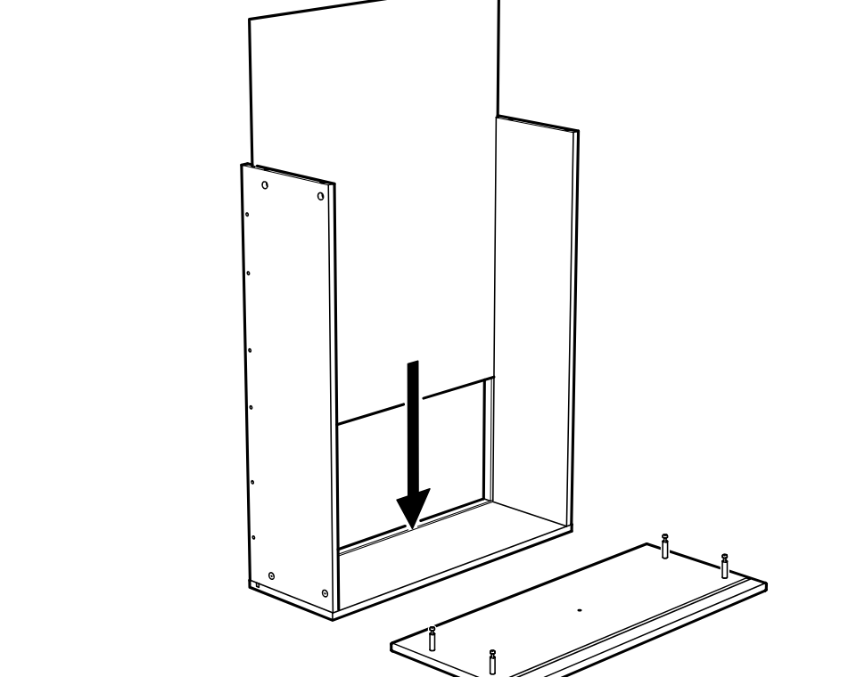
    Diagram for step 37: The back panel is lowered straight down into the grooves of the assembled side and bottom frame.
  45. Step 38

    The top panel is lowered onto the cabinet frame, guided by a large curved arrow to align with the corner posts.
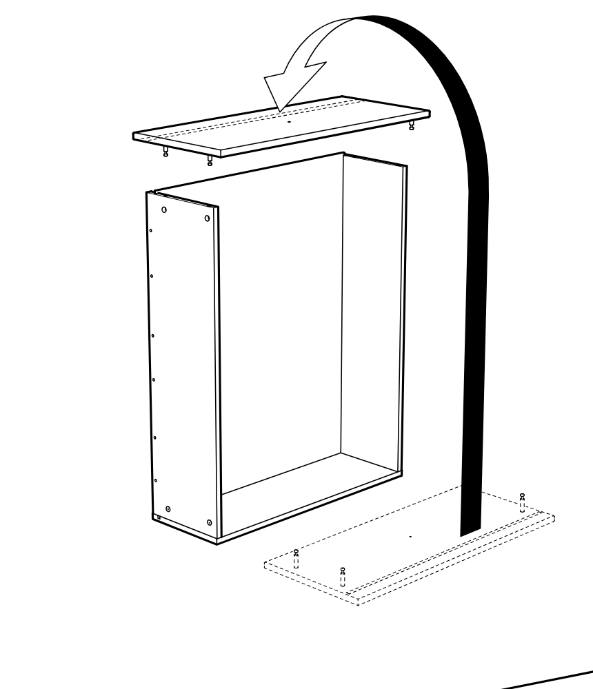
    Diagram for step 38: The top panel is lowered onto the cabinet frame, guided by a large curved arrow to align with the corner posts.
  46. Step 39

    Four cam locks (103114) are inserted and then turned with a screwdriver to secure the top panel to the cabinet sides.
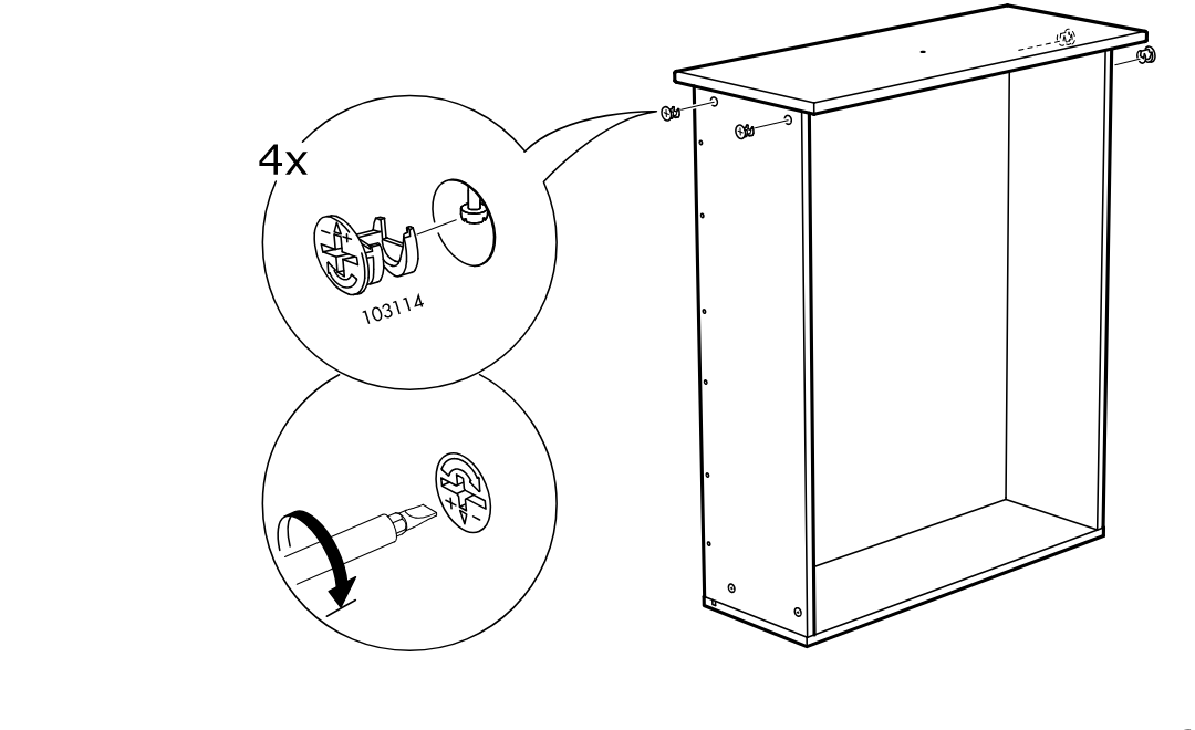
    Diagram for step 39: Four cam locks (103114) are inserted and then turned with a screwdriver to secure the top panel to the cabinet sides.
  47. Step 40

    Attach the two rail pieces to the drawer assembly using three screws (103347) on each side, with orientation differing for DR and DL.
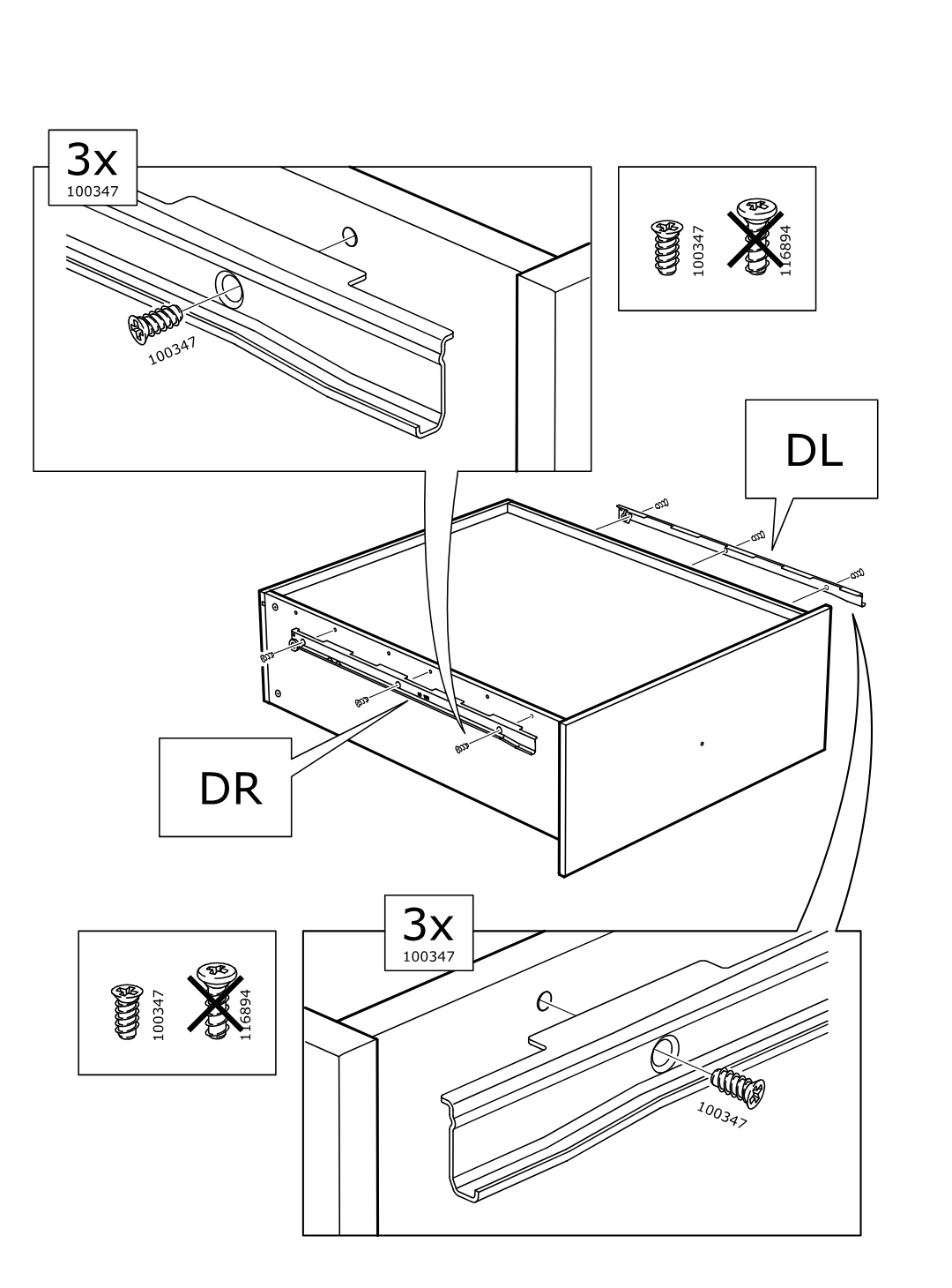
    Diagram for step 40: Attach the two rail pieces to the drawer assembly using three screws (103347) on each side, with orientation differing for DR and DL.
  48. Step 41

    A knob and screw are aligned and fastened to the cabinet top panel using the shown hardware orientation.
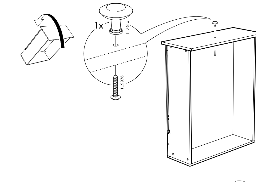
    Diagram for step 41: A knob and screw are aligned and fastened to the cabinet top panel using the shown hardware orientation.
  49. Step 42

    A person pulls out the right drawer of the bed/daybed, while an inline caution box shows not to use an open drawer as a step.
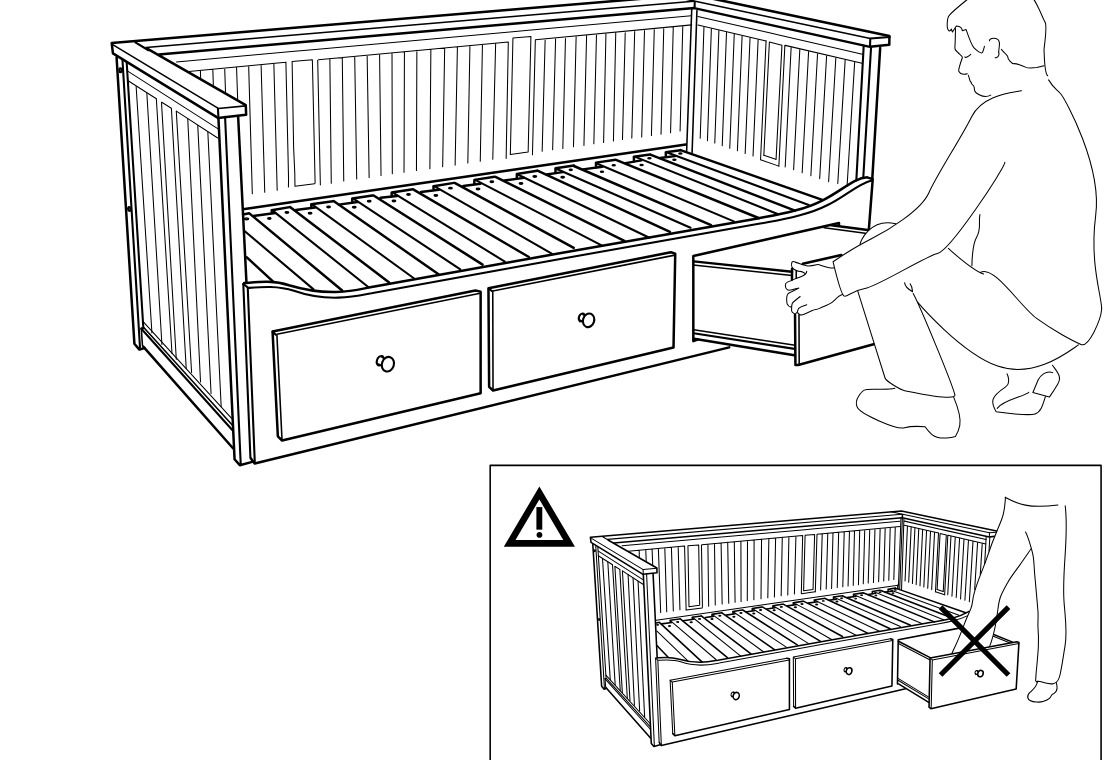
    Diagram for step 42: A person pulls out the right drawer of the bed/daybed, while an inline caution box shows not to use an open drawer as a step.
  50. Before you begin

    A standalone information panel shows correct and incorrect rug placement under the daybed: the top illustration is acceptable and the bottom illustration is crossed out as not acceptable.
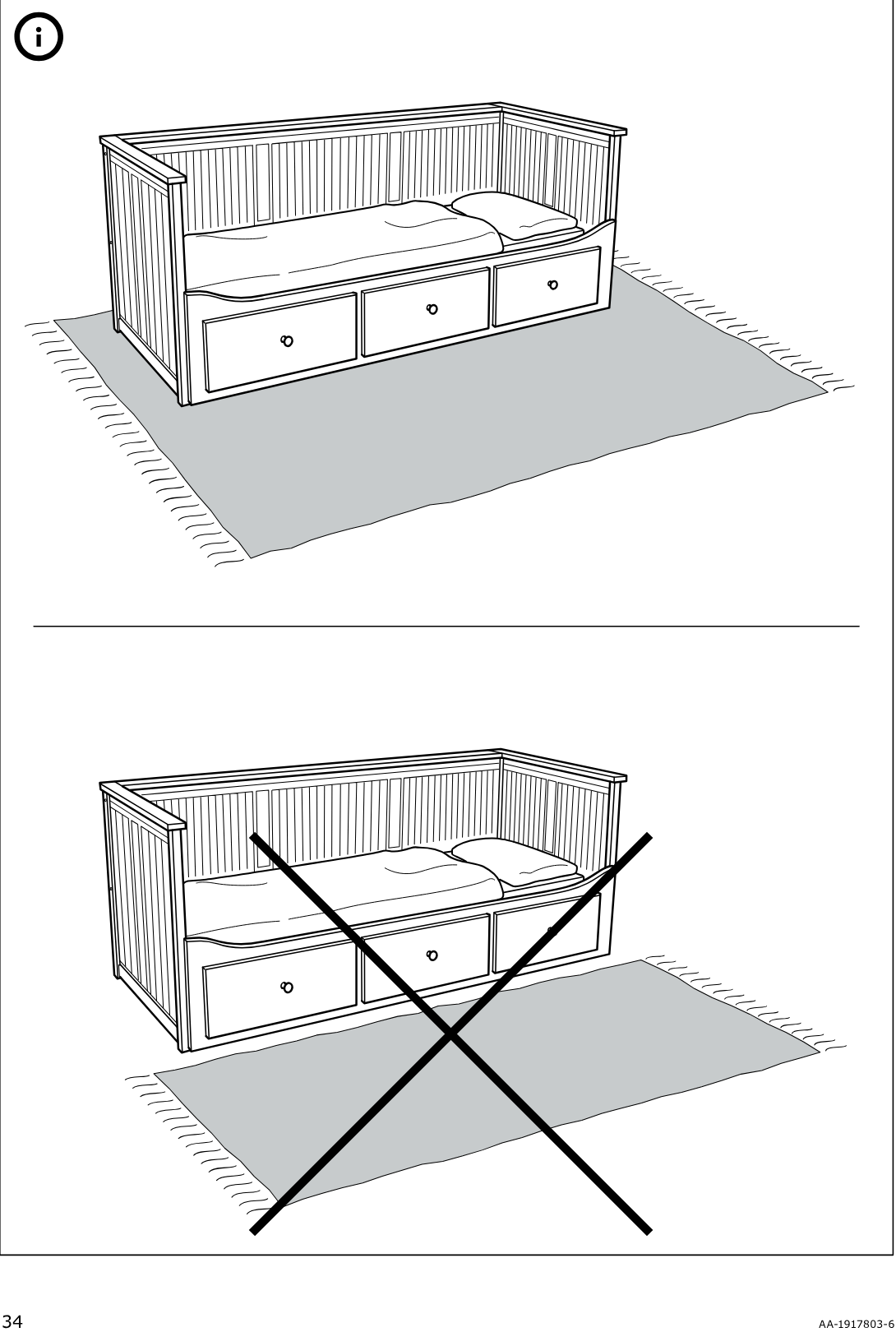
    Illustration for assembly note: A standalone information panel shows correct and incorrect rug placement under the daybed: the top illustration is acceptable and the bottom illustration is crossed out as not acceptable.

Make it yours

Small additions. A better setup.

These optional additions are separate from any parts, safety equipment, or tools required to assemble the product.

Browse organization ideas

Some links are affiliate links. We may earn a commission if you buy through them, at no extra cost to you. As an Amazon Associate, we earn from qualifying purchases.

  • madesmart 5-compartment tray, white

    A shallow tray sorts small supplies in a HEMNES daybed drawer.

    The 12.75 × 9 × 1.88 in tray fits within IKEA’s listed 20⅛ × 27½ × 7⅛ in drawer interior. Lay it flat and check that the drawer closes freely.

    View product

Video guide