IDANÄS Bed frame
Before you begin
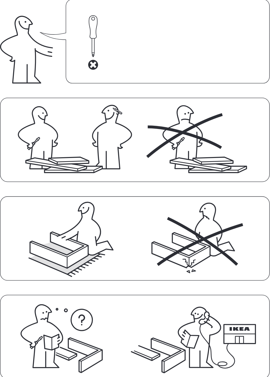
Safety/preparation panels show to use a manual screwdriver (not power driver), assemble with two people, assemble on a soft surface/rug (not directly on hard floor), and contact IKEA support if unsure.
Before you begin
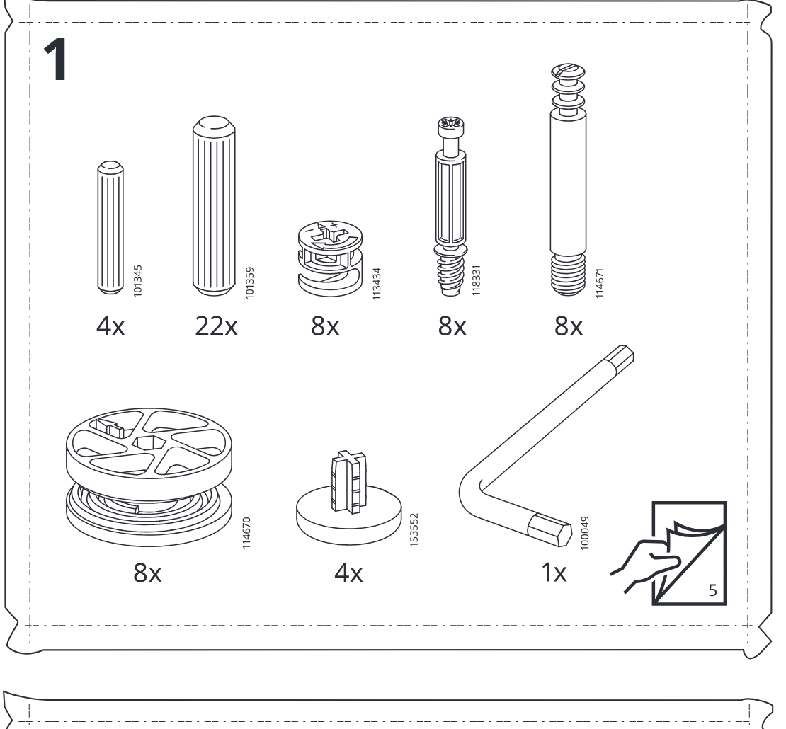
Parts-bag panel 1 showing hardware items with quantities and part numbers, plus note to use bag 5.
Before you begin
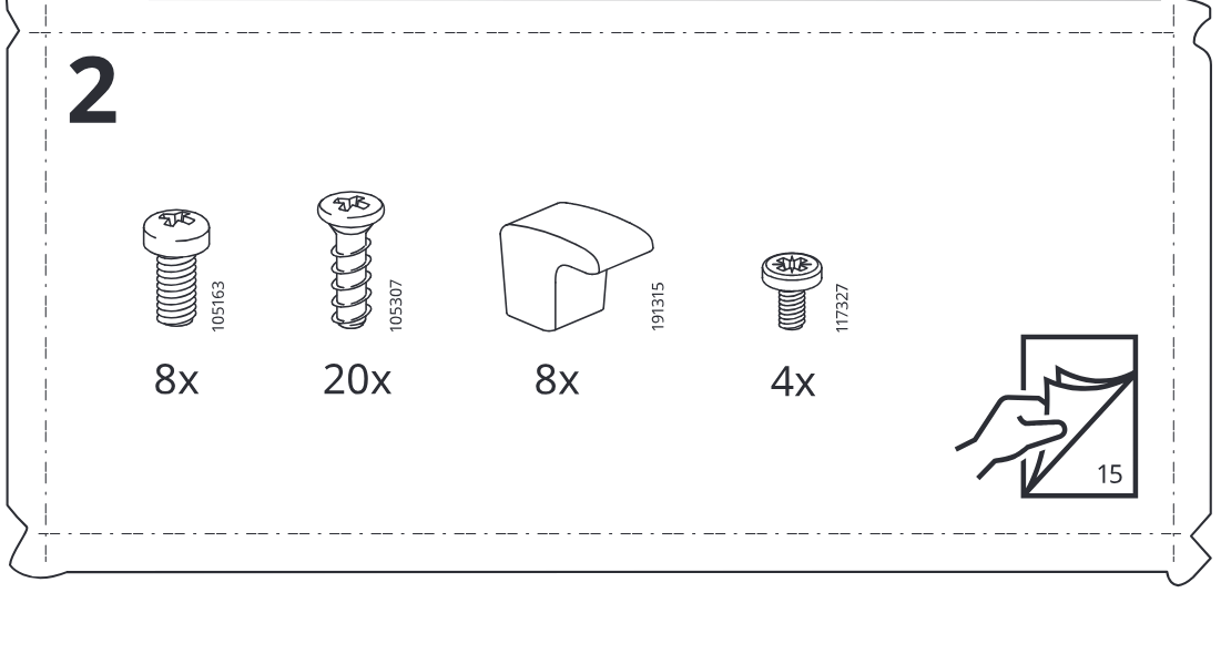
Parts-bag panel 2 showing hardware items with quantities and part numbers, plus note to use bag 15.
Before you begin
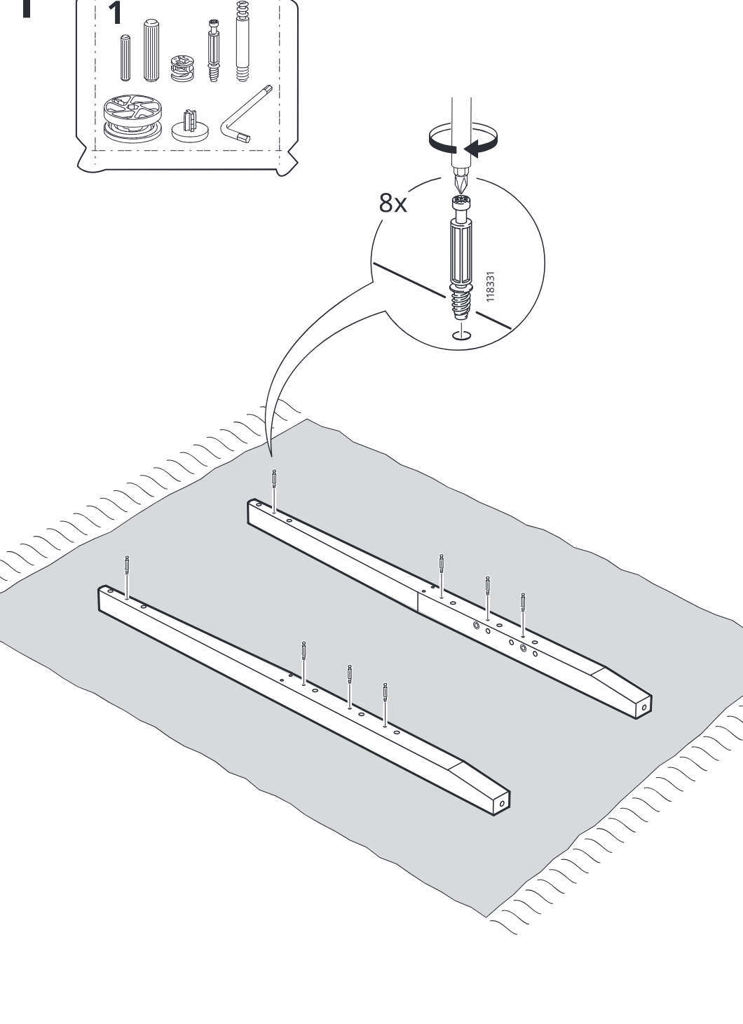
Parts-bag reference panel for bag 1 shows installing eight 118331 threaded studs with a screwdriver into the two long frame rails placed on a soft surface.
Step 2
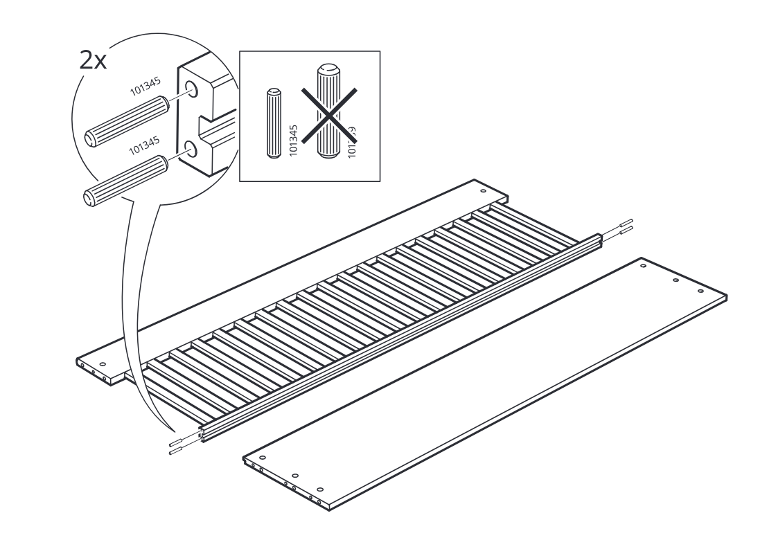
Two 101345 dowels are inserted into the side panel holes, with an inline comparison box indicating the correct dowel length.
Step 3
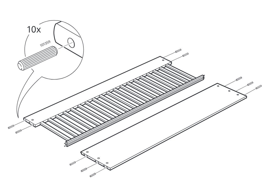
Ten 101359 dowels are inserted into the indicated holes across both long panels around the slatted center section.
Step 4
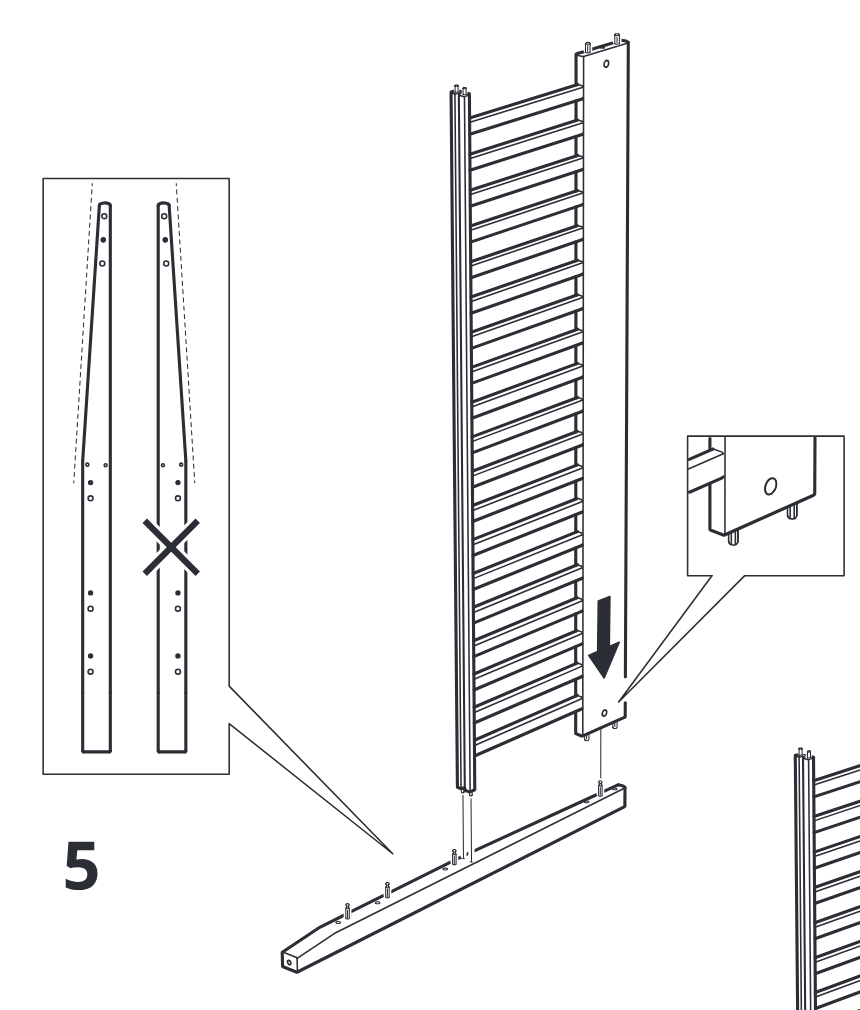
The side ladder frame is aligned and lowered onto the bottom rail with the correct orientation, with inset callouts showing the peg alignment and forbidden reversed orientation.
Step 5
A cam lock (part 113434) is inserted and tightened with a screwdriver to secure the assembled frame to the bottom rail, as shown by the circular zooms and rotation arrow.
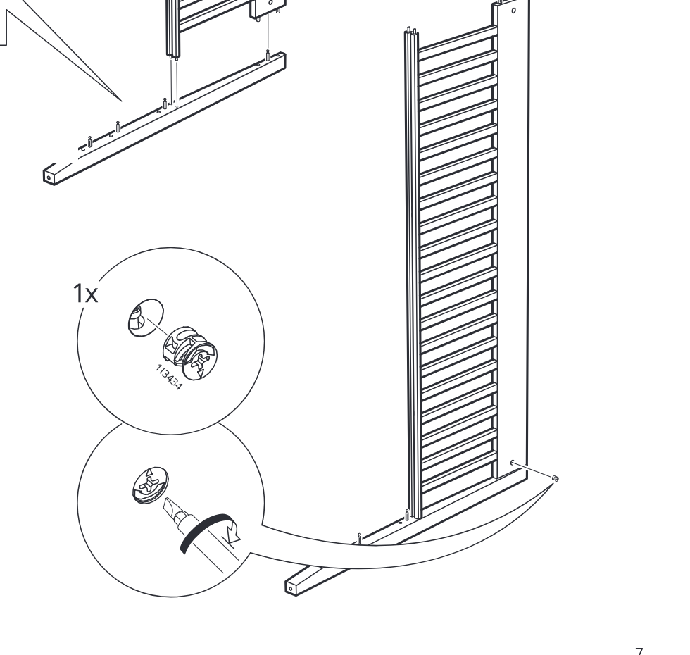
Step 6
The side panel is lowered onto the frame and aligned with the top dowel orientation shown in the zoom callout.
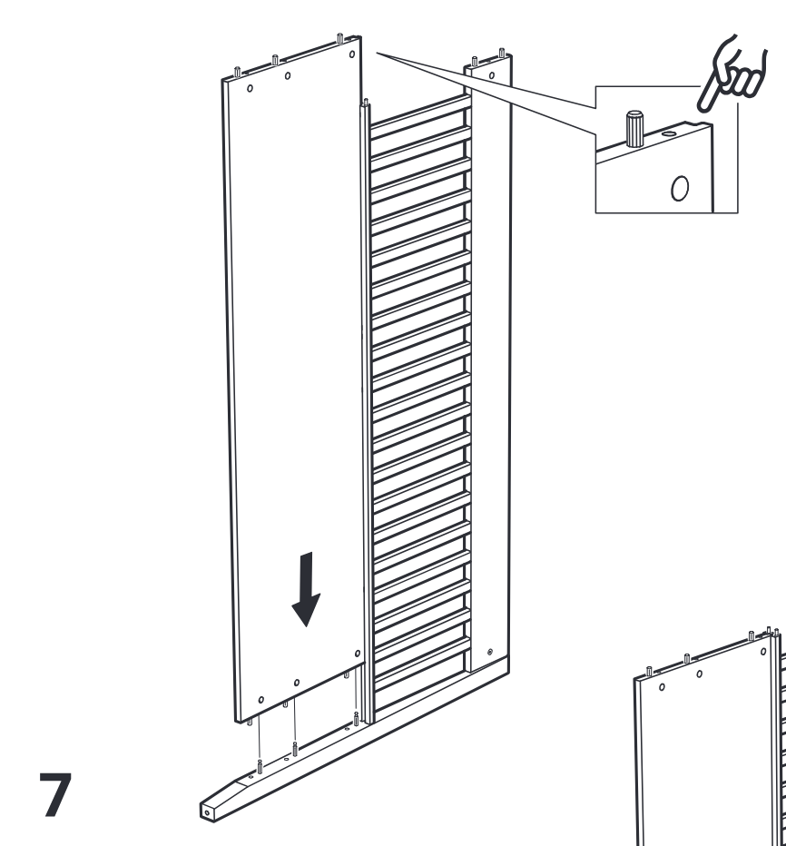
Step 7
The second bottom rail is positioned and secured with three cam locks, then tightened as shown in the two circular zoom callouts.
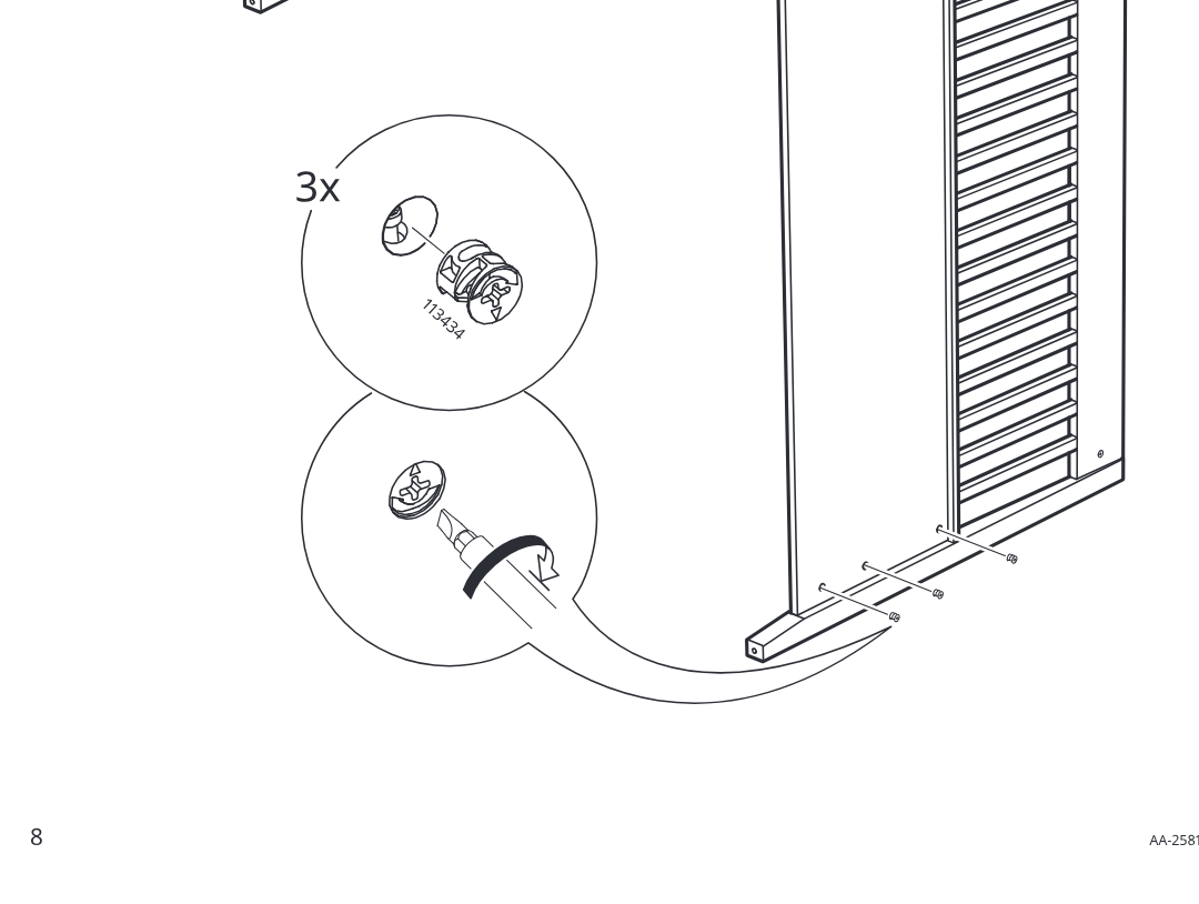
Step 8
The top rail is placed onto the frame, four cam locks (113434) are inserted and tightened, and the assembly is then rotated to a new orientation.
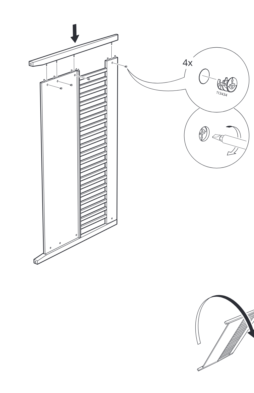
Step 9
The installer screws eight threaded studs into the marked holes on both side-frame panel assemblies.
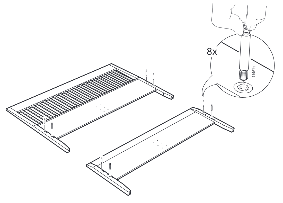
Step 10
The installer pushes four round caps into the side-frame end holes on the two panel assemblies.
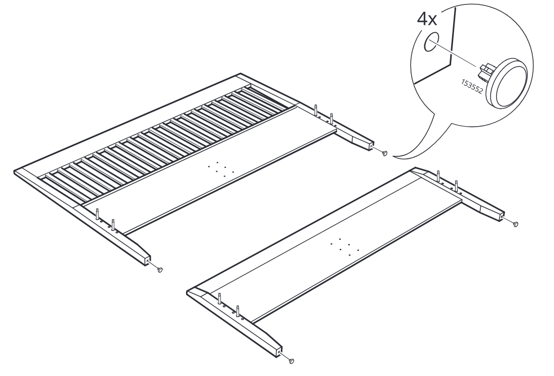
Step 11
Insert twelve dowels (101359) into the end holes of the two long panels, six per panel.
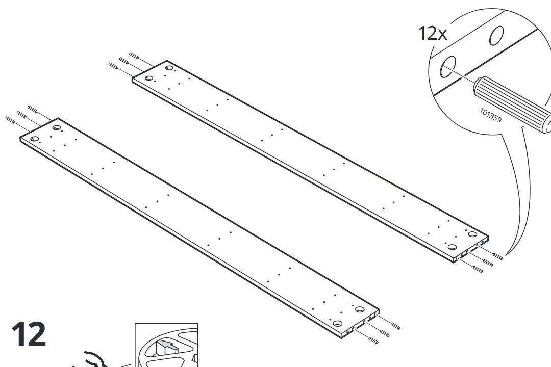
Step 12
Press four cam locks (114670) into the large circular holes on each long panel with the arrow orientation set as shown in the zoom callouts.
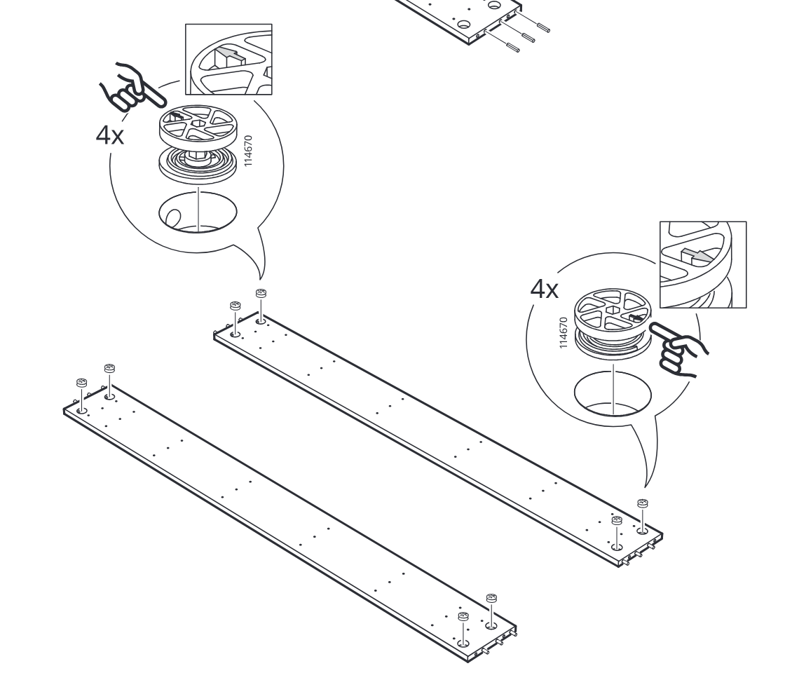
Step 13
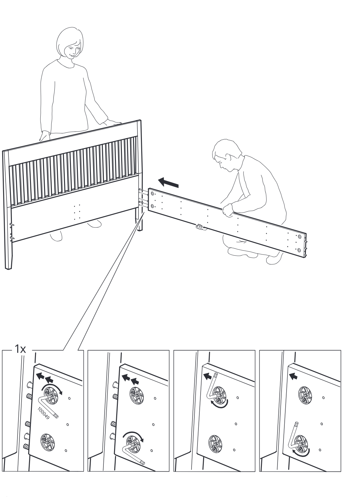
Two people align the long side rail with the headboard and lock the cam fittings, as shown in the four close-up panels.
Step 14
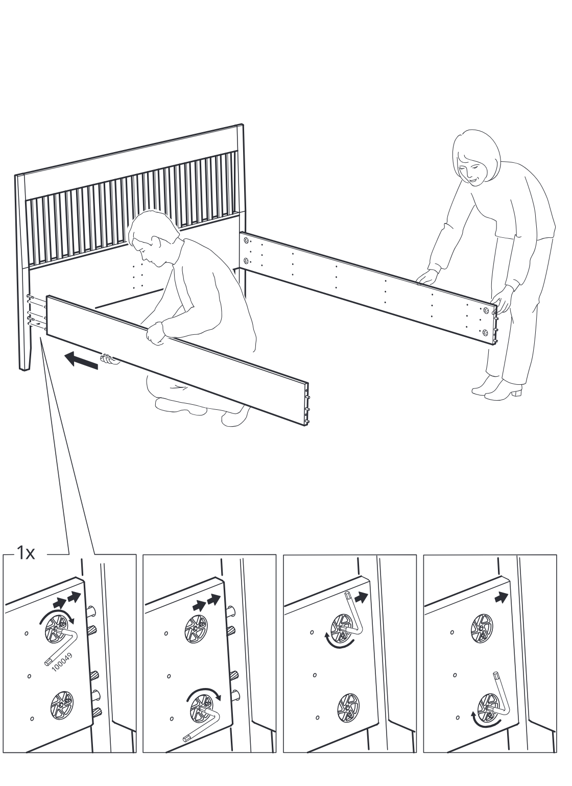
Two people align and slide the side panels into the headboard connectors, then lock the cam fasteners as shown in the four inline tightening diagrams.
Step 15
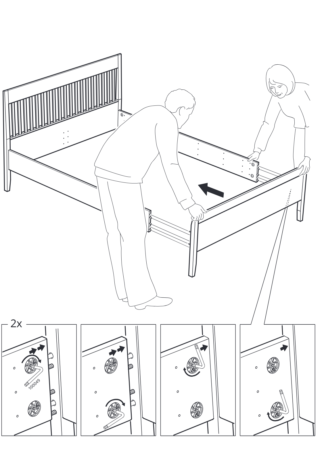
Two people slide the bed side assembly into position and secure the cam locks on both sides using the included hex key, repeating the lock sequence 2 times as shown in the four inset panels.
Step 16
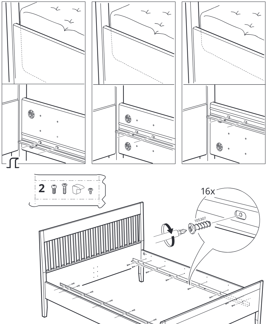
The side rails are aligned and secured to the bed frame with 16 screws, with a zoom callout showing screw 105307 being driven into the rail insert.
Step 17
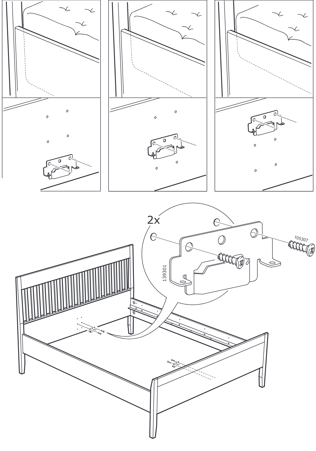
The bracket part 139301 is positioned on the inner side area and fixed using two screws 105307, with the zoom callout showing screw placement details.
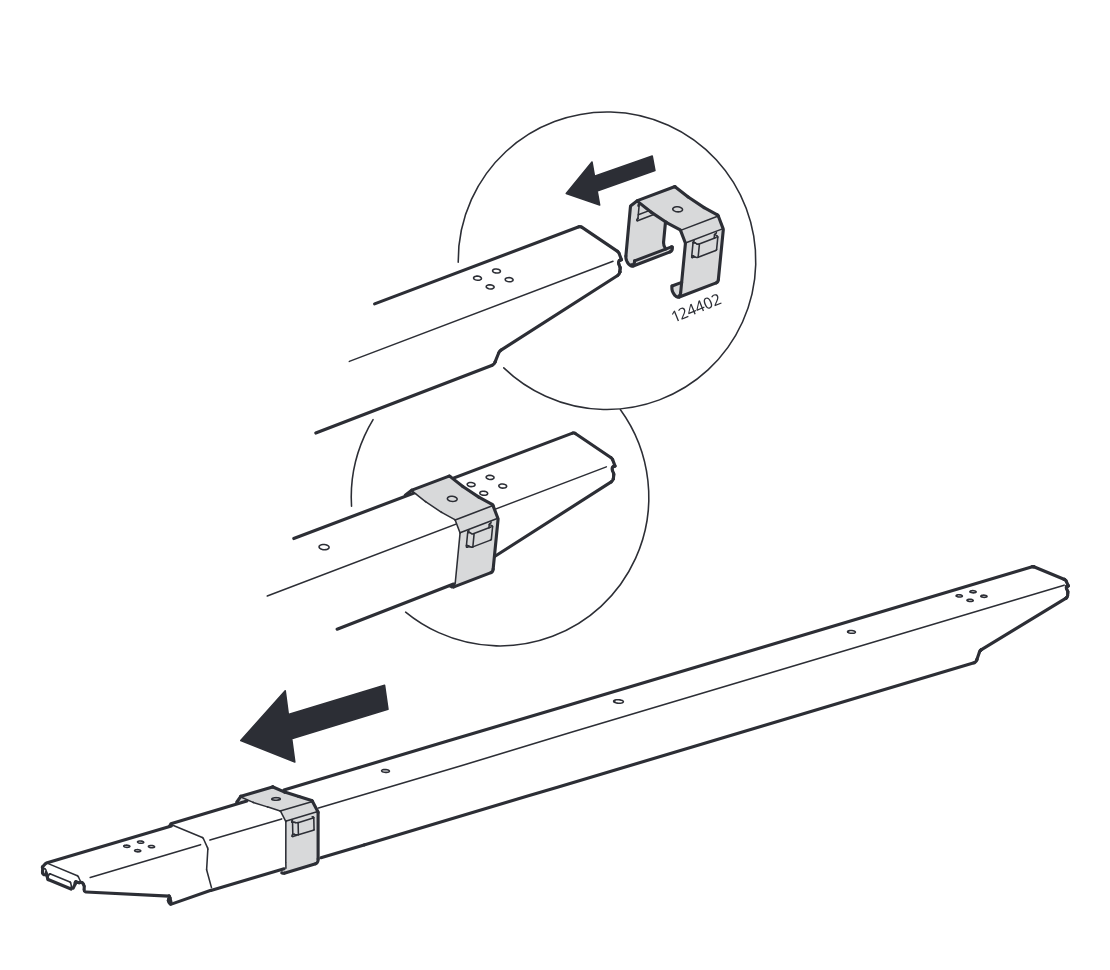
Step 18
The clip part 124402 is placed onto the rail end and the clip is slid leftward along the rail into position, as shown in the two zoom callouts and the main assembly view.
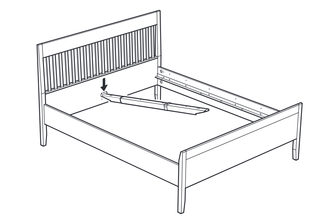
Step 19
The strap assembly is positioned and connected at the left-side mounting point inside the bed frame.
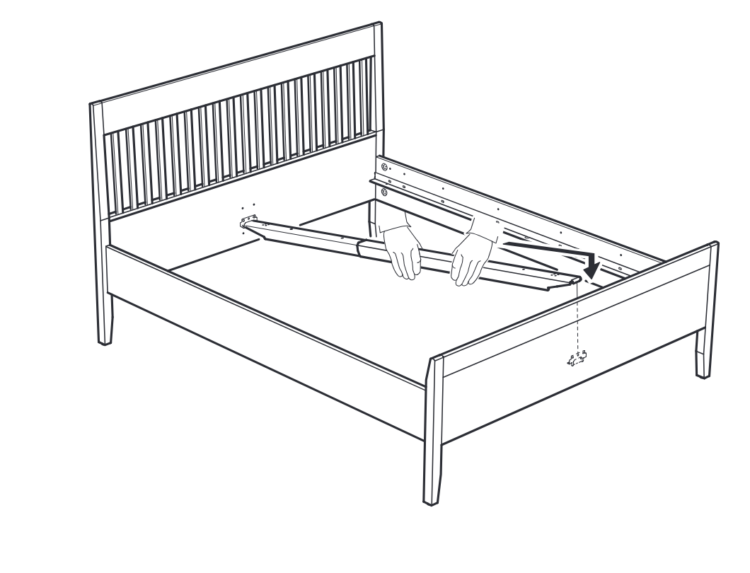
Step 20
The strap assembly is pulled and routed toward the right side while the small end fitting aligns with and fastens to the footboard area.
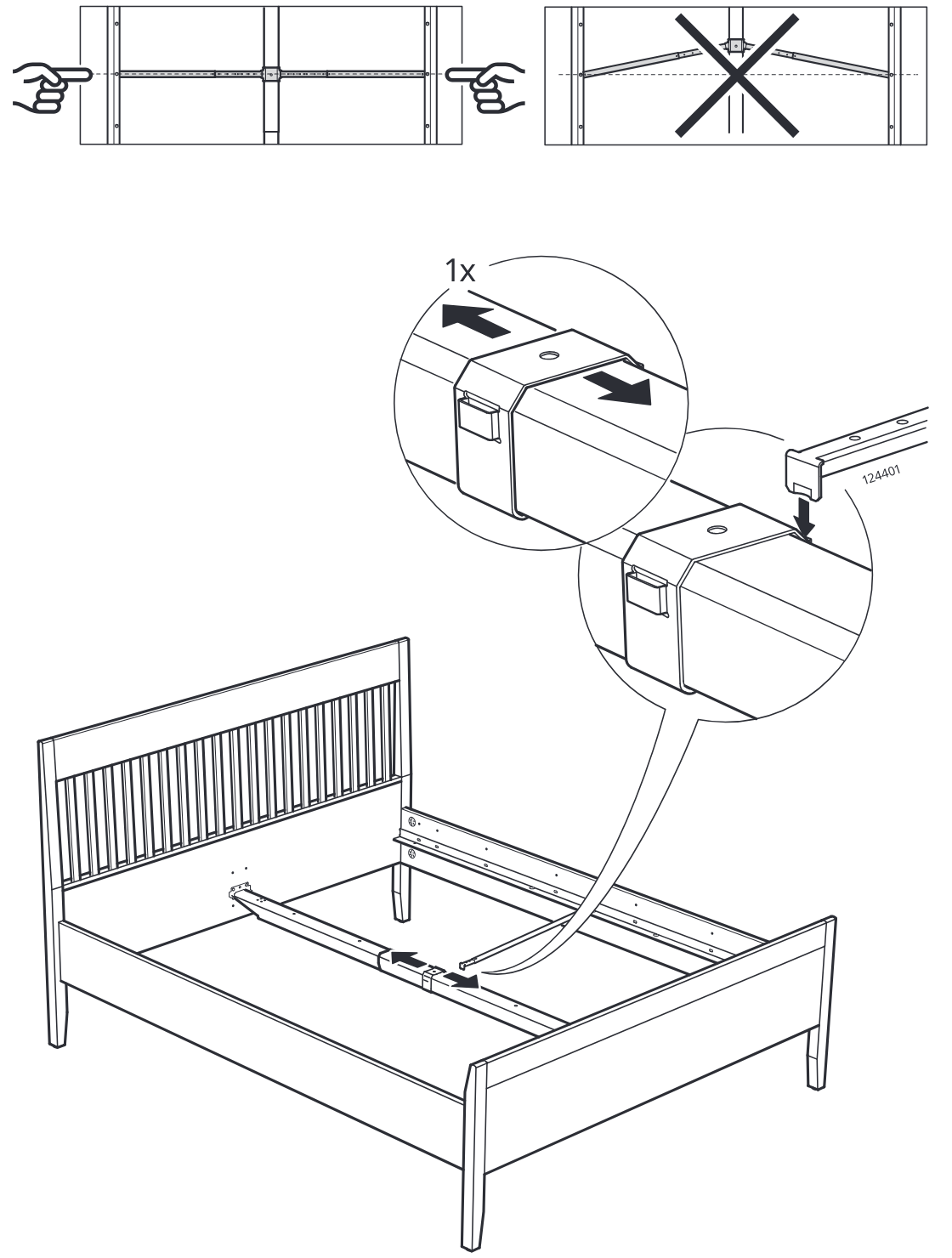
Step 21
The center support rail is aligned straight and then locked with one 124401 clip onto the rail connection, as shown in the zoom callouts.
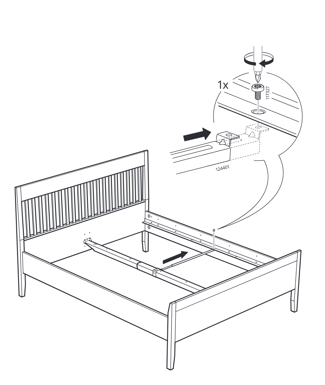
Step 22
The center support rail is positioned and secured to the bed frame using one screw tightened with a screwdriver, as shown in the zoomed inset.
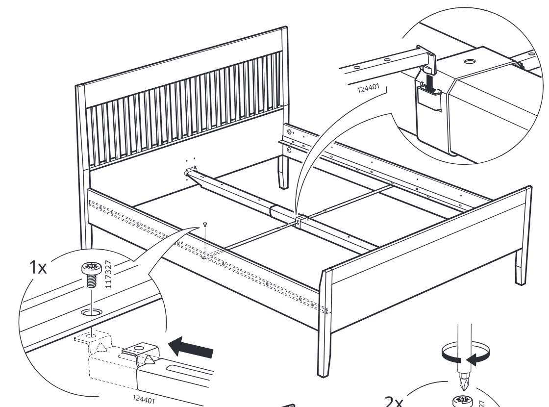
Step 23
Slide the center rail bracket into position on the frame and fasten one screw 117327 through the rail while ensuring the connector 124401 is seated correctly.
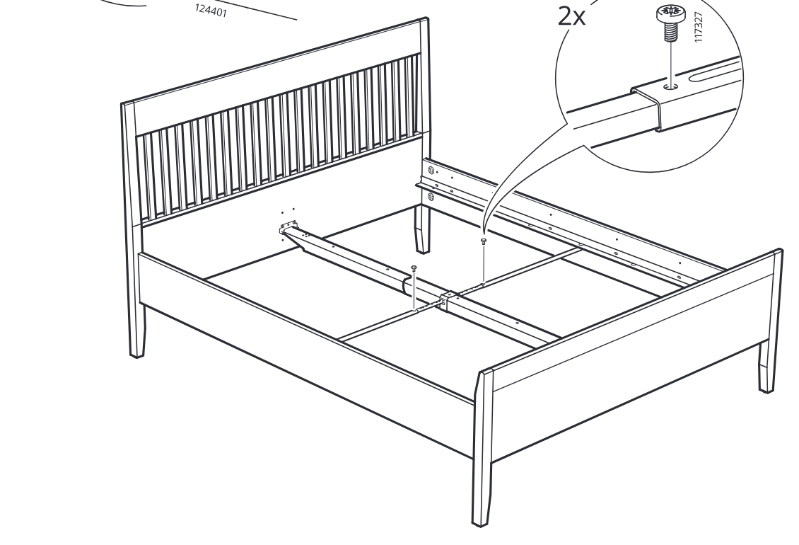
Step 24
Insert and tighten two screws 117327 into the center rail joint area to secure the rail connection.
Before you begin
A standalone circled-i panel shows two alternative slat base configurations and indicates to continue to page 23 for one variant.
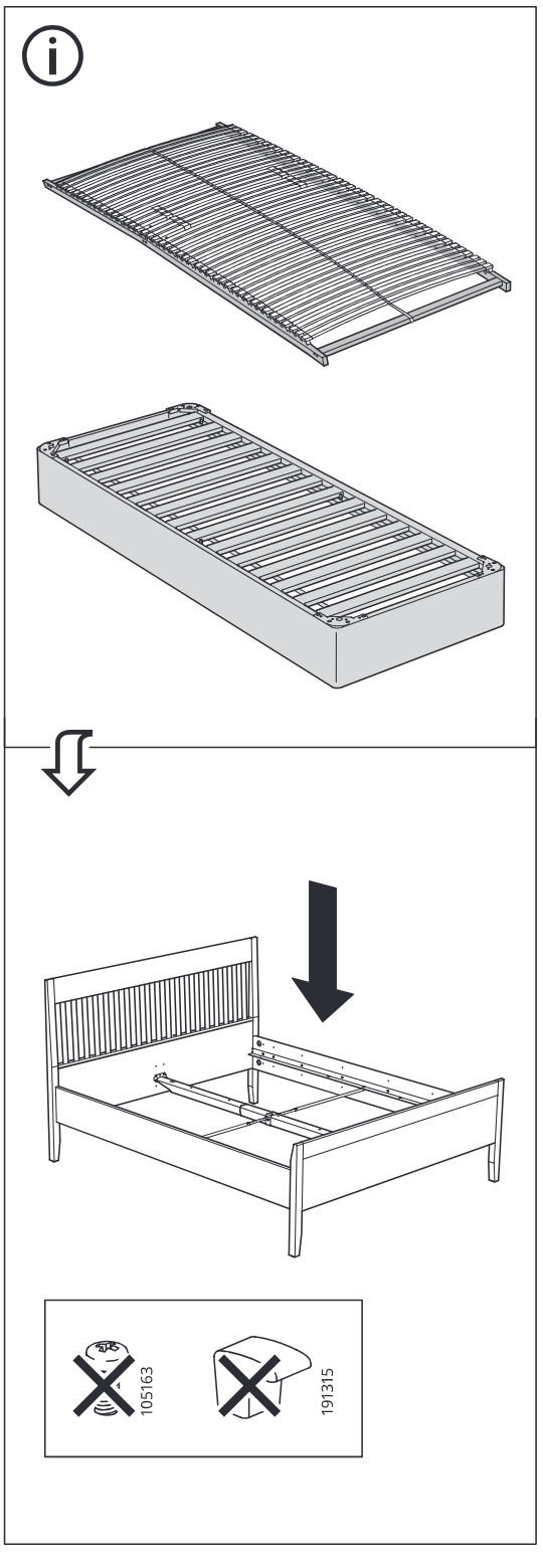
Step 25
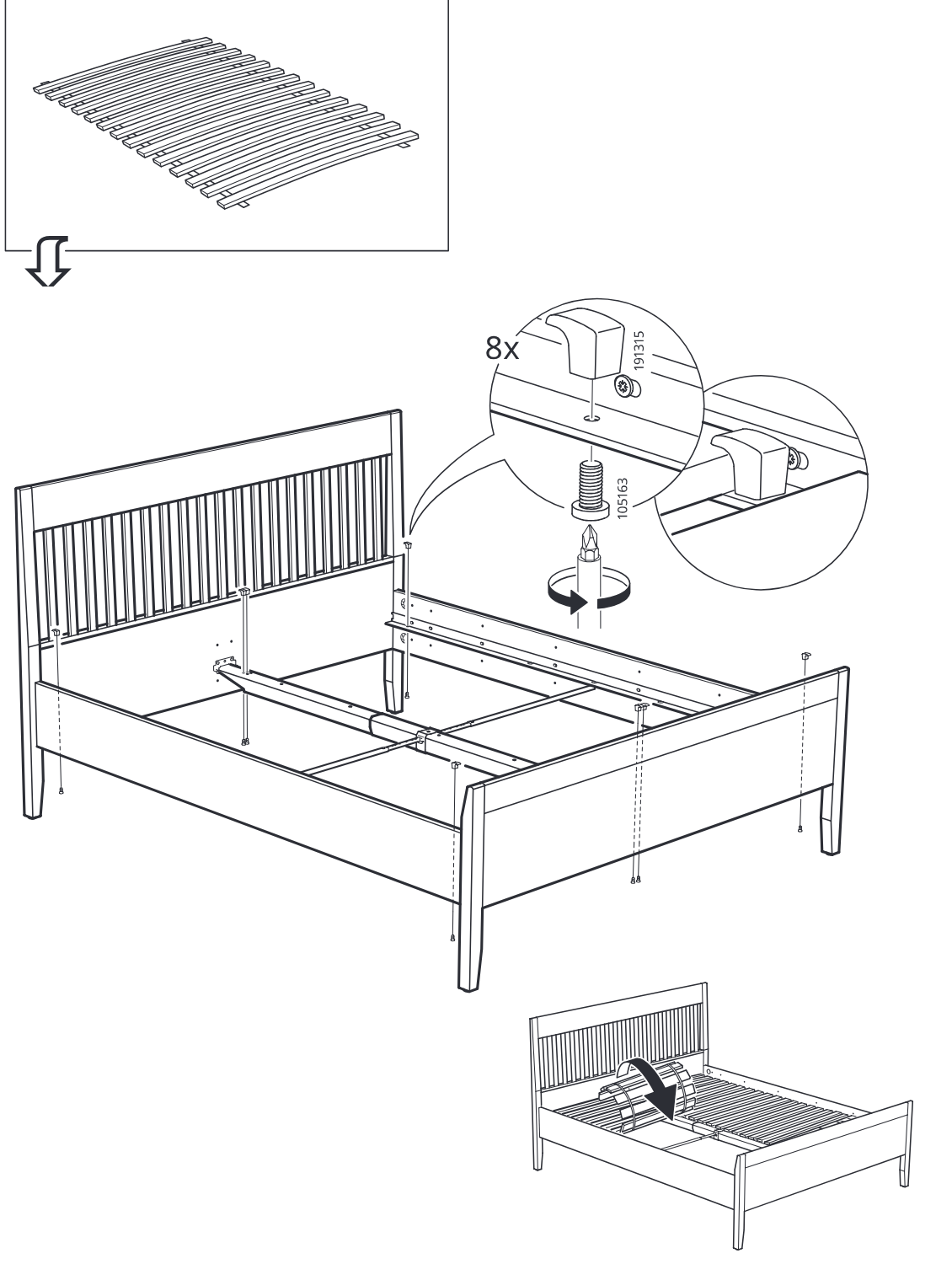
The bed frame is prepared and the slatted base section is placed into the frame, with an inline do-not-use fastener/cap note shown below.
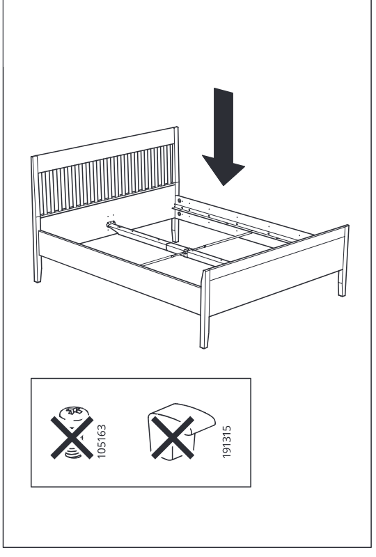
Step 26
The rolled slats are unrolled across the frame and fixed with eight clips and screws, as detailed in two zoom circles.
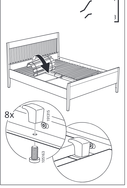
Step 27
The installer secures eight clips to the bed frame and then places the slatted base sections into the frame.