How to assemble IKEA KALLAX

Shelf unit, white, 30 1/8x57 5/8"

This guide covers the white IKEA KALLAX shelf unit, 77x147 cm, article 802.758.87. Follow the shelf assembly diagrams and available video for this rectangular variant.

View on IKEA
KALLAX

Interactive assembly guide

Step-by-Step Instructions

1 different parts, 1 boxes total — click on a package to see step-by-step assembly instructions

KALLAX Shelf unit

802.758.87

x1

16"

Width

6 1/2"

Height

59"

Length

46 lb 8 oz

Weight

Start Assembly

Written guide

Step-by-step instructions with diagrams

Follow the numbered assembly steps below, or open the interactive guide above to track progress and zoom into each diagram. This guide includes 22 illustrated steps.

KALLAX Shelf unit

  1. Safety warning

    Four stacked preparation and safety panels show required tools, that assembly should be done by two people, to read or call IKEA for help if needed, and a tip-over warning to anchor the shelving unit to the wall.
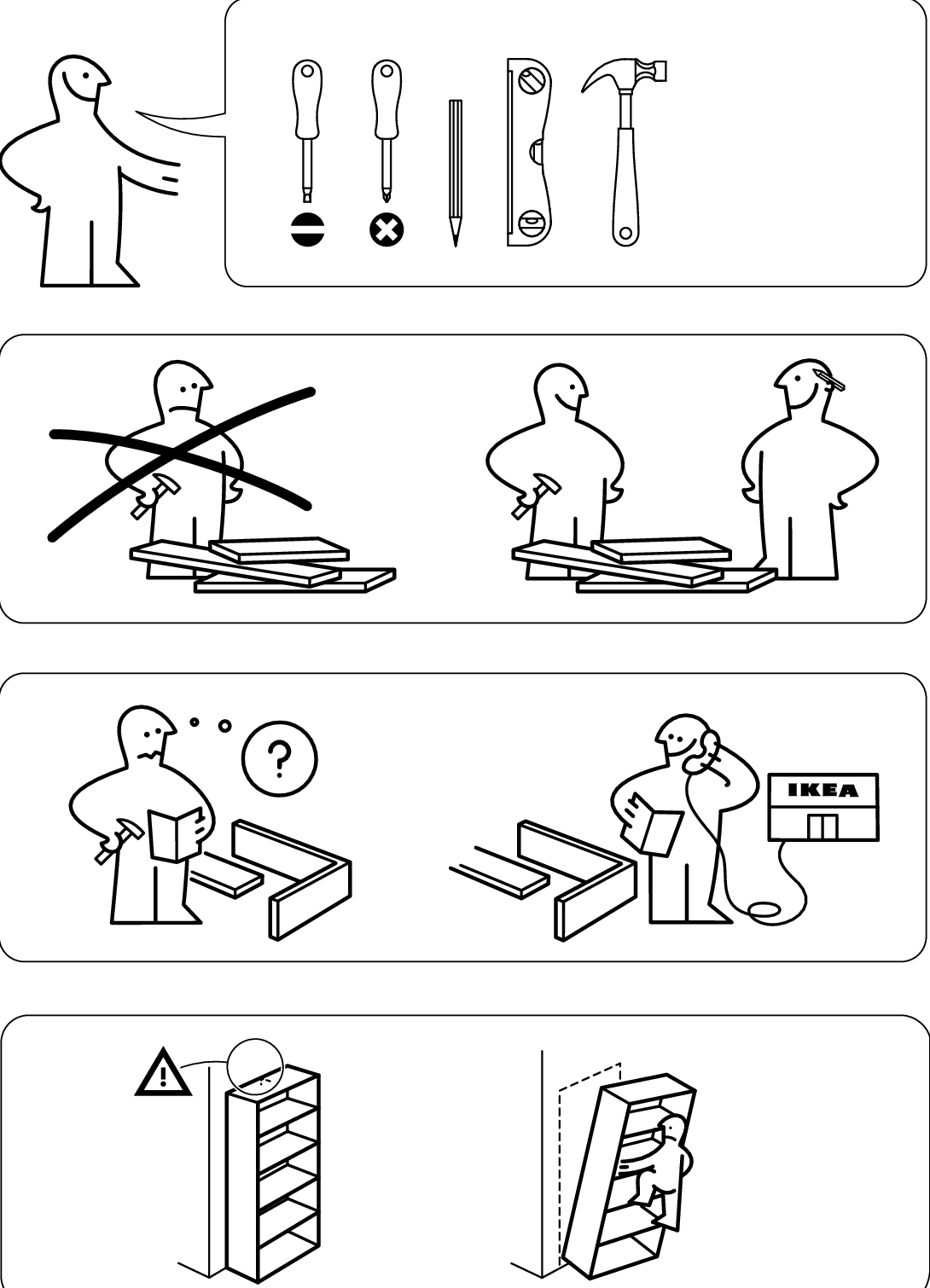
    Illustration for safety warning: Four stacked preparation and safety panels show required tools, that assembly should be done by two people, to read or call IKEA for help if needed, and a tip-over warning to anchor the shelving unit to the wall.
  2. Step 1

    Two screws are inserted into the side panels, with a support panel showing how to fit part 4 into rail 121030 using tool 100092 and a zoom inset identifying screws 104321/104322.
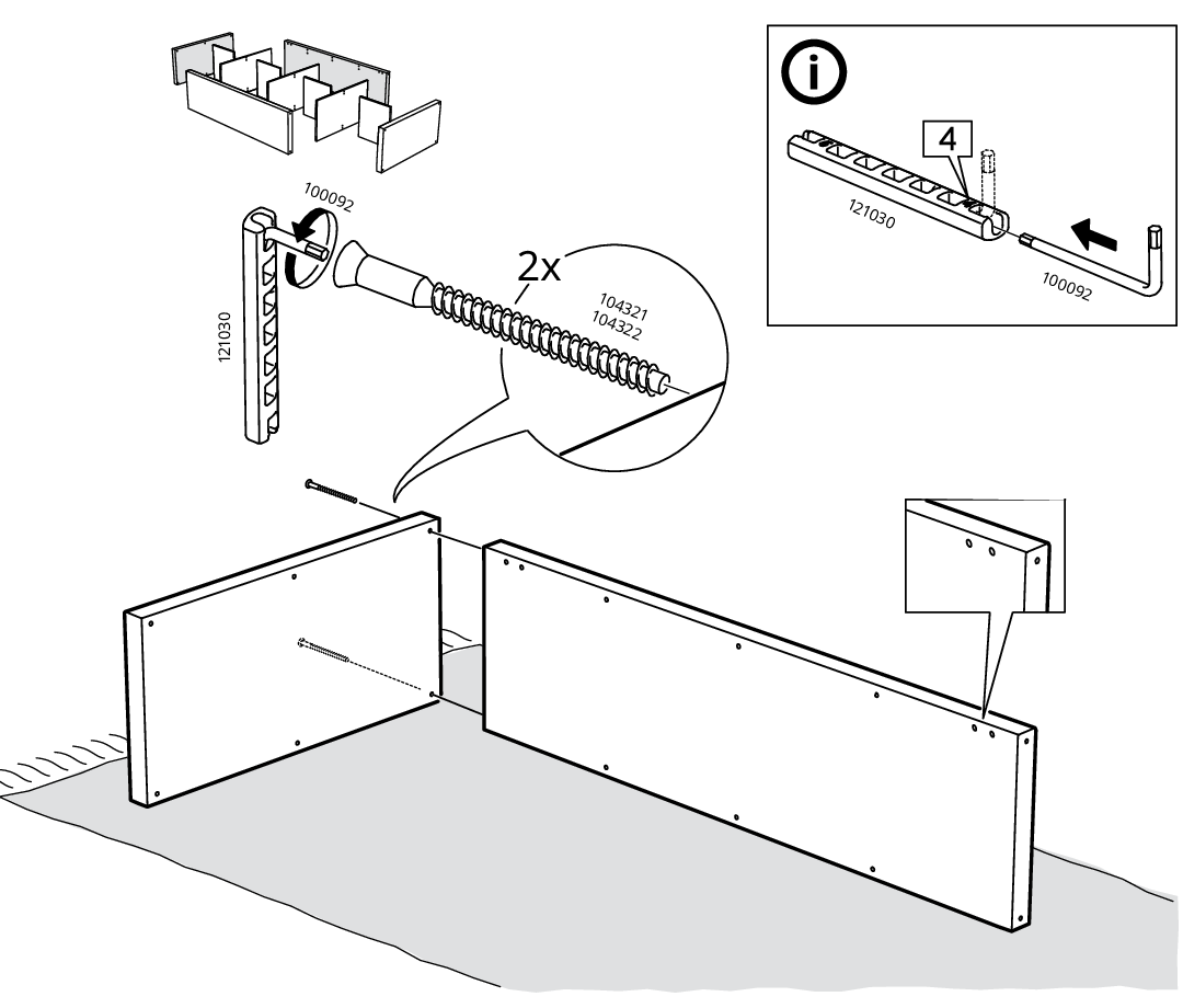
    Diagram for step 1: Two screws are inserted into the side panels, with a support panel showing how to fit part 4 into rail 121030 using tool 100092 and a zoom inset identifying screws 104321/104322.
  3. Step 2

    Two dowels 101339 are hammered into the side panels and a center divider panel is slid into place between them.
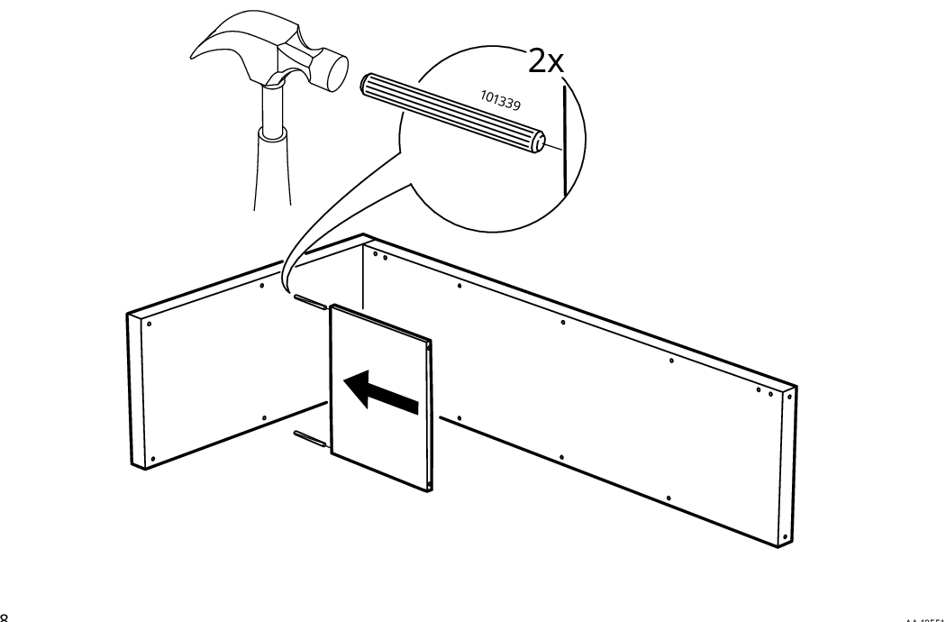
    Diagram for step 2: Two dowels 101339 are hammered into the side panels and a center divider panel is slid into place between them.
  4. Step 3

    A divider panel is slid onto two dowels between the left side and the long side panel, then two 101339 wooden dowels are tapped in with a hammer.
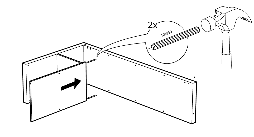
    Diagram for step 3: A divider panel is slid onto two dowels between the left side and the long side panel, then two 101339 wooden dowels are tapped in with a hammer.
  5. Step 4

    Two 101339 wooden dowels are hammered into the exposed edge holes of the installed divider panel.
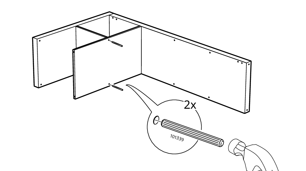
    Diagram for step 4: Two 101339 wooden dowels are hammered into the exposed edge holes of the installed divider panel.
  6. Step 5

    A second divider panel is slid leftward onto the two dowels to form the next compartment.
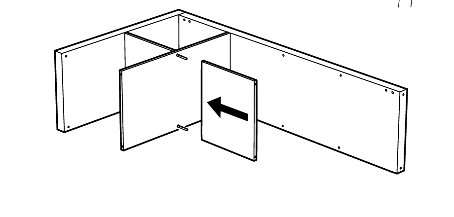
    Diagram for step 5: A second divider panel is slid leftward onto the two dowels to form the next compartment.
  7. Step 6

    The panel is slid into the frame and two wooden dowels labeled 101339 are driven in with a hammer.
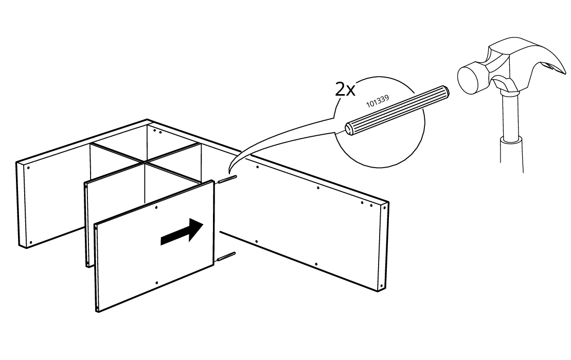
    Diagram for step 6: The panel is slid into the frame and two wooden dowels labeled 101339 are driven in with a hammer.
  8. Step 7

    A second panel is positioned in the frame and two more wooden dowels labeled 101339 are hammered into place.
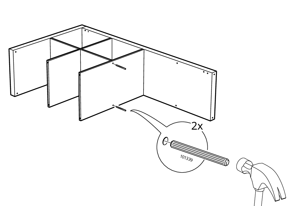
    Diagram for step 7: A second panel is positioned in the frame and two more wooden dowels labeled 101339 are hammered into place.
  9. Step 8

    A vertical divider panel slides left into the cabinet frame between the existing partitions and dowels.
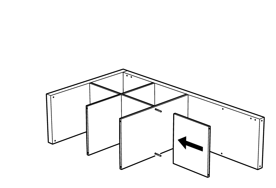
    Diagram for step 8: A vertical divider panel slides left into the cabinet frame between the existing partitions and dowels.
  10. Step 9

    A larger panel slides right into the frame and two 101339 pins are tapped in with a hammer.
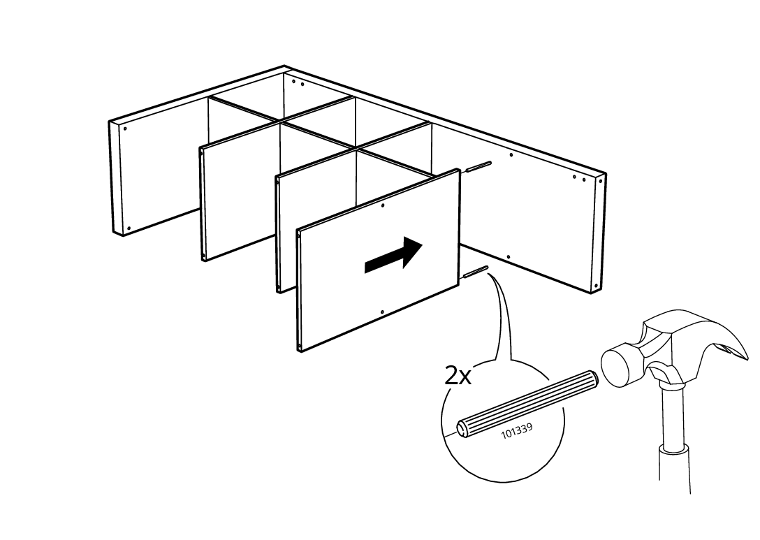
    Diagram for step 9: A larger panel slides right into the frame and two 101339 pins are tapped in with a hammer.
  11. Step 10

    Two dowels are hammered into the right side of the cabinet frame and the zoom callout shows part 101339 with a hammer, marked 2x.
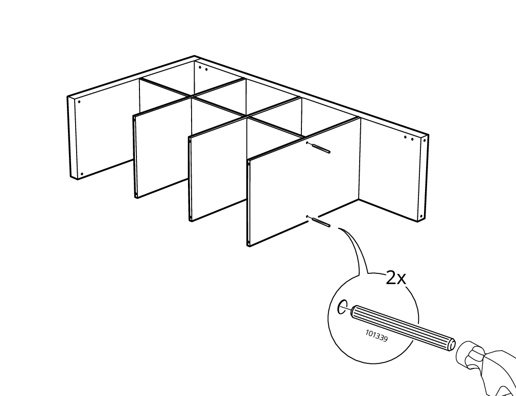
    Diagram for step 10: Two dowels are hammered into the right side of the cabinet frame and the zoom callout shows part 101339 with a hammer, marked 2x.
  12. Step 11

    A narrow panel is slid leftward onto the two exposed dowels at the right side of the cabinet frame.
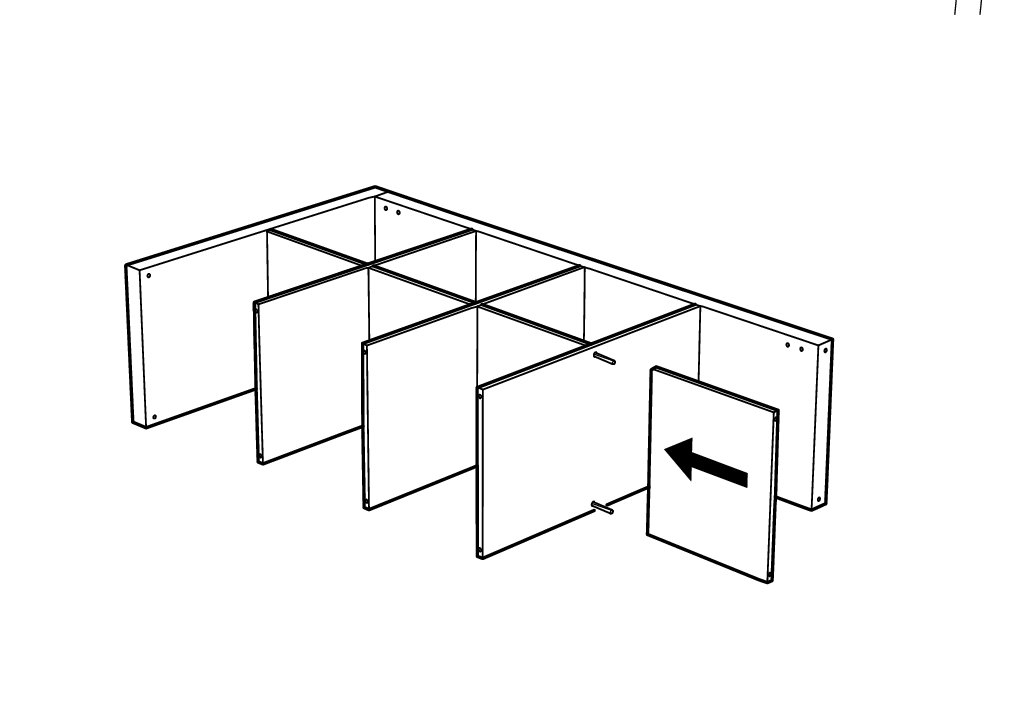
    Diagram for step 11: A narrow panel is slid leftward onto the two exposed dowels at the right side of the cabinet frame.
  13. Step 12

    The dividers are assembled between the side panels, and eight wooden dowels labeled C (101339) are hammered into the exposed side holes.
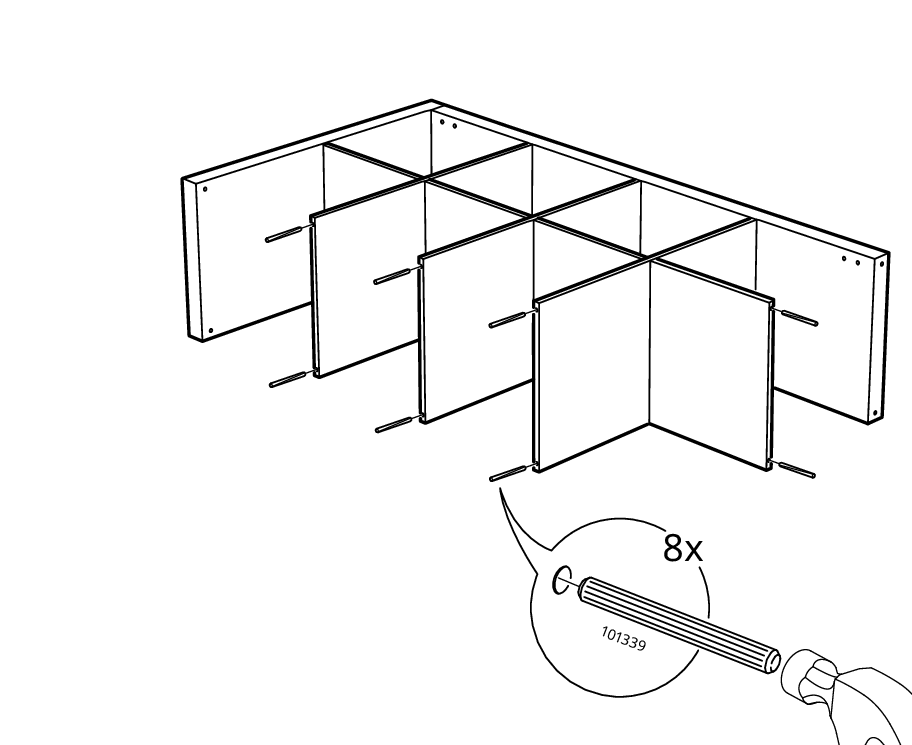
    Diagram for step 12: The dividers are assembled between the side panels, and eight wooden dowels labeled C (101339) are hammered into the exposed side holes.
  14. Step 13

    The long outer panel is aligned using the hole pattern and pushed onto the protruding dowels on the divider assembly.
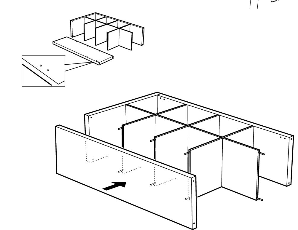
    Diagram for step 13: The long outer panel is aligned using the hole pattern and pushed onto the protruding dowels on the divider assembly.
  15. Step 14

    The side panel is attached to the storage frame with six long screws, using the slotted tool with the hex key inserted, while a free-standing info panel shows how to assemble the tool first.
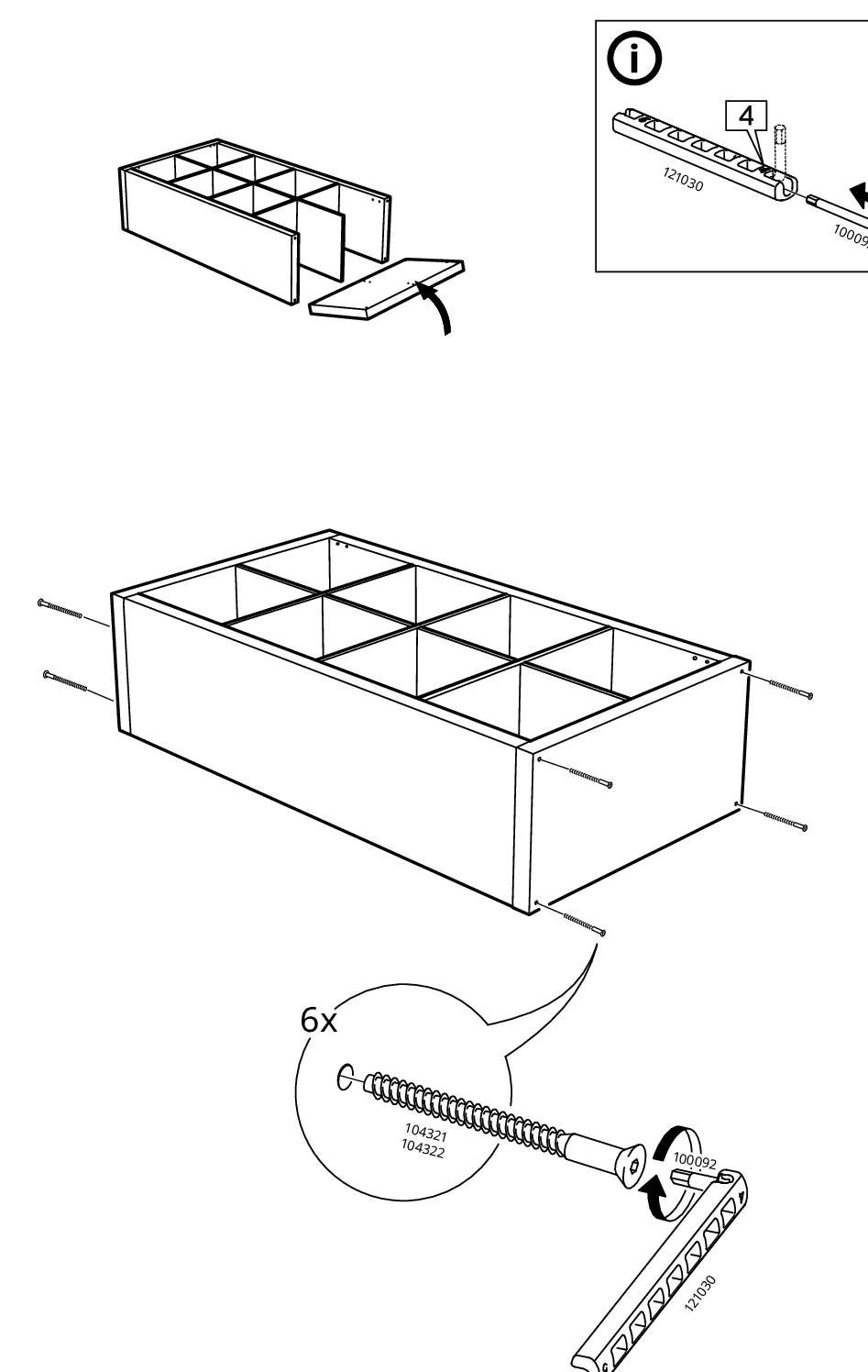
    Diagram for step 14: The side panel is attached to the storage frame with six long screws, using the slotted tool with the hex key inserted, while a free-standing info panel shows how to assemble the tool first.
  16. Before you begin

    A circled-i panel shows inserting the hex key 100092 into tool 121030 and indicates using it in position 4.
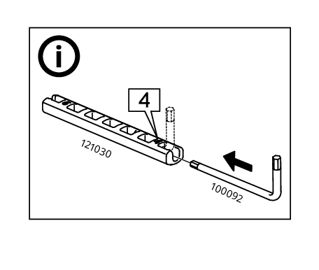
    Illustration for assembly note: A circled-i panel shows inserting the hex key 100092 into tool 121030 and indicates using it in position 4.
  17. Step 15

    The unit is laid horizontally, four adhesive floor protectors (part numbers 10002300/10050334) are applied to the side that will face down, and the page-turn icon indicates continuing to the next page.
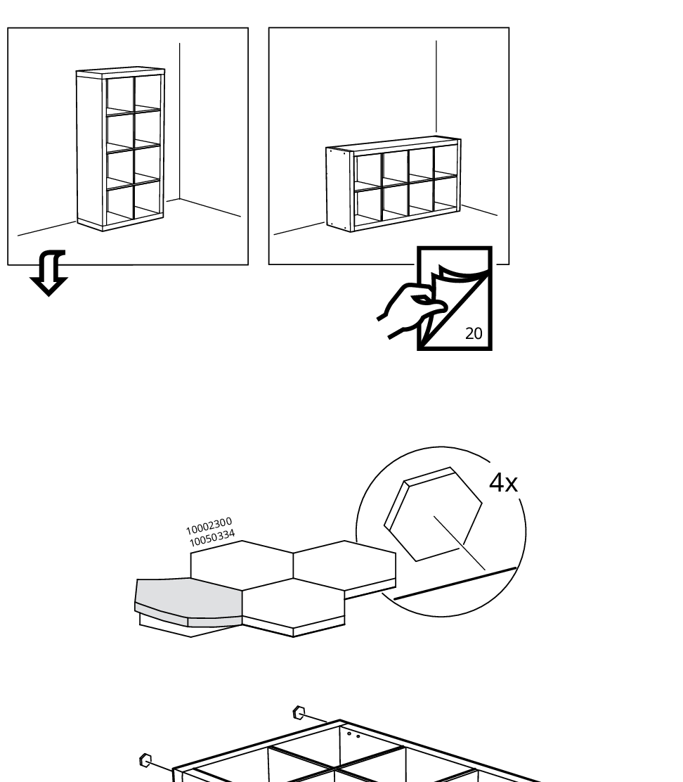
    Diagram for step 15: The unit is laid horizontally, four adhesive floor protectors (part numbers 10002300/10050334) are applied to the side that will face down, and the page-turn icon indicates continuing to the next page.
  18. Safety warning

    Safety panels show the shelving unit must be attached to the wall and must not be climbed on or used free-standing; a separate panel shows the unit crossed out when placed unsupported in a corner.
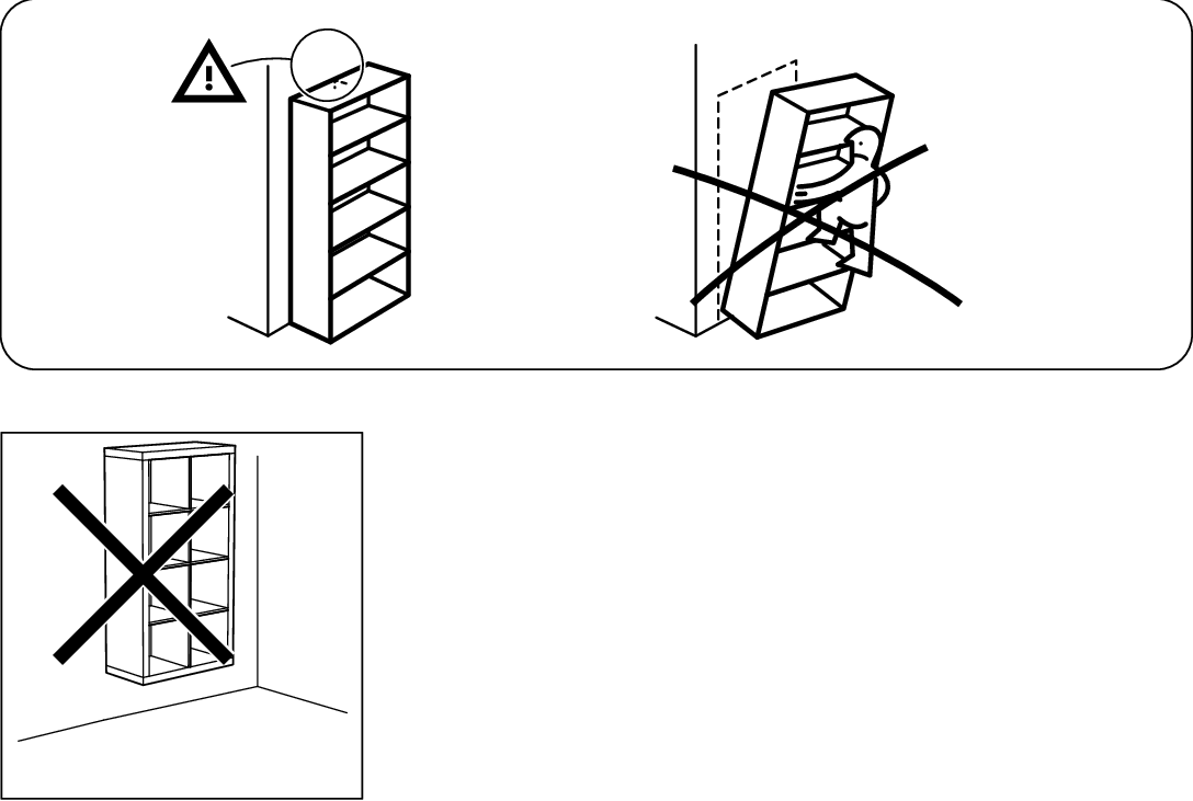
    Illustration for safety warning: Safety panels show the shelving unit must be attached to the wall and must not be climbed on or used free-standing; a separate panel shows the unit crossed out when placed unsupported in a corner.
  19. Step 16

    The cabinet is secured to the wall at the top inside corner using two screws through the wall-fixing bracket, with a zoom callout showing parts 100372 and 115753.
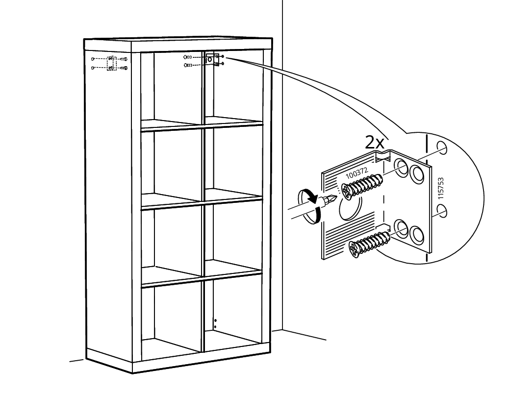
    Diagram for step 16: The cabinet is secured to the wall at the top inside corner using two screws through the wall-fixing bracket, with a zoom callout showing parts 100372 and 115753.
  20. Step 17

    The cabinet is adjusted by turning two cam fittings with a screwdriver at the top inside corner, shown with a zoomed inset and 2x label.
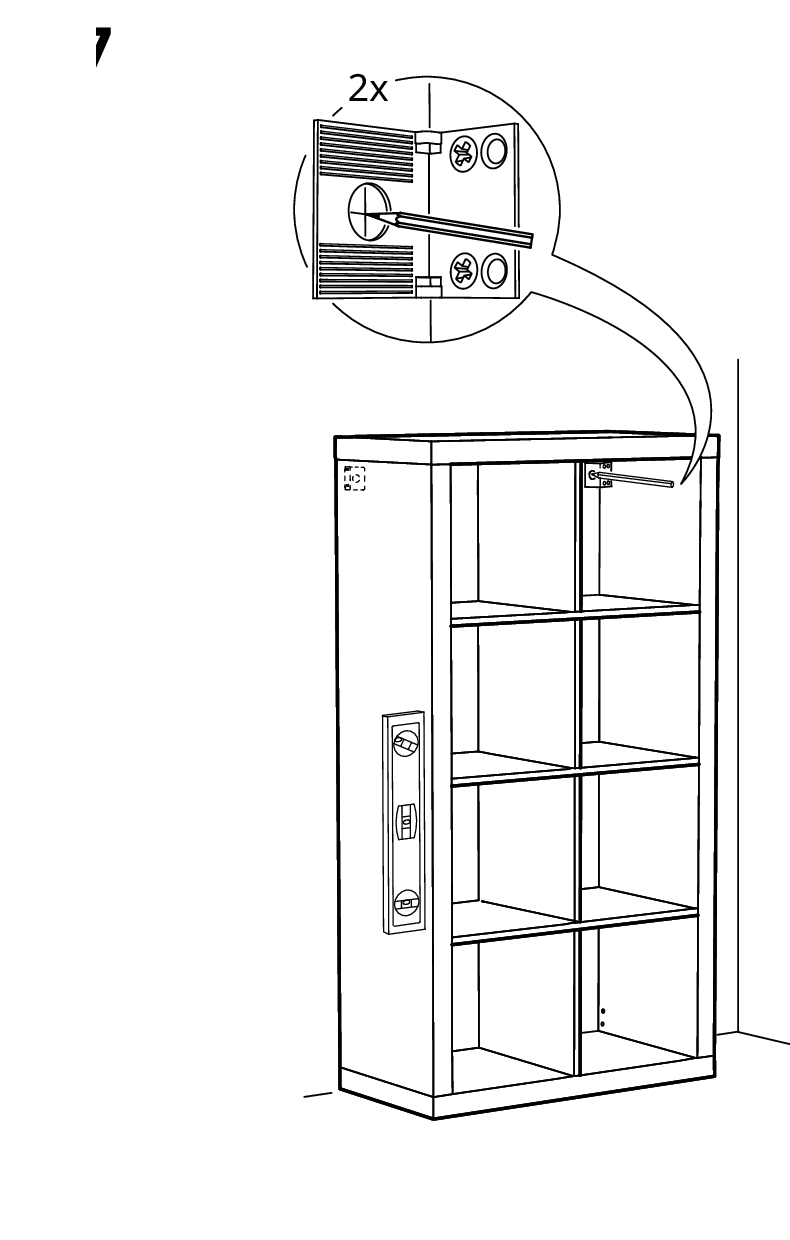
    Diagram for step 17: The cabinet is adjusted by turning two cam fittings with a screwdriver at the top inside corner, shown with a zoomed inset and 2x label.
  21. Step 18

    Two screws are fastened into the wall at the marked points, with an inline box showing the correct screw-head type and a zoom detail of the screw placement.
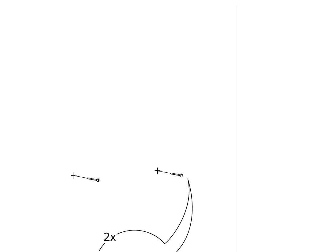
    Diagram for step 18: Two screws are fastened into the wall at the marked points, with an inline box showing the correct screw-head type and a zoom detail of the screw placement.
  22. Before you begin

    Standalone reference panel showing how to adjust and attach the wall suspension fitting: use 2x part 103693, slide and turn the bracket adjustment, then hang the cabinet on compatible rail/bracket systems 115754, 118673, 118225, 119509, 118814, and 121184.
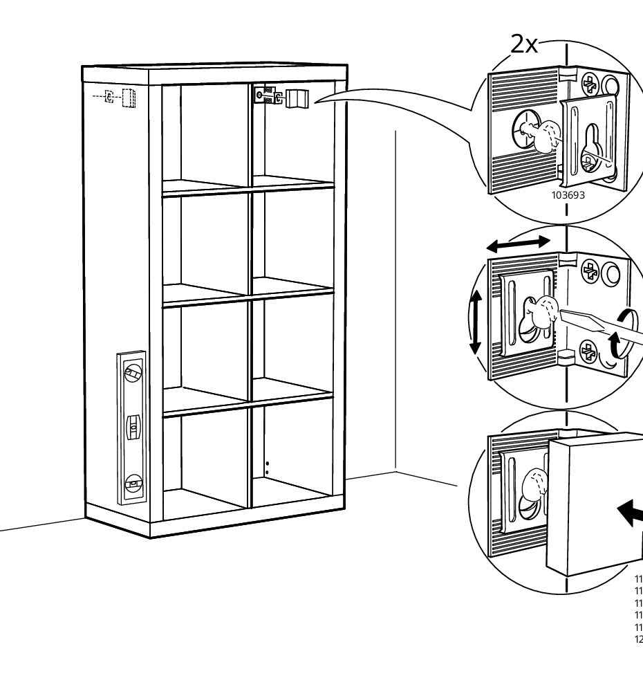
    Illustration for assembly note: Standalone reference panel showing how to adjust and attach the wall suspension fitting: use 2x part 103693, slide and turn the bracket adjustment, then hang the cabinet on compatible rail/bracket systems 115754, 118673, 118225, 119509, 118814, and 121184.
  23. Step 19

    The cabinet is laid on its back and eight feet or pads labeled 10002300/10050334 are attached to the underside while a two-person lift reminder is shown.
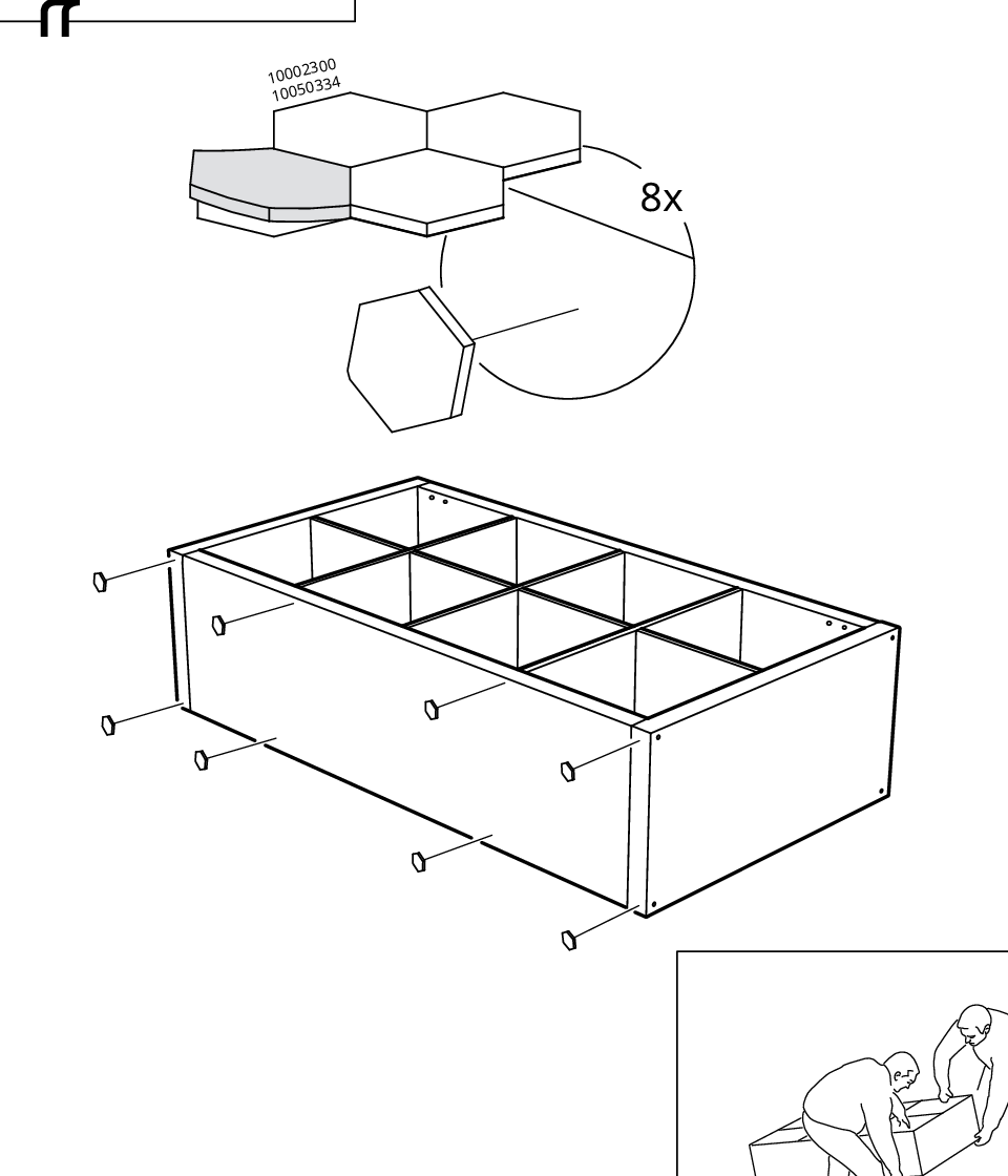
    Diagram for step 19: The cabinet is laid on its back and eight feet or pads labeled 10002300/10050334 are attached to the underside while a two-person lift reminder is shown.
  24. Safety warning

    Top safety/preparation panels show the tall unit must not be left freestanding or climbed on, and the lower panel shows the unit must not be wall-mounted sideways/horizontally.
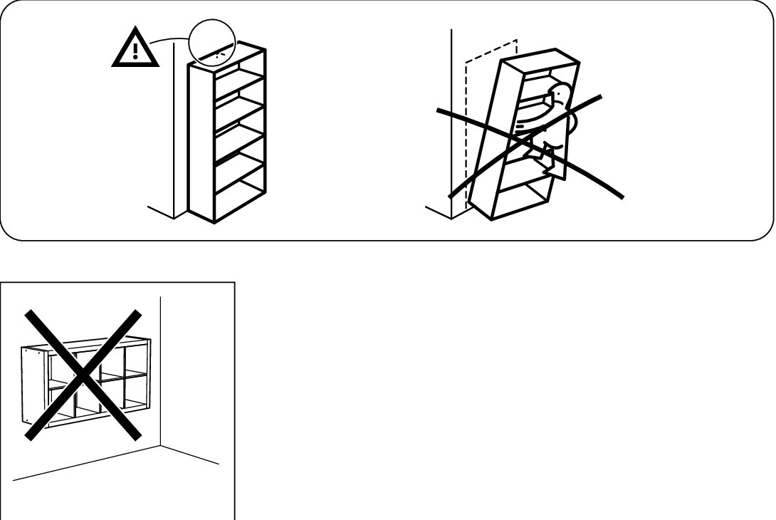
    Illustration for safety warning: Top safety/preparation panels show the tall unit must not be left freestanding or climbed on, and the lower panel shows the unit must not be wall-mounted sideways/horizontally.
  25. Step 20

    The cabinet is laid on its back and a wall-fixing bracket is attached inside the upper corner with 2 screws and tightened with a screwdriver.
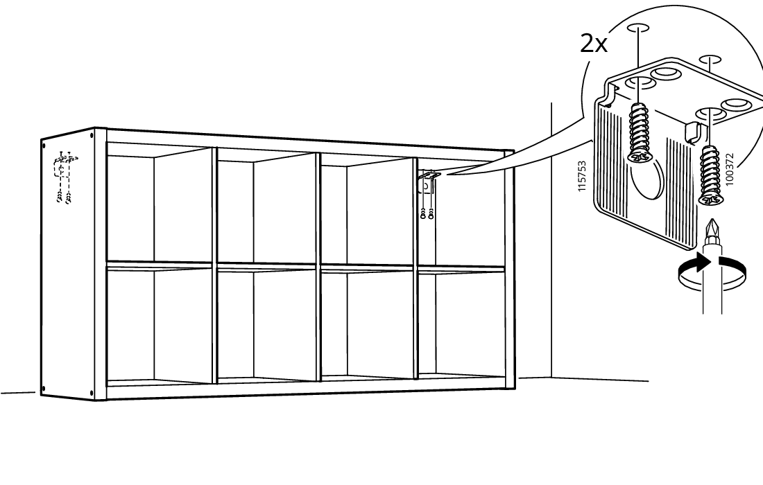
    Diagram for step 20: The cabinet is laid on its back and a wall-fixing bracket is attached inside the upper corner with 2 screws and tightened with a screwdriver.
  26. Step 21

    Two wall fasteners 115753 are screwed into the cabinet side panels through the interior near the top to secure the unit against the wall.
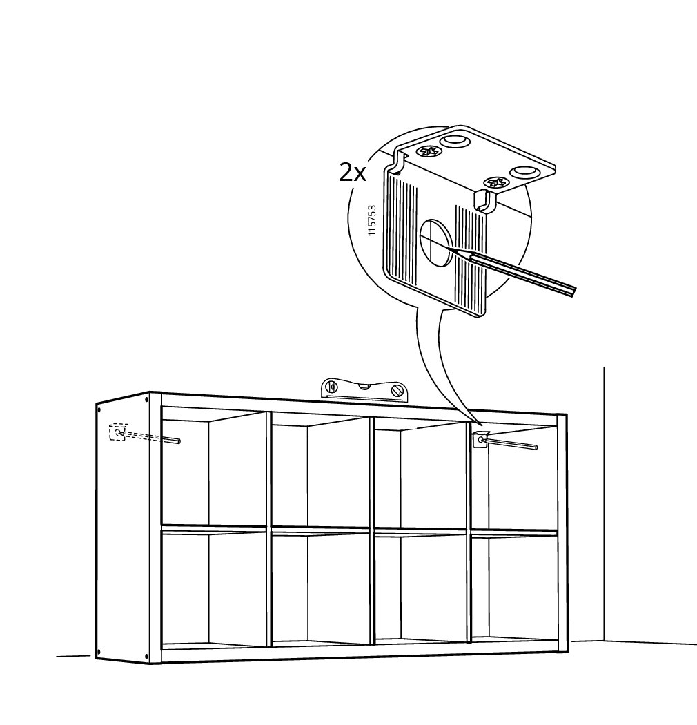
    Diagram for step 21: Two wall fasteners 115753 are screwed into the cabinet side panels through the interior near the top to secure the unit against the wall.
  27. Step 22

    Two screws are installed into the wall at marked points, with a zoom callout showing the screw detail and an inset indicating the correct wall plug orientation.
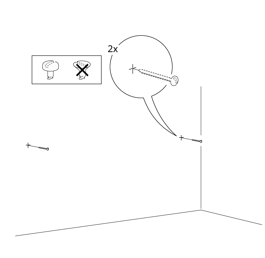
    Diagram for step 22: Two screws are installed into the wall at marked points, with a zoom callout showing the screw detail and an inset indicating the correct wall plug orientation.
  28. Before you begin

    Adjustment panel shows installing two suspension brackets (115753 and 103693), then loosening/turning the cam to adjust the cabinet up/down and side-to-side before sliding the cabinet onto the wall rail; applies to article numbers 115754, 118673, 118225, 119509, 118814, and 121184.
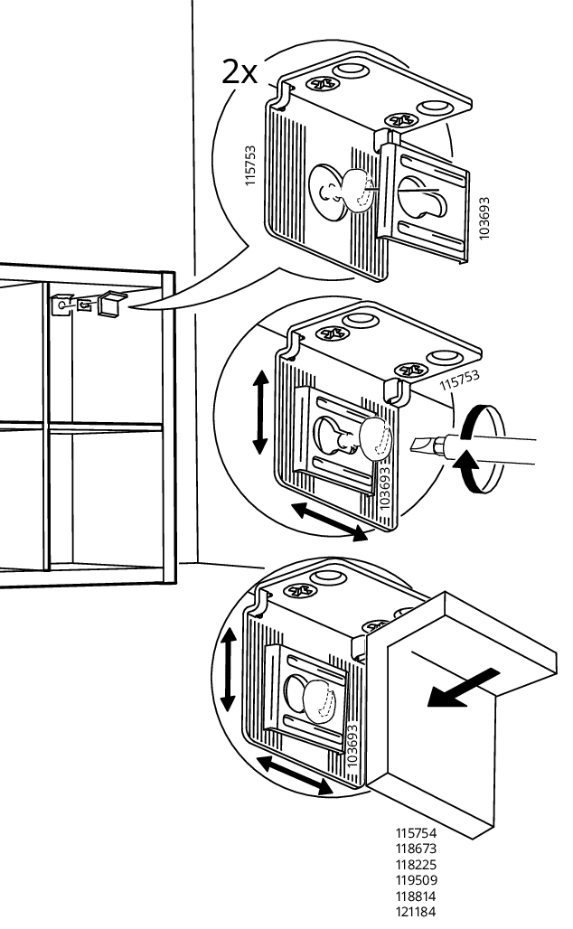
    Illustration for assembly note: Adjustment panel shows installing two suspension brackets (115753 and 103693), then loosening/turning the cam to adjust the cabinet up/down and side-to-side before sliding the cabinet onto the wall rail; applies to article numbers 115754, 118673, 118225, 119509, 118814, and 121184.

Make it yours

Small additions. A better setup.

These optional additions are separate from any parts, safety equipment, or tools required to assemble the product.

Explore finishing touches

Some links are affiliate links. We may earn a commission if you buy through them, at no extra cost to you. As an Amazon Associate, we earn from qualifying purchases.

  • Amazon Basics fabric storage cubes, beige (6-pack)

    Soft cubes add removable storage to open KALLAX compartments.

    Each cube is 10.5 × 10.5 × 11 in (26.7 × 26.7 × 27.9 cm), smaller than the 33 × 33 × 39 cm KALLAX opening. Seams, handles, or inserts can reduce clearance; do not force a cube.

    View product
  • Officemate weighted bookends, black (pair)

    A padded, freestanding bookend keeps a short row of books upright in a KALLAX cubby.

    Use one bookend per cubby, with the cubby wall supporting the other end; the pair can serve two cubbies. Do not put both bases side by side in one cubby. Keep total shelf load within IKEA’s 13 kg limit.

    Image reuse rights have not been independently verified.

    View product
  • Simple Houseware magazine files, white (6-pack)

    Upright files keep magazines and light papers tidy in a KALLAX cubby.

    Each file is 24.77 × 9.53 × 31.12 cm; the KALLAX opening is 33 × 33 × 39 cm. Three span about 28.6 cm, with under 2 cm height clearance. Check the assembled fit, use for light papers only, and do not force them.

    Image reuse rights have not been independently verified.

    View product
  • Amazon Basics freestanding cabinet shelf, white (2-pack)

    A small freestanding shelf adds a second level inside a KALLAX cubby.

    Each 31.75 × 20.32 × 11.43 cm shelf fits within a 33 × 33 × 39 cm cubby. Use for lightweight items only; the listing gives no shelf load rating, and total KALLAX load must stay within 13 kg.

    Image reuse rights have not been independently verified.

    View product

Built it. Now make it yours.

Explore creative ways to personalize your KALLAX. Project details include creator sources and measurement or material notes to check before starting.

  • Video thumbnail: DIY IKEA HACK KALLAX TRANSFORMATION | FLUTED SIDEBOARD by Kristen McGowan
    customize

    Fluted Sideboard-Style KALLAX Transformation

    Video by Kristen McGowan ·

    Transforms a boxy KALLAX unit into a custom-looking fluted sideboard while retaining storage space and creating solid-looking cabinet doors.

    Explore this hack

Video guide

Dimensions

Width

30 1/8"

Depth

15 3/8"

Height

57 5/8"

Product dimensions