How to assemble IKEA KALLAX Shelf unit

KALLAX Shelf unit, white, 57 7/8x57 7/8"

This guide covers the white IKEA KALLAX shelf unit, 147x147 cm, article 302.758.61. Use the illustrated instructions and video for this square shelving unit.

View on IKEA
KALLAX Shelf unit

Interactive assembly guide

Step-by-Step Instructions

1 different parts, 1 boxes total — click on a package to see step-by-step assembly instructions

KALLAX Shelf unit

302.758.61

x1

15 ¾ "

Width

6 ¼ "

Height

59 ½ "

Length

39 lb 11 oz

Weight

Start Assembly

Written guide

Step-by-step instructions with diagrams

Follow the numbered assembly steps below, or open the interactive guide above to track progress and zoom into each diagram. This guide includes 26 illustrated steps.

KALLAX Shelf unit

  1. Step 1

    The assembler prepares tool 121030 with insert 4 and hex key 100092, then drives two screws 104327/104322 to join two long boards at a right angle.
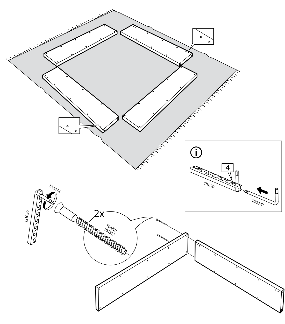
    Diagram for step 1: The assembler prepares tool 121030 with insert 4 and hex key 100092, then drives two screws 104327/104322 to join two long boards at a right angle.
  2. Step 2

    Hammer six dowels 101339 into the side holes of the three small panels, two dowels per panel, as shown in the magnified detail.
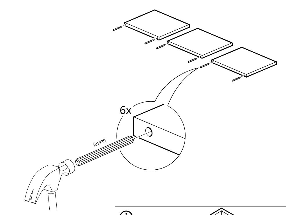
    Diagram for step 2: Hammer six dowels 101339 into the side holes of the three small panels, two dowels per panel, as shown in the magnified detail.
  3. Before you begin

    Orientation panel shows the three inner panels must all face the same direction with arrows pointing left and marks the opposite arrangement as incorrect.
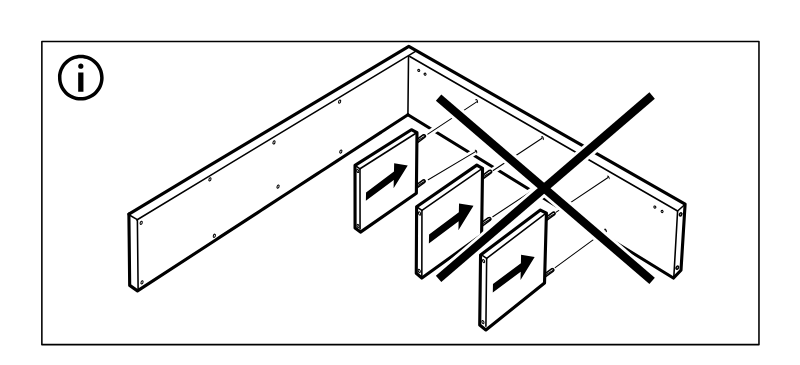
    Illustration for assembly note: Orientation panel shows the three inner panels must all face the same direction with arrows pointing left and marks the opposite arrangement as incorrect.
  4. Step 3

    Insert the three small panels with left-pointing arrow faces into the matching slots between the two long side panels.
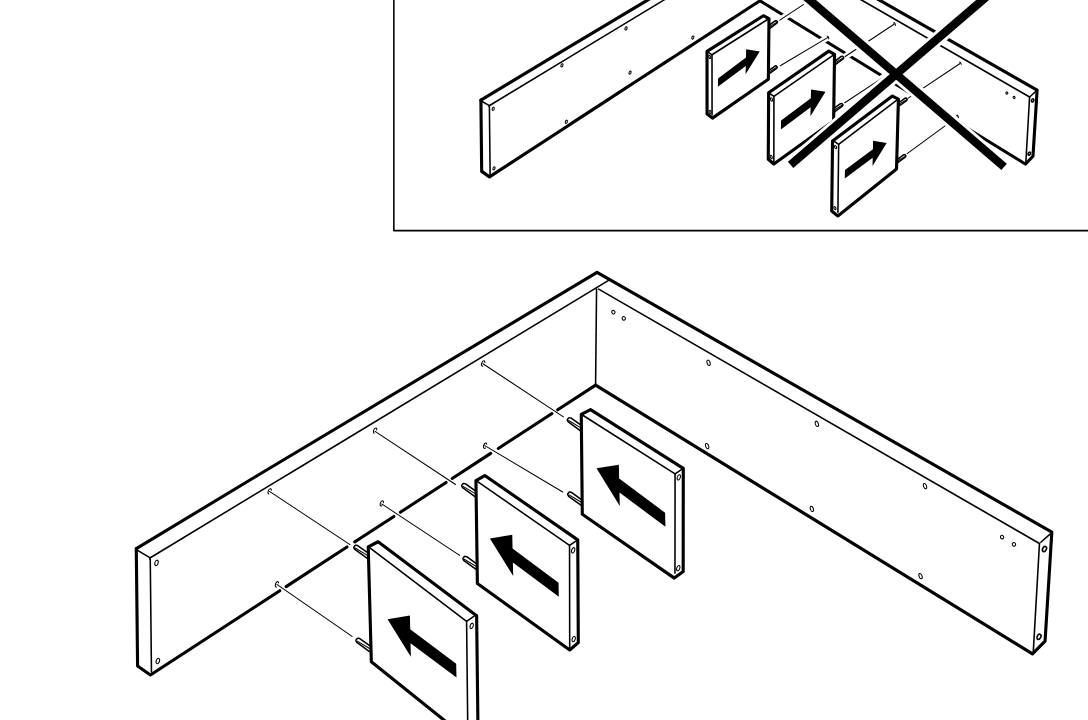
    Diagram for step 3: Insert the three small panels with left-pointing arrow faces into the matching slots between the two long side panels.
  5. Step 4

    Twelve dowels C labeled 101339 are hammered into the ends of three long boards, as shown in the zoom detail.
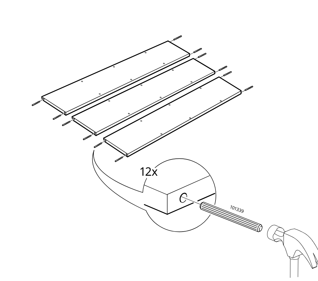
    Diagram for step 4: Twelve dowels C labeled 101339 are hammered into the ends of three long boards, as shown in the zoom detail.
  6. Step 5

    The long panel with dowels is inserted into the side of the partially assembled frame in the direction of the arrow.
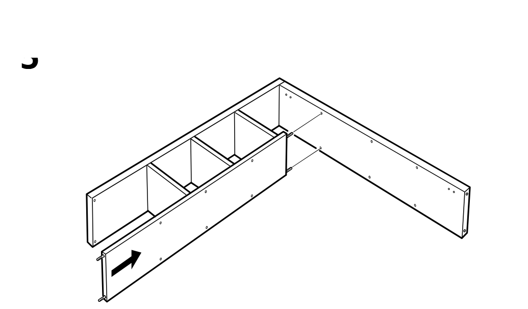
    Diagram for step 5: The long panel with dowels is inserted into the side of the partially assembled frame in the direction of the arrow.
  7. Step 6

    Hammer six wooden dowels into the indicated holes in the cabinet frame.
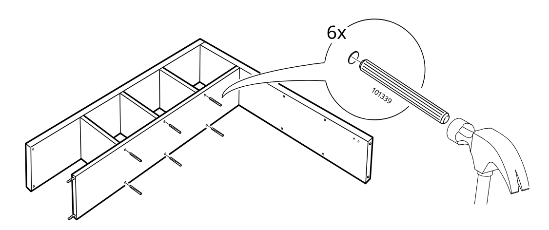
    Diagram for step 6: Hammer six wooden dowels into the indicated holes in the cabinet frame.
  8. Step 7

    Slide the three inner divider panels onto the exposed dowels in the frame.
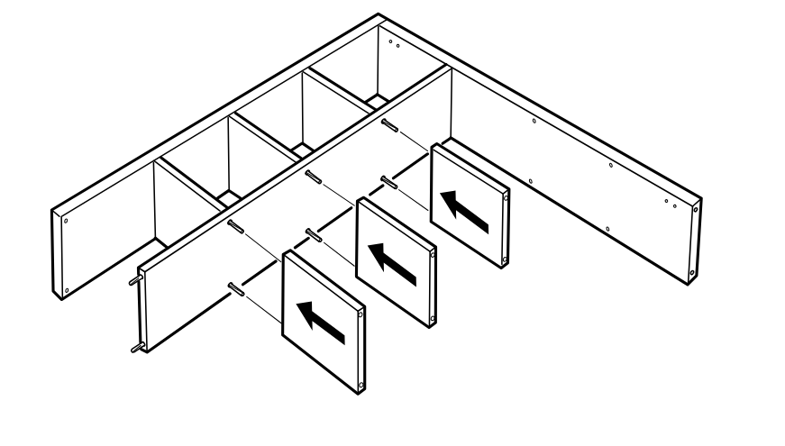
    Diagram for step 7: Slide the three inner divider panels onto the exposed dowels in the frame.
  9. Step 8

    Push the long front panel into place onto the protruding fittings at the front of the unit.
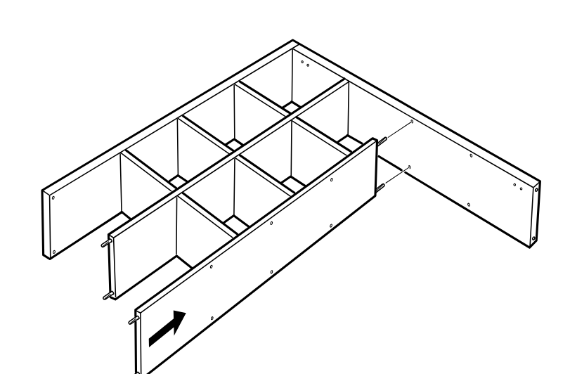
    Diagram for step 8: Push the long front panel into place onto the protruding fittings at the front of the unit.
  10. Step 9

    Six dowels are hammered into the side holes of the three inner panels, shown with a zoom callout of part 101339 and a hammer.
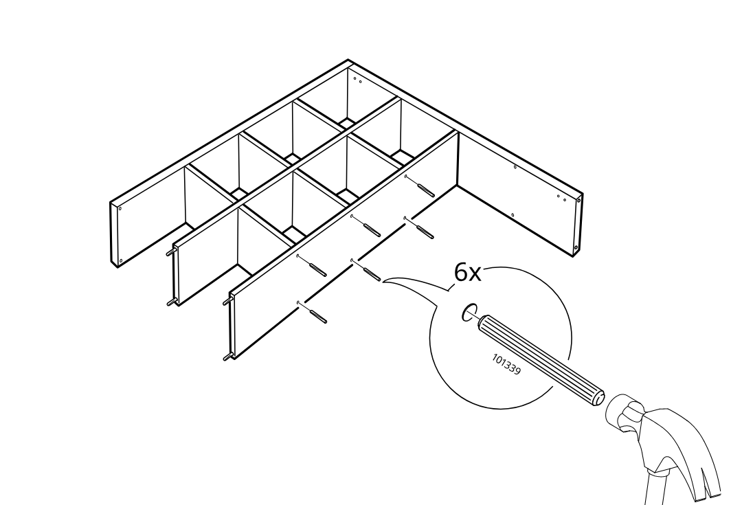
    Diagram for step 9: Six dowels are hammered into the side holes of the three inner panels, shown with a zoom callout of part 101339 and a hammer.
  11. Step 10

    Three small panels are pushed onto the protruding dowels between the inner dividers, sliding inward as indicated by the arrows.
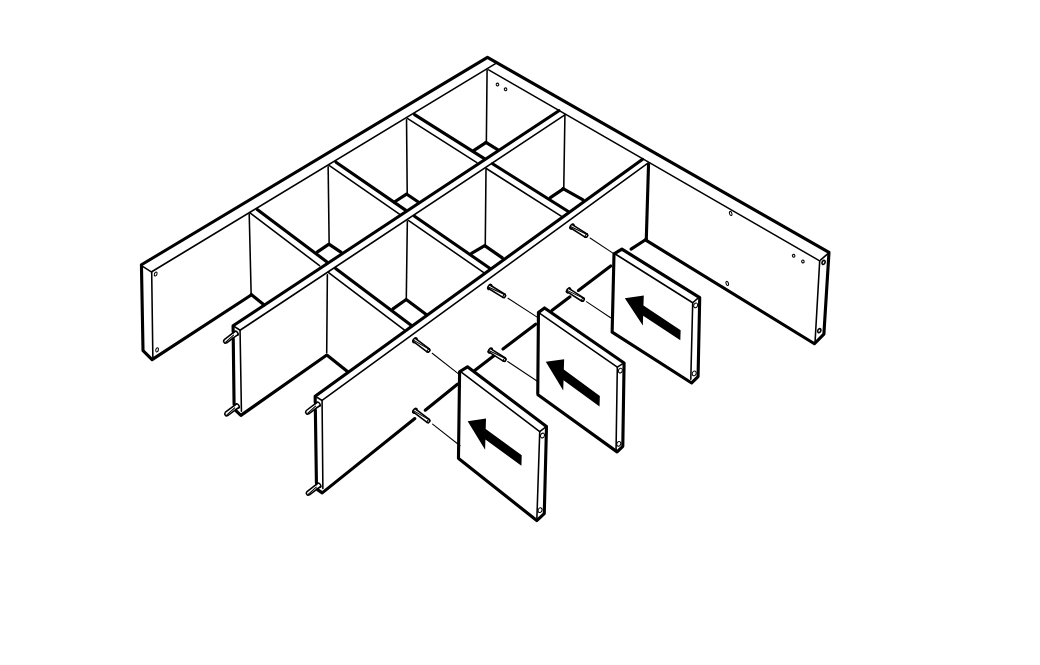
    Diagram for step 10: Three small panels are pushed onto the protruding dowels between the inner dividers, sliding inward as indicated by the arrows.
  12. Step 11

    The long side panel is aligned and slid onto the exposed ends of the internal dividers and top panel assembly.
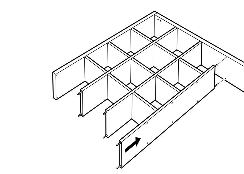
    Diagram for step 11: The long side panel is aligned and slid onto the exposed ends of the internal dividers and top panel assembly.
  13. Step 12

    Six dowels labeled 101339 are inserted into the side panel holes, with a hammer shown for tapping them into place.
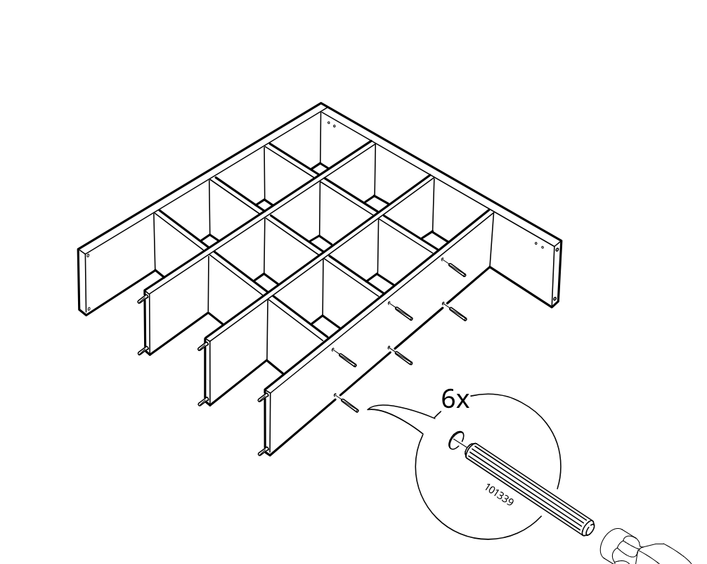
    Diagram for step 12: Six dowels labeled 101339 are inserted into the side panel holes, with a hammer shown for tapping them into place.
  14. Step 13

    Three divider panels are slid leftward onto the exposed connectors on the side of the assembled grid.
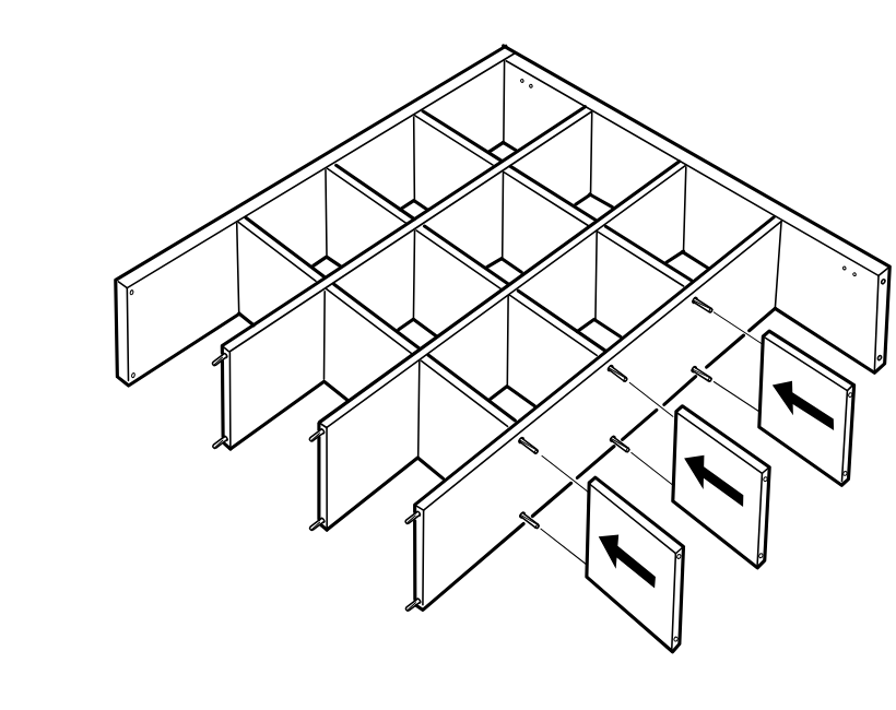
    Diagram for step 13: Three divider panels are slid leftward onto the exposed connectors on the side of the assembled grid.
  15. Step 14

    The grid assembly is positioned on the long panel with the hole pattern aligned as shown, and the large side board is rotated upward into place around the structure.
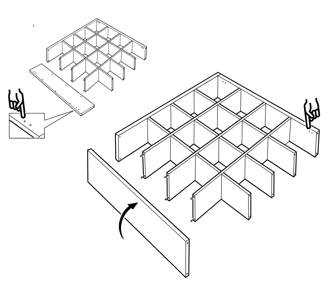
    Diagram for step 14: The grid assembly is positioned on the long panel with the hole pattern aligned as shown, and the large side board is rotated upward into place around the structure.
  16. Step 15

    Prepare rail 121030 with insert 100092 as shown in the inset, then fasten the cabinet frame with two screws 104321/104322 into the left side panel.
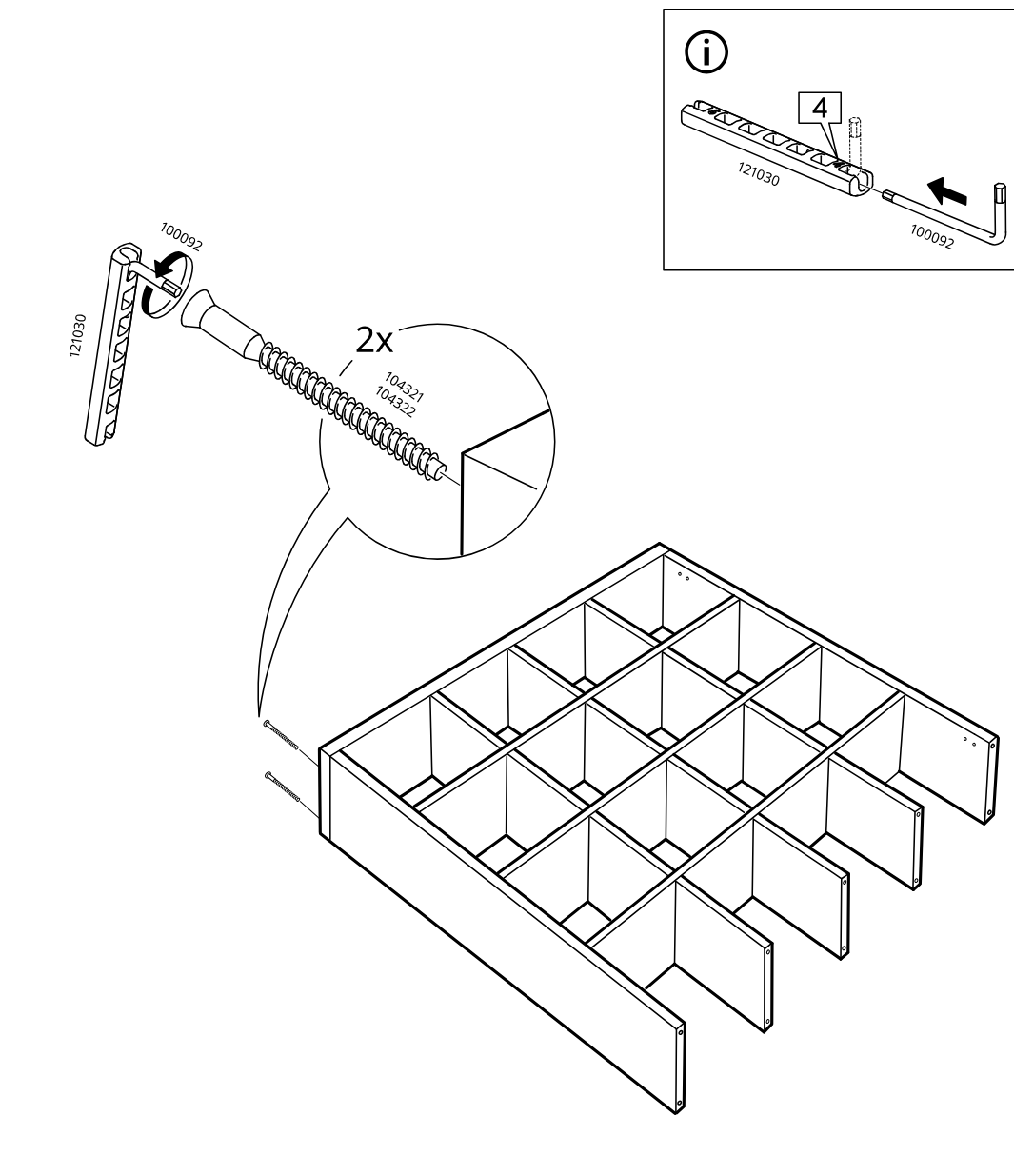
    Diagram for step 15: Prepare rail 121030 with insert 100092 as shown in the inset, then fasten the cabinet frame with two screws 104321/104322 into the left side panel.
  17. Step 16

    Hammer six 101339 dowels into the holes on the three inner divider panels of the cabinet frame.
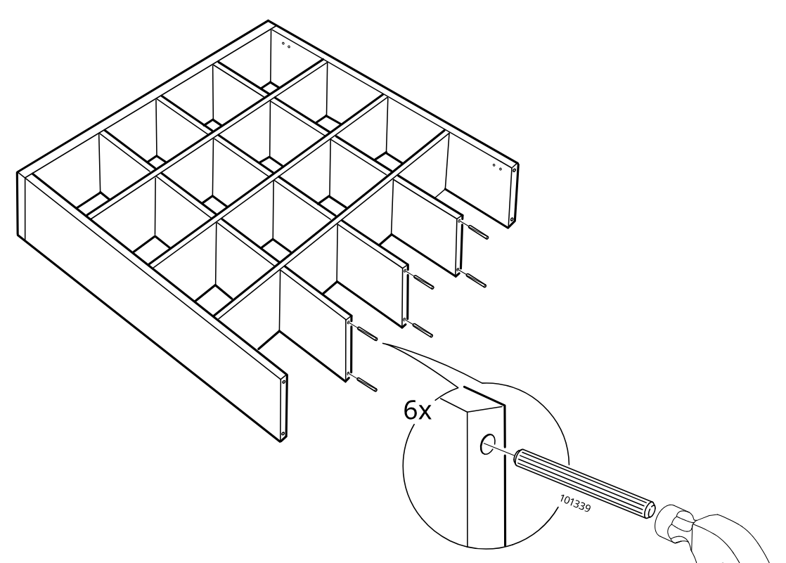
    Diagram for step 16: Hammer six 101339 dowels into the holes on the three inner divider panels of the cabinet frame.
  18. Step 17

    Fit the long side panel onto the exposed dowels on the open side of the cabinet assembly.
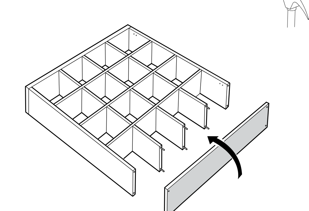
    Diagram for step 17: Fit the long side panel onto the exposed dowels on the open side of the cabinet assembly.
  19. Step 18

    The side panel is fastened with four screw assemblies, and the slotted part 121030 is turned with tool 100092 as shown in the connected info inset.
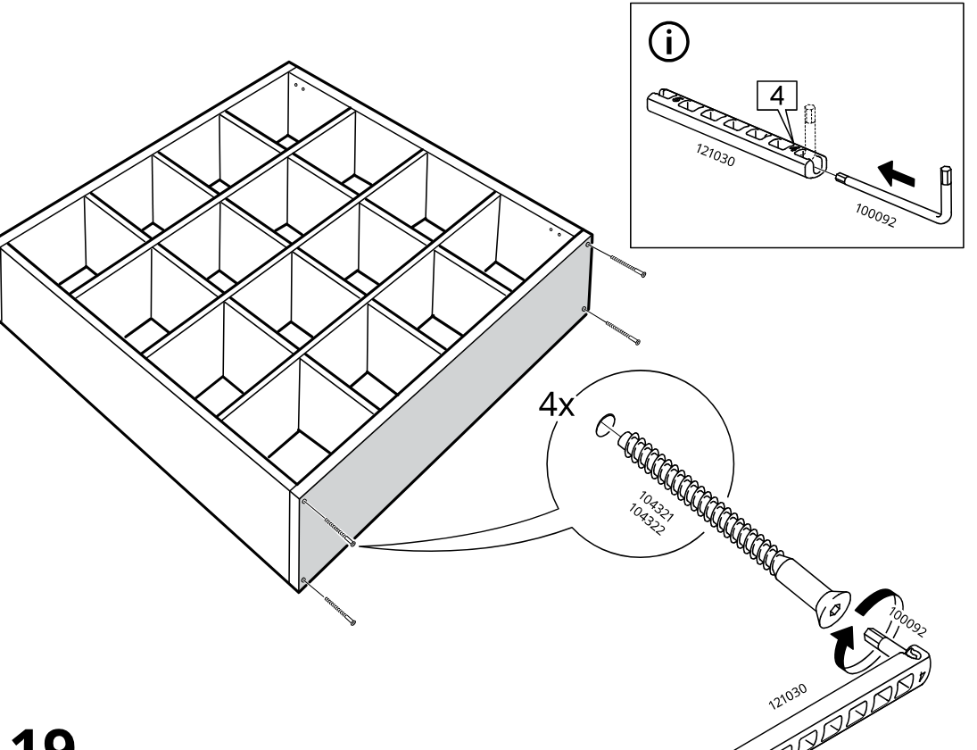
    Diagram for step 18: The side panel is fastened with four screw assemblies, and the slotted part 121030 is turned with tool 100092 as shown in the connected info inset.
  20. Step 19

    Ten hexagonal caps are inserted into the exposed side holes along the panel.
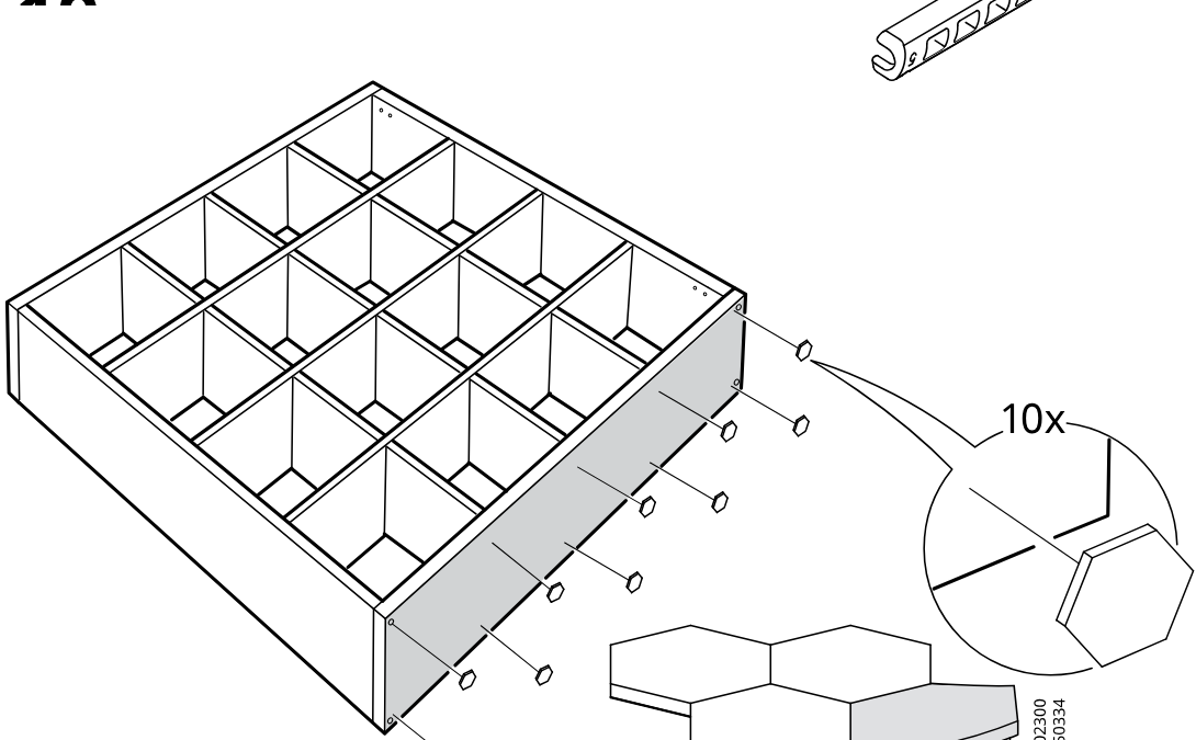
    Diagram for step 19: Ten hexagonal caps are inserted into the exposed side holes along the panel.
  21. Step 20

    The unit is moved upright, positioned away from side-wall placement, leveled vertically, and secured with two 100372 screws into fitting 115753 as shown in the zoom detail.
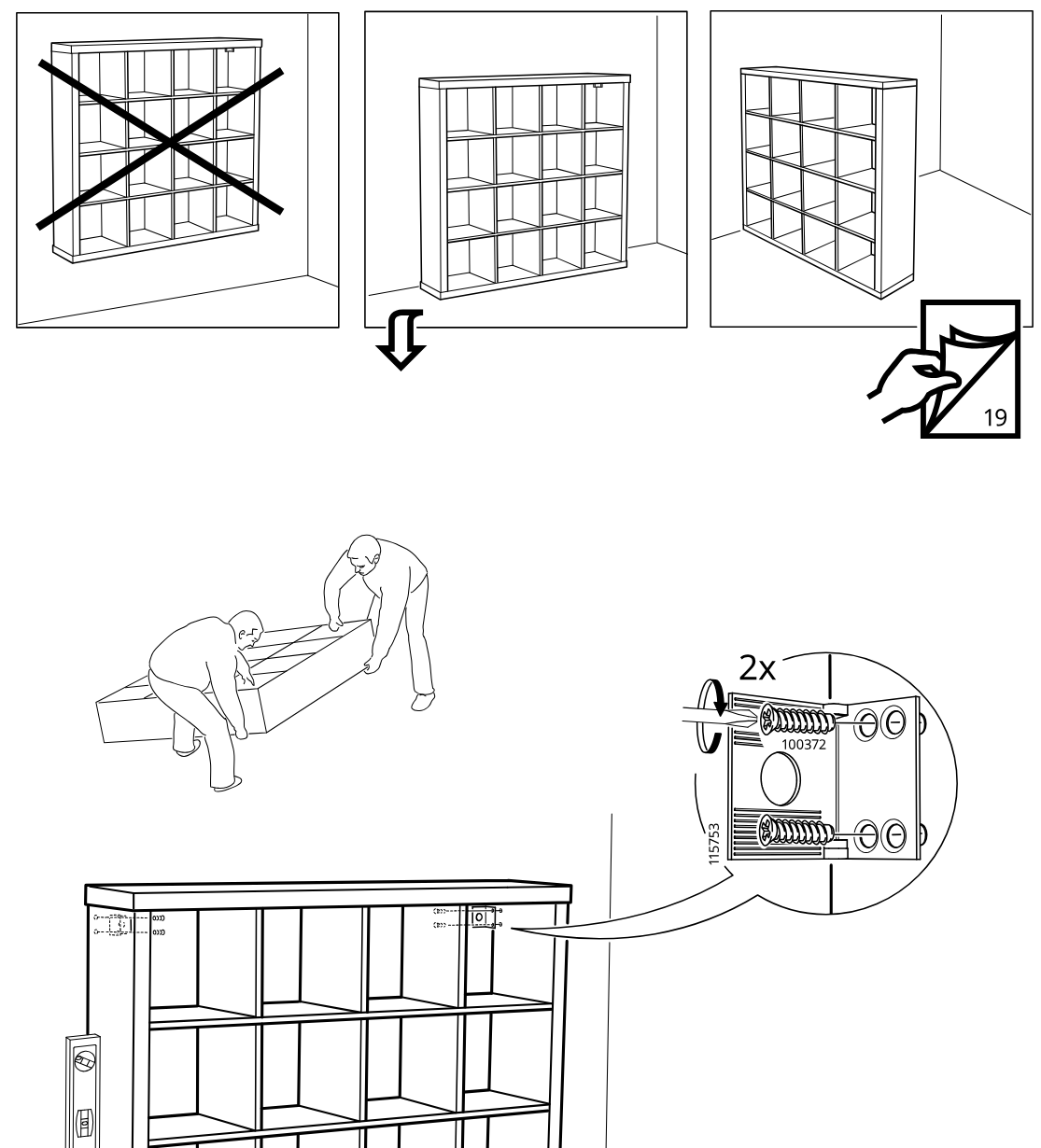
    Diagram for step 20: The unit is moved upright, positioned away from side-wall placement, leveled vertically, and secured with two 100372 screws into fitting 115753 as shown in the zoom detail.
  22. Step 21

    The shelving unit is leveled and secured to the wall at two upper brackets, then the wall fitting is attached and adjusted with a screwdriver.
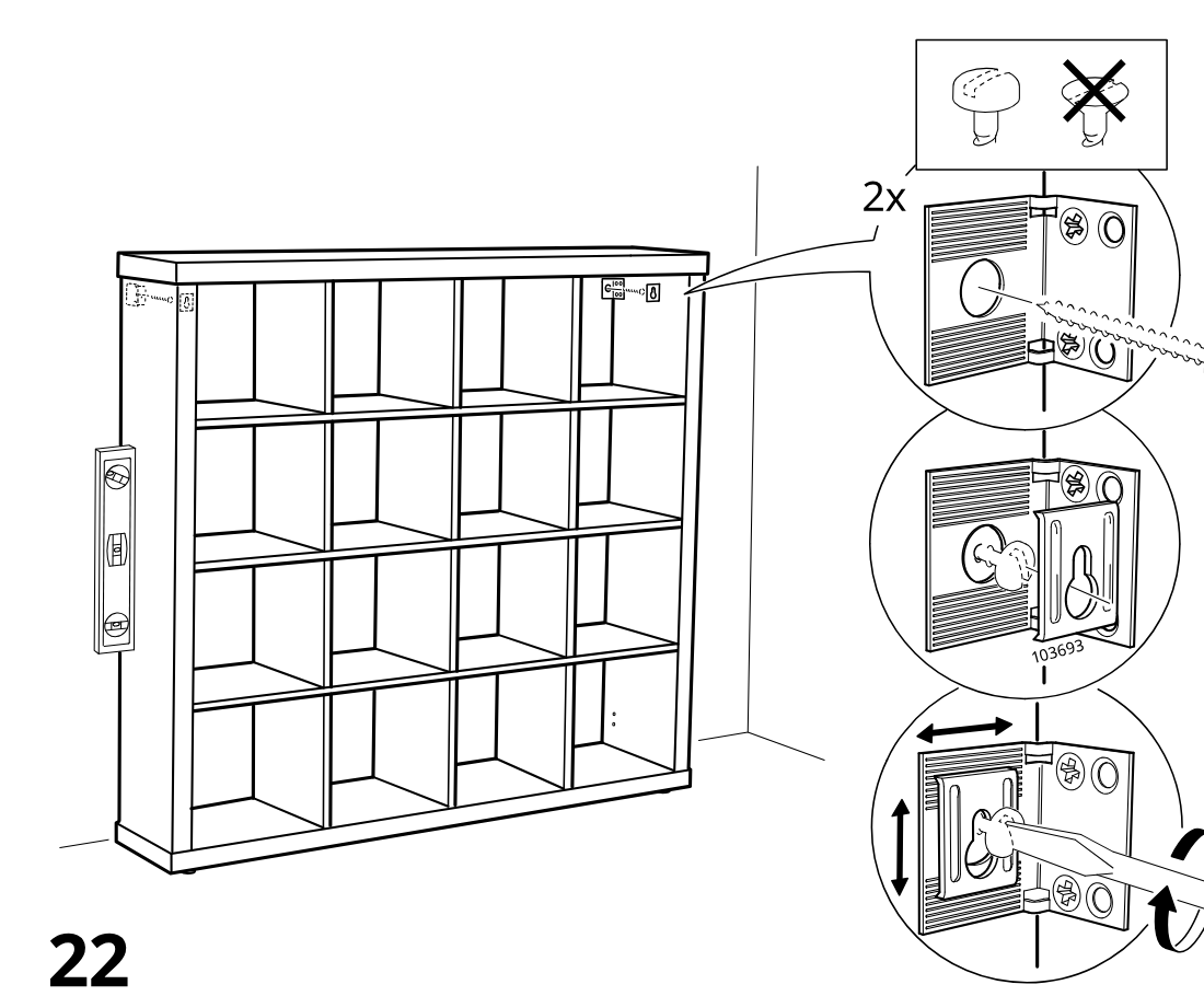
    Diagram for step 21: The shelving unit is leveled and secured to the wall at two upper brackets, then the wall fitting is attached and adjusted with a screwdriver.
  23. Step 22

    Two cover pieces are pushed onto the mounted wall fittings at the top side of the shelving unit.
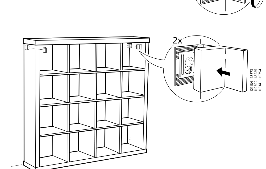
    Diagram for step 22: Two cover pieces are pushed onto the mounted wall fittings at the top side of the shelving unit.
  24. Step 23

    Two top brackets are set onto the shelving unit, inserted into the top holes, and their wall positions are marked with a pencil.
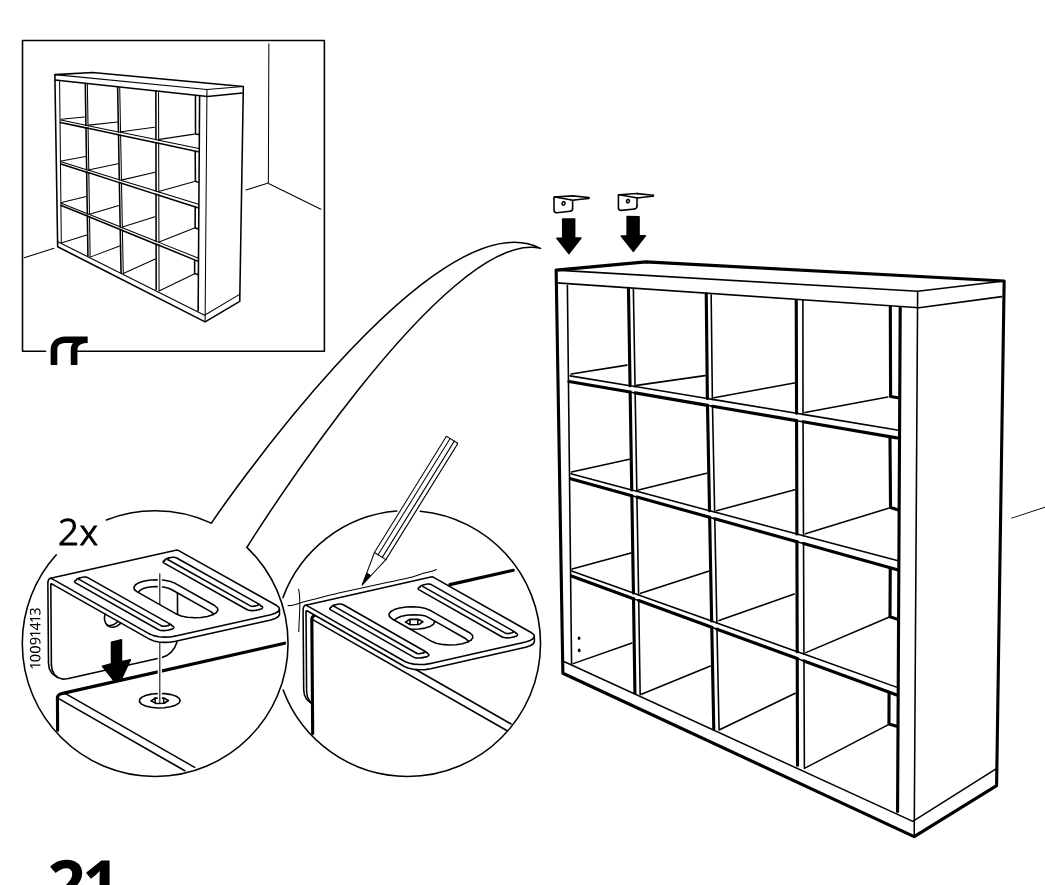
    Diagram for step 23: Two top brackets are set onto the shelving unit, inserted into the top holes, and their wall positions are marked with a pencil.
  25. Step 24

    Two screws are driven through the mounted brackets to secure the shelving unit to the wall, with an inset showing the correct screw type to use.
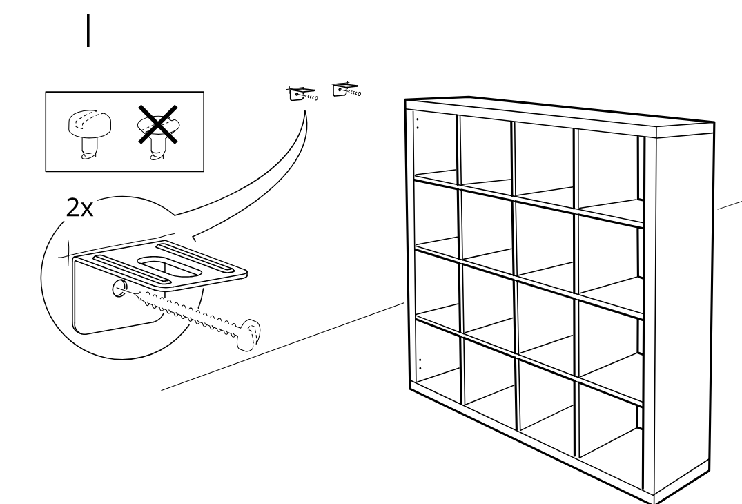
    Diagram for step 24: Two screws are driven through the mounted brackets to secure the shelving unit to the wall, with an inset showing the correct screw type to use.
  26. Step 25

    Two screws 104321/104322 are inserted and tightened from above into the top of the shelving unit, with two small angle brackets shown for the top edge.
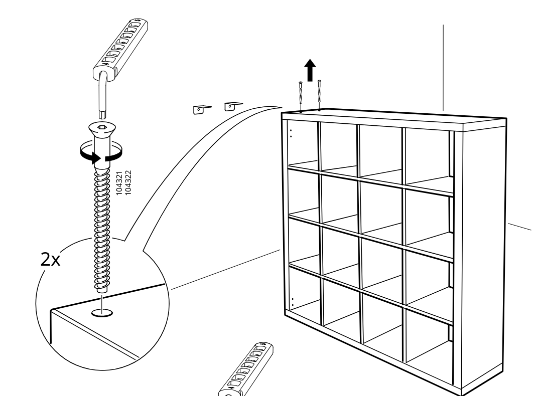
    Diagram for step 25: Two screws 104321/104322 are inserted and tightened from above into the top of the shelving unit, with two small angle brackets shown for the top edge.
  27. Step 26

    Two metal brackets are slid onto the top edge of the unit and secured by tightening two screws 104321/104322 downward from above.
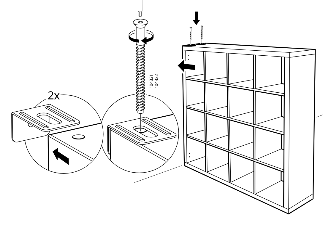
    Diagram for step 26: Two metal brackets are slid onto the top edge of the unit and secured by tightening two screws 104321/104322 downward from above.

Make it yours

Small additions. A better setup.

These optional additions are separate from any parts, safety equipment, or tools required to assemble the product.

Explore storage additions

Some links are affiliate links. We may earn a commission if you buy through them, at no extra cost to you. As an Amazon Associate, we earn from qualifying purchases.

  • Amazon Basics fabric storage cubes, beige (6-pack)

    Soft cubes add removable storage to open KALLAX compartments.

    Each cube is 10.5 × 10.5 × 11 in (26.7 × 26.7 × 27.9 cm), smaller than the 33 × 33 × 39 cm KALLAX opening. Seams, handles, or inserts can reduce clearance; do not force a cube.

    View product
  • Officemate weighted bookends, black (pair)

    A padded, freestanding bookend keeps a short row of books upright in a KALLAX cubby.

    Use one bookend per cubby, with the cubby wall supporting the other end; the pair can serve two cubbies. Do not put both bases side by side in one cubby. Keep total shelf load within IKEA’s 13 kg limit.

    Image reuse rights have not been independently verified.

    View product
  • Simple Houseware magazine files, white (6-pack)

    Upright files keep magazines and light papers tidy in a KALLAX cubby.

    Each file is 24.77 × 9.53 × 31.12 cm; the KALLAX opening is 33 × 33 × 39 cm. Three span about 28.6 cm, with under 2 cm height clearance. Check the assembled fit, use for light papers only, and do not force them.

    Image reuse rights have not been independently verified.

    View product
  • Amazon Basics freestanding cabinet shelf, white (2-pack)

    A small freestanding shelf adds a second level inside a KALLAX cubby.

    Each 31.75 × 20.32 × 11.43 cm shelf fits within a 33 × 33 × 39 cm cubby. Use for lightweight items only; the listing gives no shelf load rating, and total KALLAX load must stay within 13 kg.

    Image reuse rights have not been independently verified.

    View product

Video guide