How to assemble IKEA LOMMARP Cabinet with glass doors

LOMMARP Cabinet with glass doors, dark blue-green, 33 7/8x78 3/8"

This guide covers the IKEA LOMMARP cabinet with glass doors in dark blue-green, article 403.837.37. Follow the cabinet assembly diagrams and video for this variant.

View on IKEA
LOMMARP Cabinet with glass doors

Interactive assembly guide

Step-by-Step Instructions

1 different parts, 1 boxes total — click on a package to see step-by-step assembly instructions

LOMMARP Cabinet with glass doors

403.837.37

x1

19 ¾ "

Width

3 ½ "

Height

34 "

Length

52 lb 13 oz

Weight

Start Assembly

Written guide

Step-by-step instructions with diagrams

Follow the numbered assembly steps below, or open the interactive guide above to track progress and zoom into each diagram. This guide includes 60 illustrated steps.

LOMMARP Cabinet with glass doors

  1. Before you begin

    Preparation and safety panels show to use correct screwdrivers, avoid assembling alone, avoid working on hard/dirty surfaces or damaging parts, and contact IKEA for help if unsure.
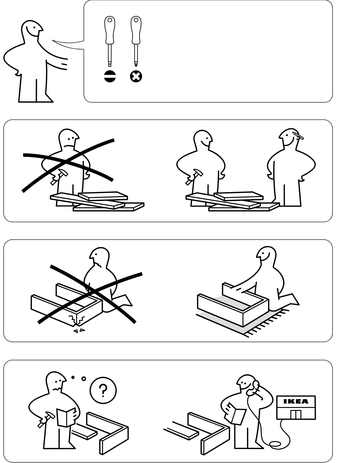
    Illustration for assembly note: Preparation and safety panels show to use correct screwdrivers, avoid assembling alone, avoid working on hard/dirty surfaces or damaging parts, and contact IKEA for help if unsure.
  2. Before you begin

    Parts-bag panel 2 showing required hardware and fittings with quantities for this stage, plus a page-turn icon referencing page 14.
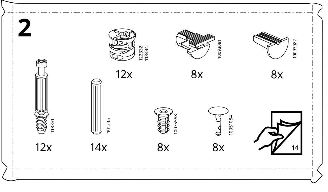
    Illustration for assembly note: Parts-bag panel 2 showing required hardware and fittings with quantities for this stage, plus a page-turn icon referencing page 14.
  3. Before you begin

    Parts-bag panel 3 showing required hardware, fittings, and bracket parts with quantities for this stage, plus a page-turn icon referencing page 20.
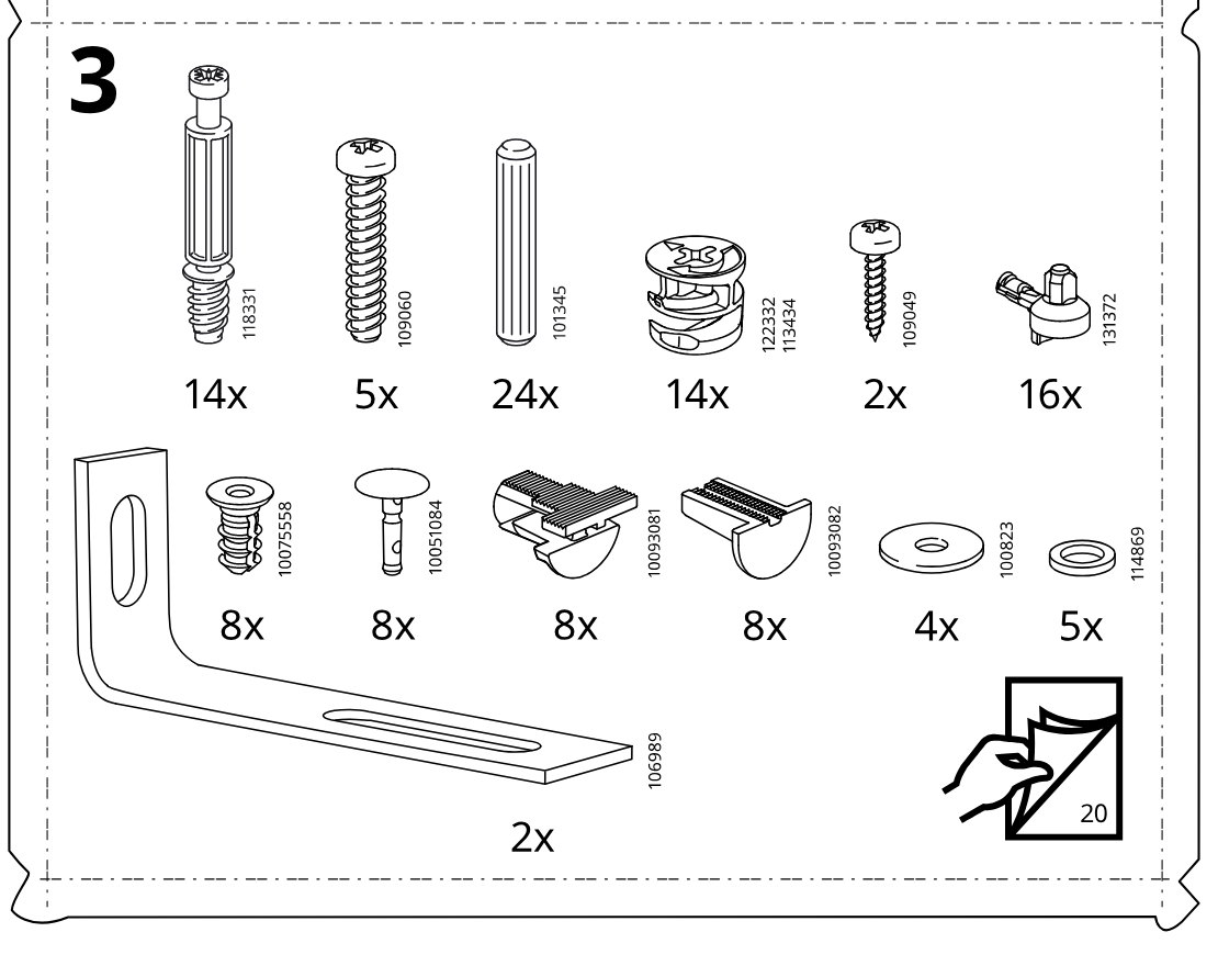
    Illustration for assembly note: Parts-bag panel 3 showing required hardware, fittings, and bracket parts with quantities for this stage, plus a page-turn icon referencing page 20.
  4. Before you begin

    Parts-bag reference panel for step 4 showing required hardware and components with quantities (10006275 x2, 10006309 x2, 119976 x2, 151743 x2, 107091 x2) and a note to see page 33.
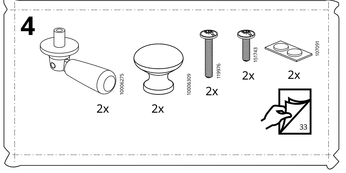
    Illustration for assembly note: Parts-bag reference panel for step 4 showing required hardware and components with quantities (10006275 x2, 10006309 x2, 119976 x2, 151743 x2, 107091 x2) and a note to see page 33.
  5. Before you begin

    Reference panel showing hinge assembly variant 10031752 with quantity 4x.
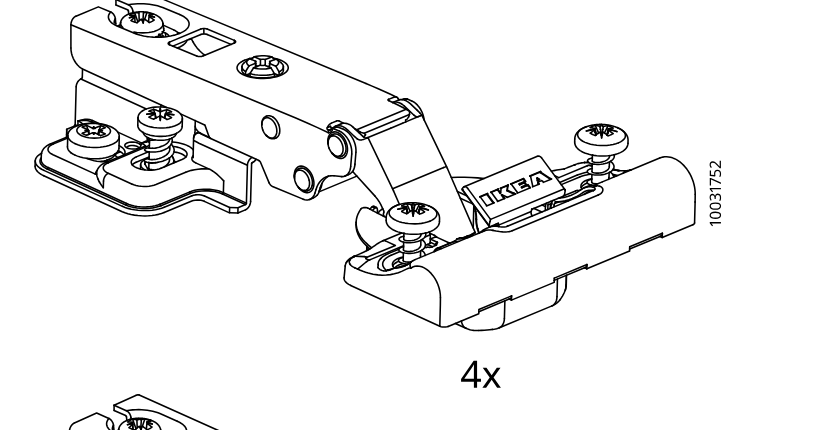
    Illustration for assembly note: Reference panel showing hinge assembly variant 10031752 with quantity 4x.
  6. Before you begin

    Reference panel showing hinge assembly variant 146884 with quantity 4x.
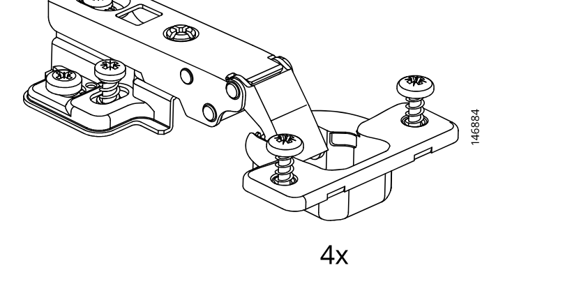
    Illustration for assembly note: Reference panel showing hinge assembly variant 146884 with quantity 4x.
  7. Step 1

    Insert and screw in two 100481 cam bolts into the frame end holes with correct depth, as indicated by the do/don't inset.
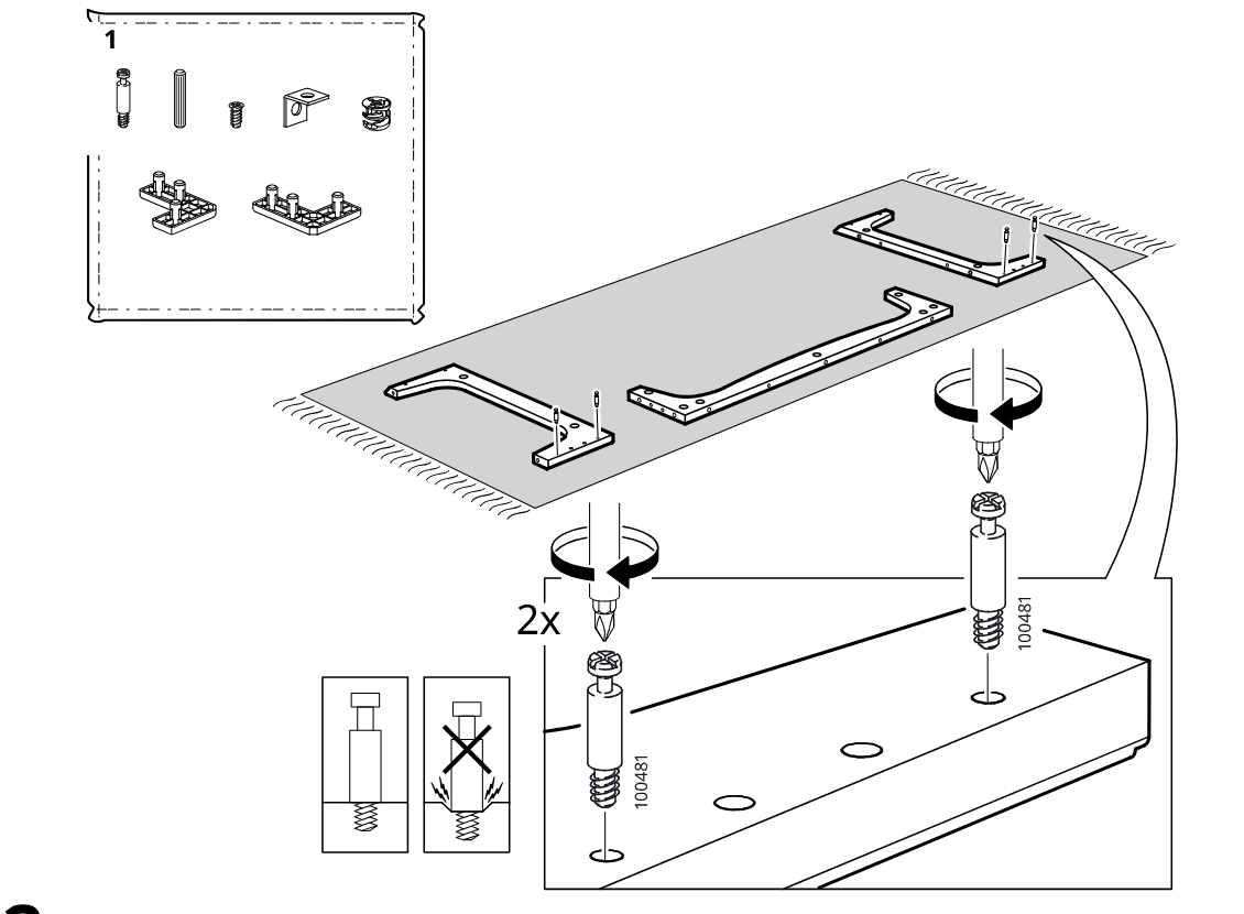
    Diagram for step 1: Insert and screw in two 100481 cam bolts into the frame end holes with correct depth, as indicated by the do/don't inset.
  8. Step 2

    Push four 101345 dowels into the aligned connector holes between the long and side frame sections.
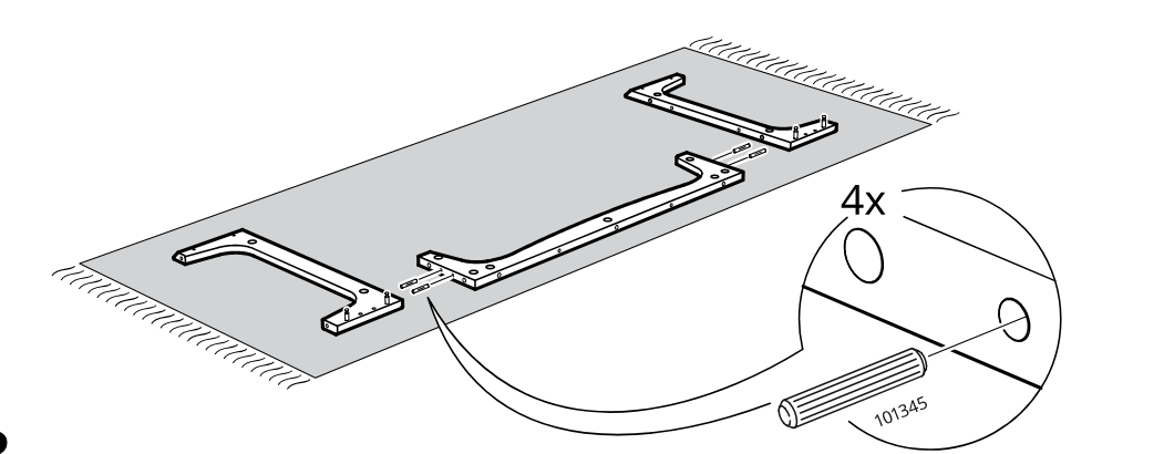
    Diagram for step 2: Push four 101345 dowels into the aligned connector holes between the long and side frame sections.
  9. Step 3

    Rotate and fold the connected frame sections upright around the joints to form the standing frame shape.
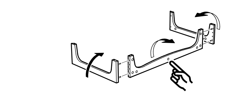
    Diagram for step 3: Rotate and fold the connected frame sections upright around the joints to form the standing frame shape.
  10. Step 4

    The side frame pieces are joined with cam fittings and then rotated into the shown orientation.
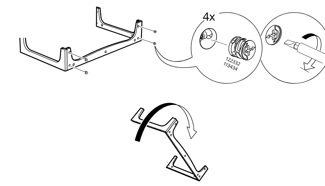
    Diagram for step 4: The side frame pieces are joined with cam fittings and then rotated into the shown orientation.
  11. Step 5

    Six wooden dowels are inserted into the top edges of the assembled frame.
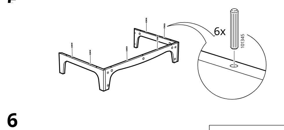
    Diagram for step 5: Six wooden dowels are inserted into the top edges of the assembled frame.
  12. Step 6

    Angle brackets and screws are fastened to the long rail and panel, with close-ups indicating edge orientation and corner wrap direction.
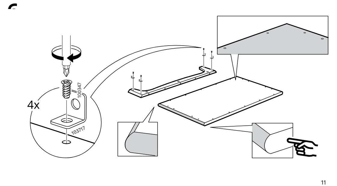
    Diagram for step 6: Angle brackets and screws are fastened to the long rail and panel, with close-ups indicating edge orientation and corner wrap direction.
  13. Step 7

    Insert two wooden dowels into the small rail piece and align the rail with the pilot holes on the large panel.
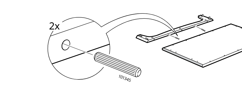
    Diagram for step 7: Insert two wooden dowels into the small rail piece and align the rail with the pilot holes on the large panel.
  14. Step 8

    Screw ten cam bolts into the panel holes by hand and turn them in the correct direction as indicated before assembly.
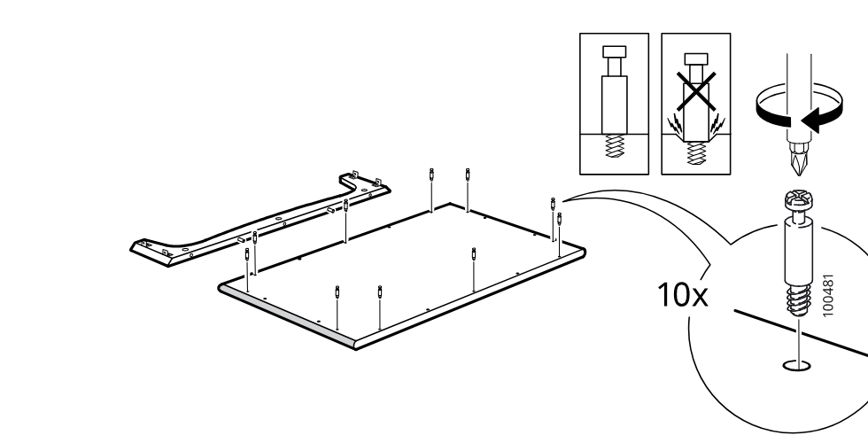
    Diagram for step 8: Screw ten cam bolts into the panel holes by hand and turn them in the correct direction as indicated before assembly.
  15. Step 9

    Lower the large U-shaped frame onto the prepared base panel so the frame aligns with and seats onto the installed connectors.
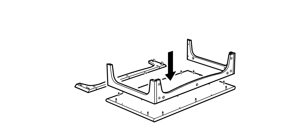
    Diagram for step 9: Lower the large U-shaped frame onto the prepared base panel so the frame aligns with and seats onto the installed connectors.
  16. Step 10

    The side frame is lowered onto the base frame and aligned at the corner posts.
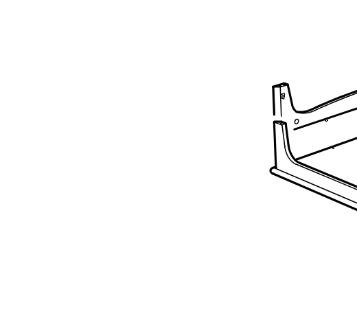
    Diagram for step 10: The side frame is lowered onto the base frame and aligned at the corner posts.
  17. Step 11

    Four corner caps are placed by matching A and B orientations, then pressed onto the four top posts.
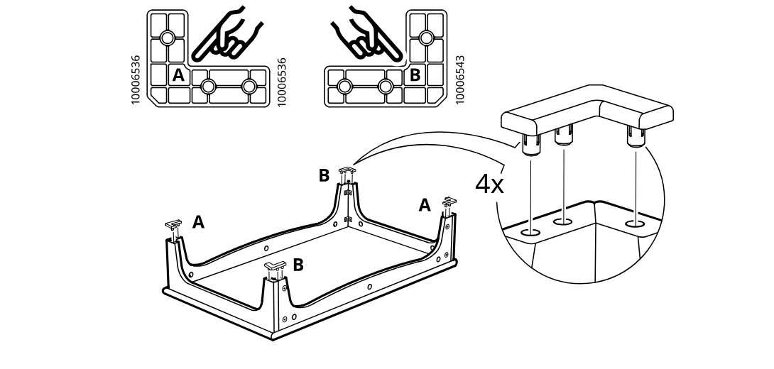
    Diagram for step 11: Four corner caps are placed by matching A and B orientations, then pressed onto the four top posts.
  18. Step 12

    Four screws are driven into the corner bracket inserts to secure the frame.
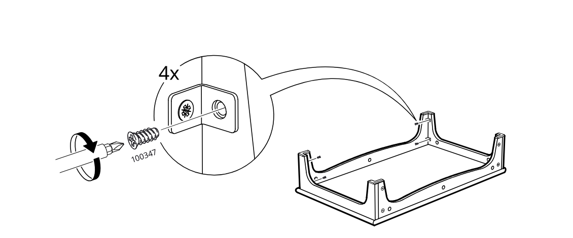
    Diagram for step 12: Four screws are driven into the corner bracket inserts to secure the frame.
  19. Step 13

    The frame is assembled with cam fittings and then rotated upright as indicated by the large curved arrow.
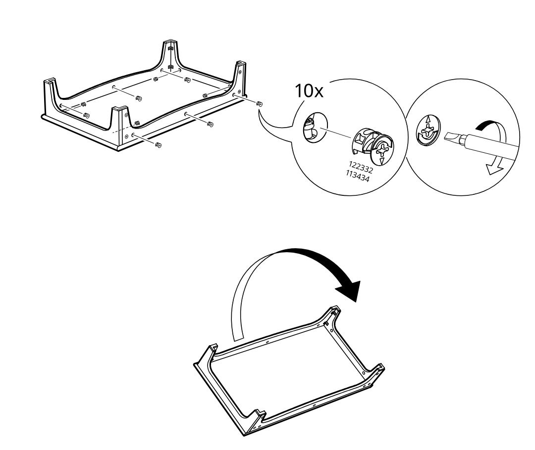
    Diagram for step 13: The frame is assembled with cam fittings and then rotated upright as indicated by the large curved arrow.
  20. Step 14

    Four cam screws are installed into the board top holes using a screwdriver, with the hand icon indicating the correct side and the inset showing 4x placement.
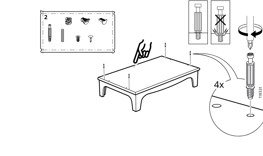
    Diagram for step 14: Four cam screws are installed into the board top holes using a screwdriver, with the hand icon indicating the correct side and the inset showing 4x placement.
  21. Step 15

    The installer screws four 118331 fasteners into the indicated holes on the two flat panels, with a close-up showing correct insertion depth and orientation.
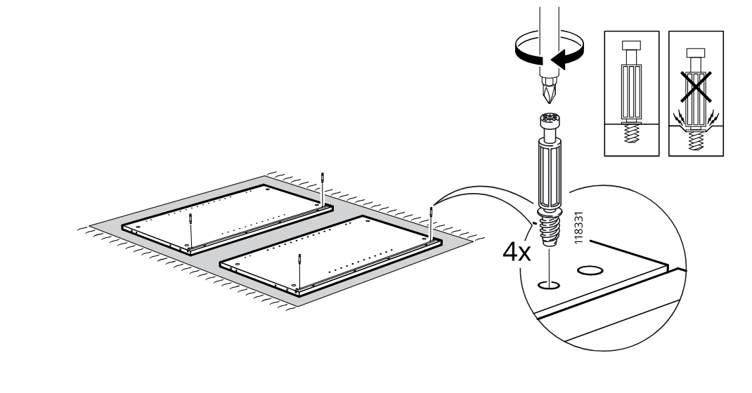
    Diagram for step 15: The installer screws four 118331 fasteners into the indicated holes on the two flat panels, with a close-up showing correct insertion depth and orientation.
  22. Step 16

    The installer identifies the correct side pieces, inserts four 101345 wooden dowels into their top holes, and positions the two side pieces upright onto the base panels.
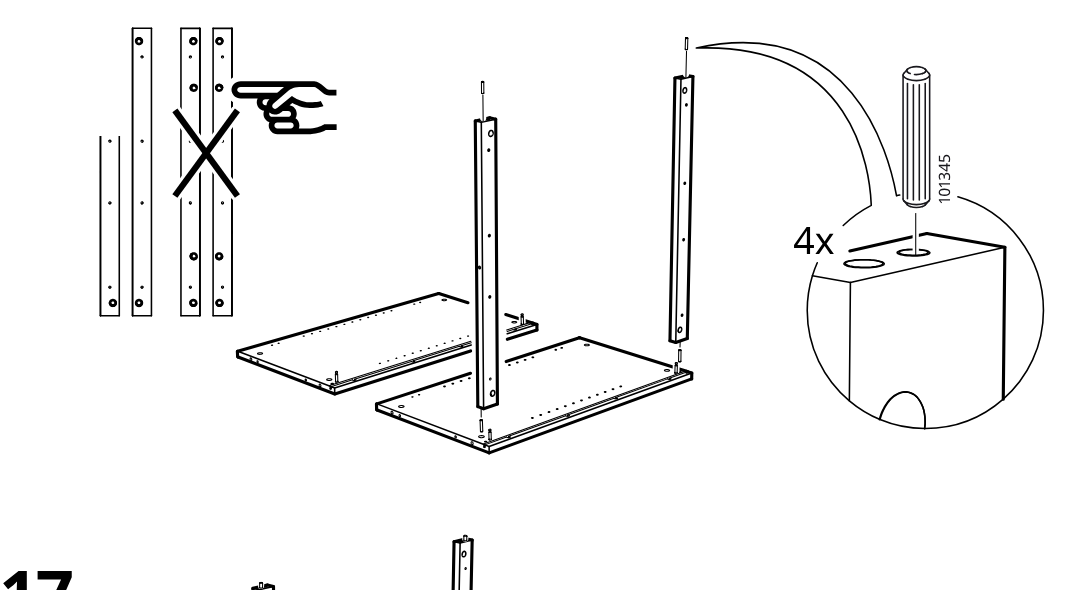
    Diagram for step 16: The installer identifies the correct side pieces, inserts four 101345 wooden dowels into their top holes, and positions the two side pieces upright onto the base panels.
  23. Step 17

    The installer locks two cam fittings (122332/113434) with a screwdriver to secure the upright side pieces to the panel assembly.
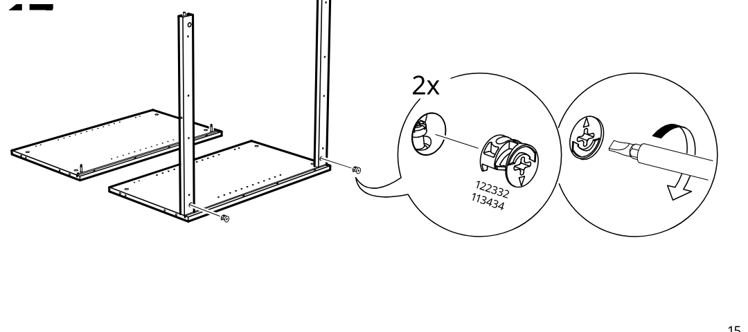
    Diagram for step 17: The installer locks two cam fittings (122332/113434) with a screwdriver to secure the upright side pieces to the panel assembly.
  24. Step 18

    The side/frame assembly is turned and positioned, then the inner panel is slid into place from the right side.
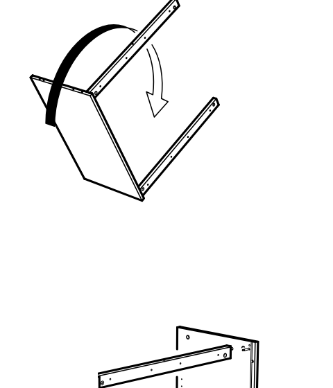
    Diagram for step 18: The side/frame assembly is turned and positioned, then the inner panel is slid into place from the right side.
  25. Step 19

    Two cam locks are inserted and tightened with a screwdriver to secure the panel within the cabinet frame.
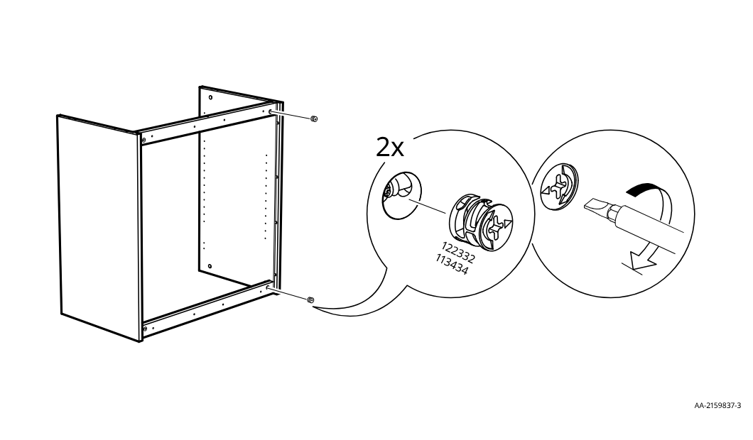
    Diagram for step 19: Two cam locks are inserted and tightened with a screwdriver to secure the panel within the cabinet frame.
  26. Step 20

    Ten dowels (101345) are inserted into the side panel and frame connection holes before joining the cabinet panels.
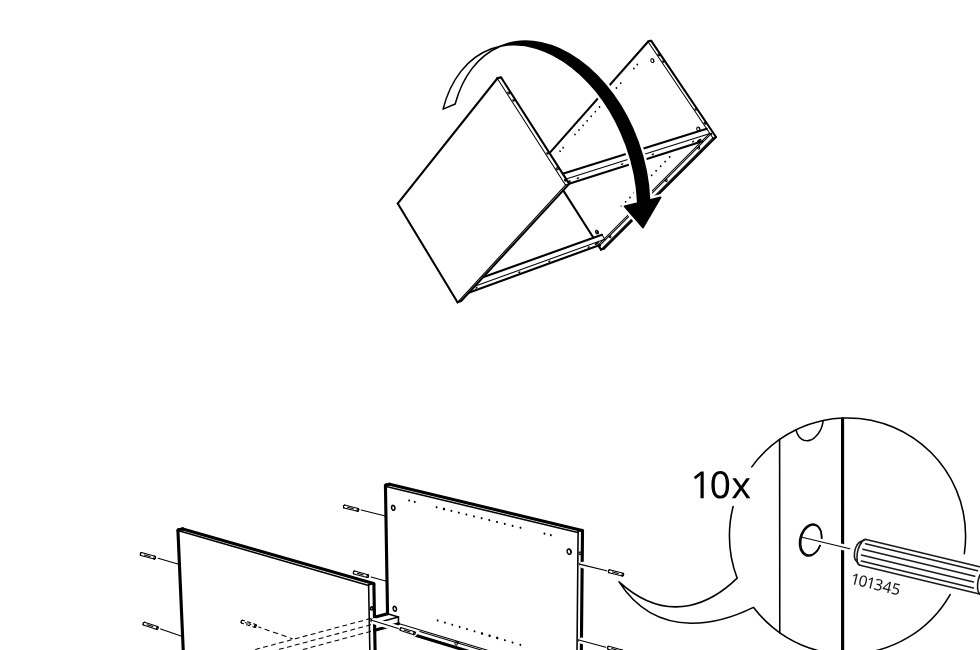
    Diagram for step 20: Ten dowels (101345) are inserted into the side panel and frame connection holes before joining the cabinet panels.
  27. Step 21

    The cabinet body is lowered straight down onto the base so the bottom holes align with the protruding dowels.
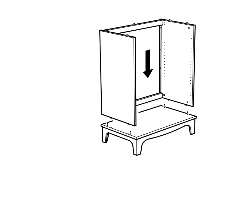
    Diagram for step 21: The cabinet body is lowered straight down onto the base so the bottom holes align with the protruding dowels.
  28. Step 22

    The cam fittings are inserted and turned with a screwdriver to lock the lower connection points of the cabinet frame.
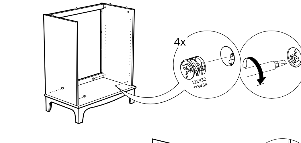
    Diagram for step 22: The cam fittings are inserted and turned with a screwdriver to lock the lower connection points of the cabinet frame.
  29. Step 23

    The correct rear panel orientation is shown and the panel is positioned into the cabinet grooves with the bottom edge seated in place.
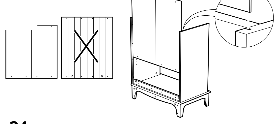
    Diagram for step 23: The correct rear panel orientation is shown and the panel is positioned into the cabinet grooves with the bottom edge seated in place.
  30. Step 24

    Four threaded fasteners are prepared in the panel and then tightened from above into the board to secure it to the unit.
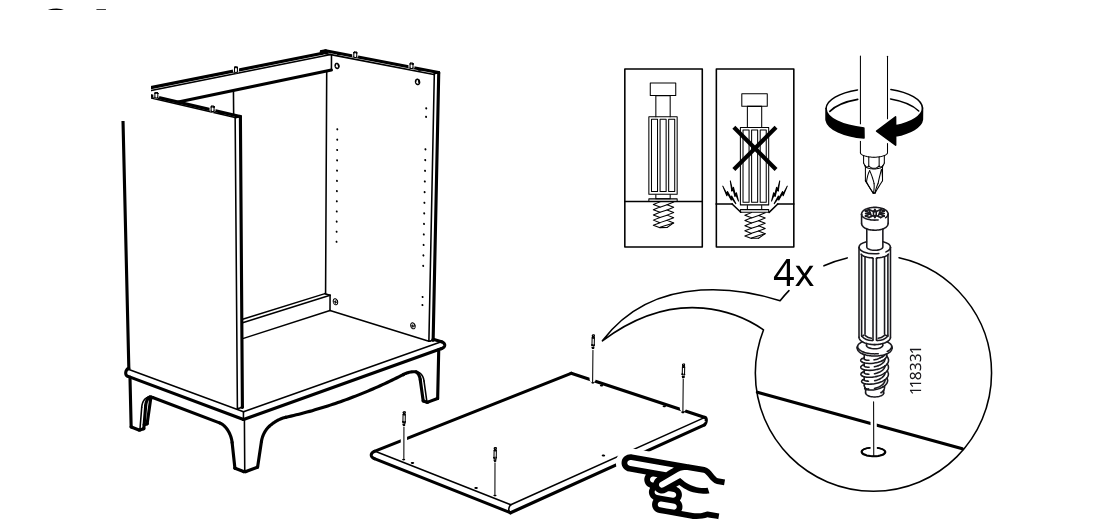
    Diagram for step 24: Four threaded fasteners are prepared in the panel and then tightened from above into the board to secure it to the unit.
  31. Step 25

    The top panel is lowered onto the cabinet frame, guided by a curved directional arrow.
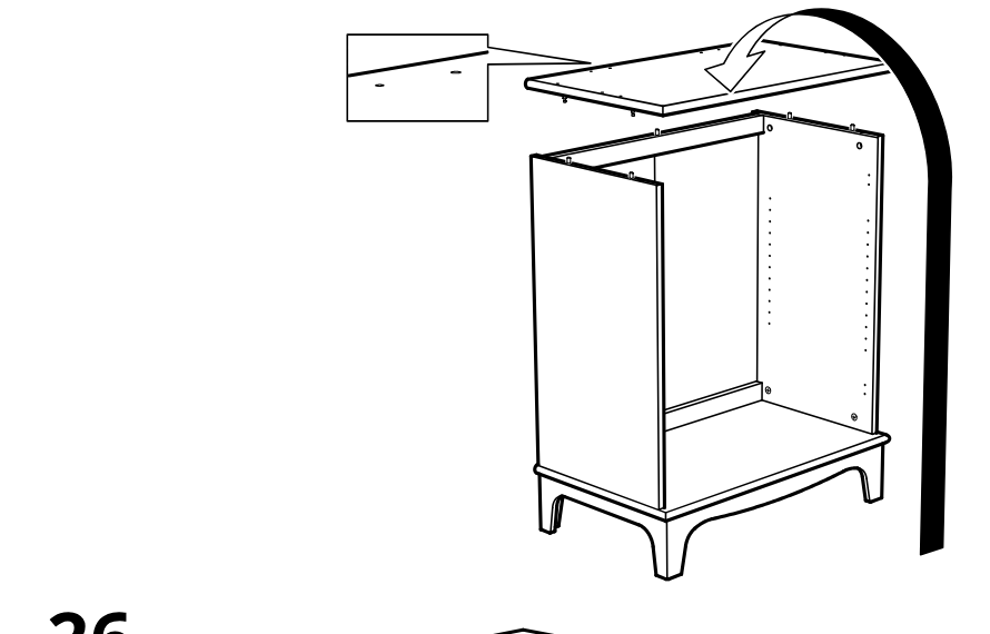
    Diagram for step 25: The top panel is lowered onto the cabinet frame, guided by a curved directional arrow.
  32. Step 26

    Four cam locks are inserted and then turned with a screwdriver to secure the top panel.
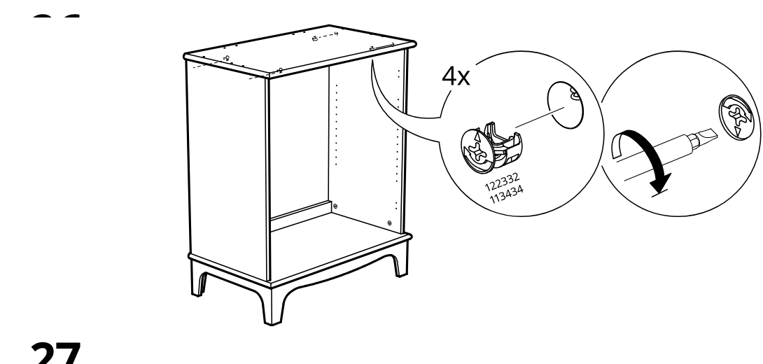
    Diagram for step 26: Four cam locks are inserted and then turned with a screwdriver to secure the top panel.
  33. Step 27

    Eight fasteners and matching caps are installed along the back and lower rails of the cabinet.
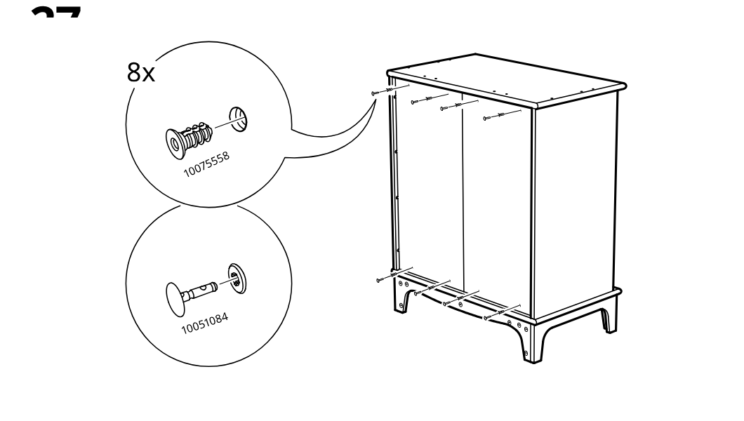
    Diagram for step 27: Eight fasteners and matching caps are installed along the back and lower rails of the cabinet.
  34. Step 28

    The installer inserts and snaps in the side-mounted fittings in sequence along the cabinet side, then presses the cover piece into place for all marked positions.
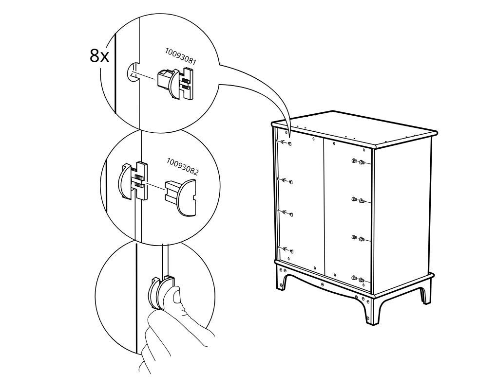
    Diagram for step 28: The installer inserts and snaps in the side-mounted fittings in sequence along the cabinet side, then presses the cover piece into place for all marked positions.
  35. Step 29

    The installer takes hardware from bag 3 and screws four 118331 inserts into the top holes with the correct orientation shown by the do/don’t guide.
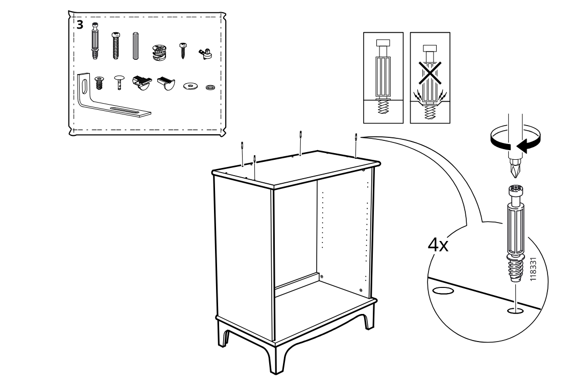
    Diagram for step 29: The installer takes hardware from bag 3 and screws four 118331 inserts into the top holes with the correct orientation shown by the do/don’t guide.
  36. Step 30

    The installer screws in four threaded inserts (part 118331) into the predrilled holes of the two panels, with a callout showing correct screwdriver use and a do-not-overdrive warning.
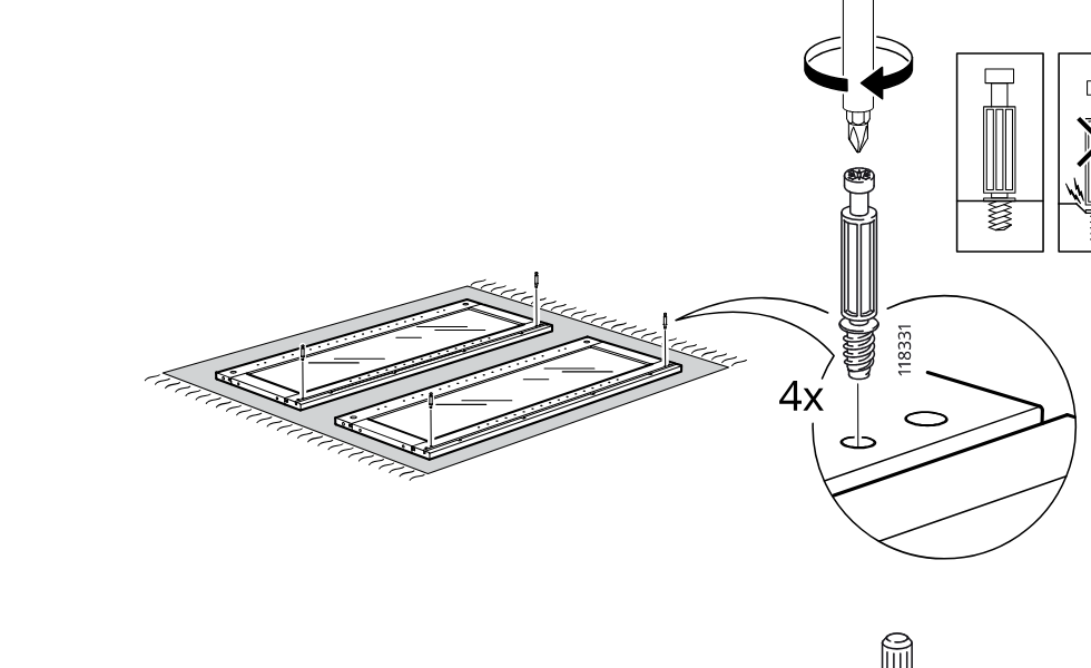
    Diagram for step 30: The installer screws in four threaded inserts (part 118331) into the predrilled holes of the two panels, with a callout showing correct screwdriver use and a do-not-overdrive warning.
  37. Step 31

    Two upright rails are positioned onto the panel assembly and four wooden dowels (part 101345) are inserted into the top holes, with an inset indicating rail orientation.
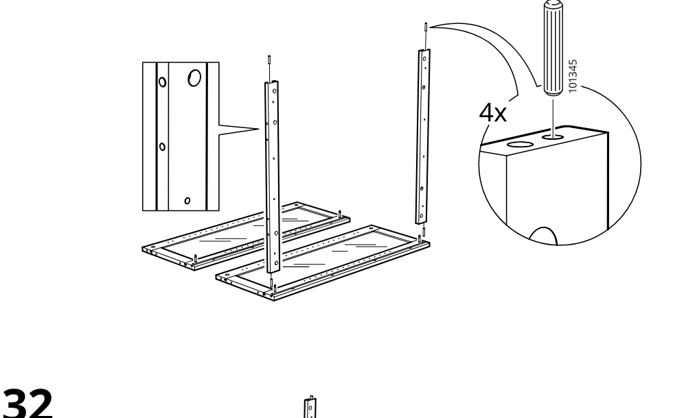
    Diagram for step 31: Two upright rails are positioned onto the panel assembly and four wooden dowels (part 101345) are inserted into the top holes, with an inset indicating rail orientation.
  38. Step 32

    Two cam locks (parts 122332/113434) are inserted into the side holes at the rail base and then turned with a screwdriver to lock the connection.
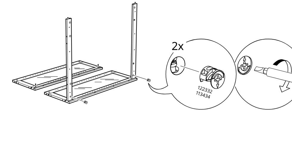
    Diagram for step 32: Two cam locks (parts 122332/113434) are inserted into the side holes at the rail base and then turned with a screwdriver to lock the connection.
  39. Step 33

    The side frame is rotated upright and aligned with the base and opposite frame to form the cabinet body.
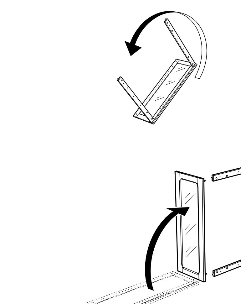
    Diagram for step 33: The side frame is rotated upright and aligned with the base and opposite frame to form the cabinet body.
  40. Step 34

    Two cam locks are inserted and turned to secure the newly attached side panel to the frame.
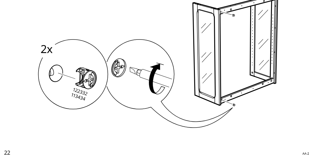
    Diagram for step 34: Two cam locks are inserted and turned to secure the newly attached side panel to the frame.
  41. Step 35

    Two dowels (101345) are inserted into the end holes of the two short rails.
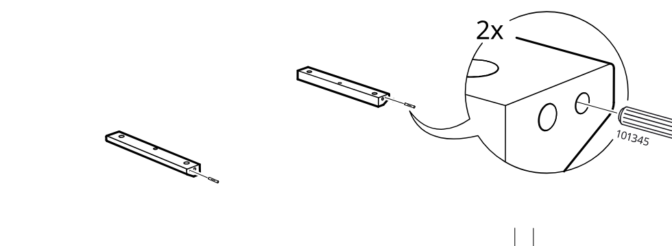
    Diagram for step 35: Two dowels (101345) are inserted into the end holes of the two short rails.
  42. Step 36

    Two cam screws (118331) are screwed into the long rail ends and the rail assembly is rotated into position.
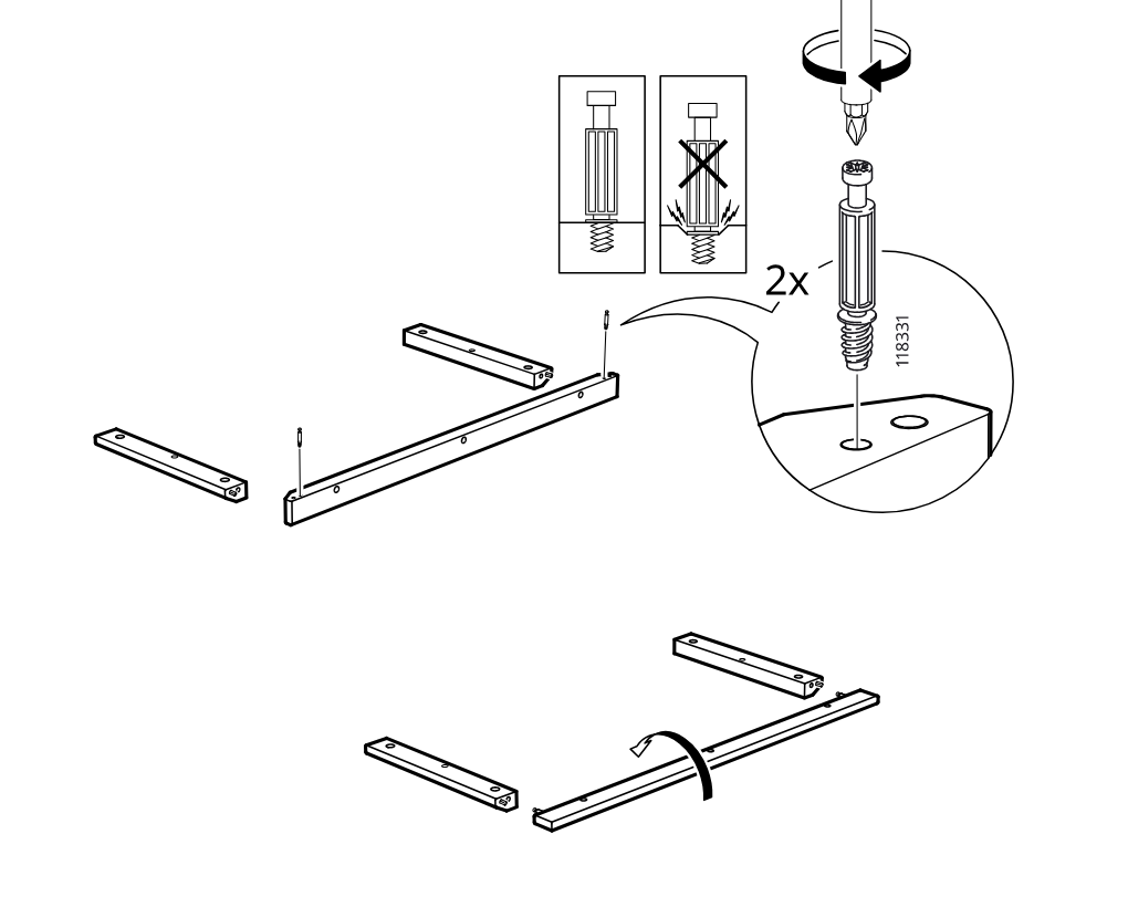
    Diagram for step 36: Two cam screws (118331) are screwed into the long rail ends and the rail assembly is rotated into position.
  43. Step 37

    Two cam locks (122332/113434) are inserted and turned with a screwdriver to lock the frame corners.
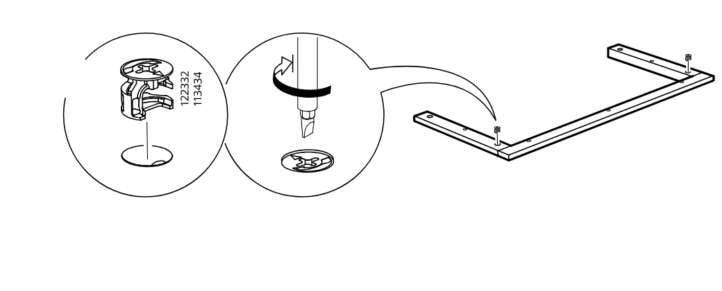
    Diagram for step 37: Two cam locks (122332/113434) are inserted and turned with a screwdriver to lock the frame corners.
  44. Step 38

    The frame is rotated and six wooden dowels (101345) are inserted into the predrilled holes along the frame.
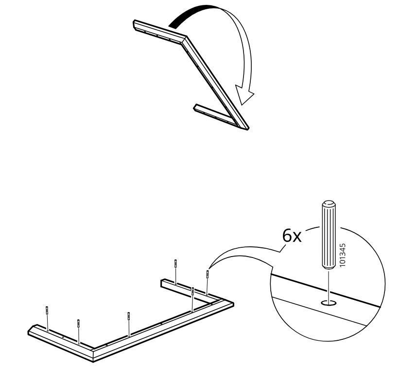
    Diagram for step 38: The frame is rotated and six wooden dowels (101345) are inserted into the predrilled holes along the frame.
  45. Step 39

    The frame is turned and lowered onto the large panel, aligning it before pressing it down into position.
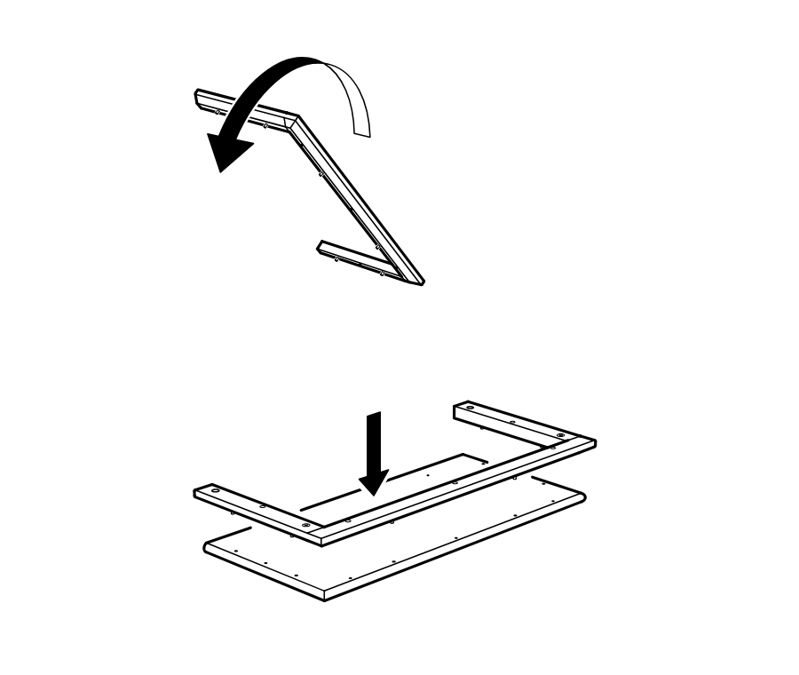
    Diagram for step 39: The frame is turned and lowered onto the large panel, aligning it before pressing it down into position.
  46. Step 40

    Insert five screws with washers into the panel, tighten from above, and rotate the panel as indicated.
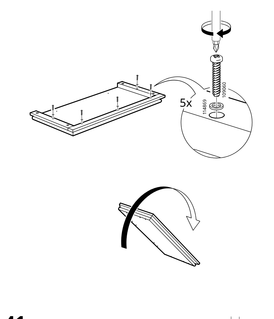
    Diagram for step 40: Insert five screws with washers into the panel, tighten from above, and rotate the panel as indicated.
  47. Step 41

    Screw in four cam bolts into the panel, tighten from above, and follow the orientation warning for correct insertion.
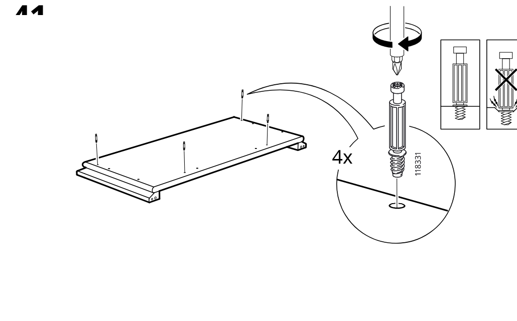
    Diagram for step 41: Screw in four cam bolts into the panel, tighten from above, and follow the orientation warning for correct insertion.
  48. Step 42

    Insert six dowels into the top holes of the cabinet frame as shown in the zoom detail.
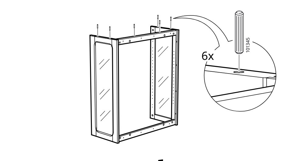
    Diagram for step 42: Insert six dowels into the top holes of the cabinet frame as shown in the zoom detail.
  49. Step 43

    Lower the top panel straight down onto the cabinet frame.
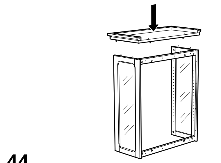
    Diagram for step 43: Lower the top panel straight down onto the cabinet frame.
  50. Step 44

    Install and turn four cam locks to secure the top panel to the cabinet frame.
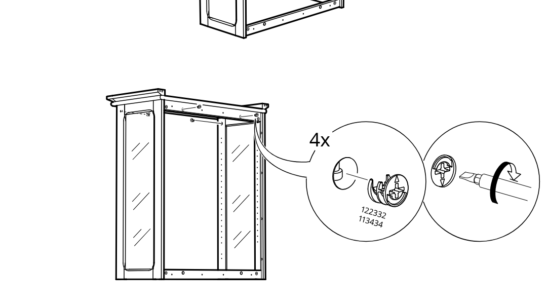
    Diagram for step 44: Install and turn four cam locks to secure the top panel to the cabinet frame.
  51. Step 45

    The builder places the large panel onto the frame and aligns its edge and holes, with a zoom callout showing the side slot alignment detail.
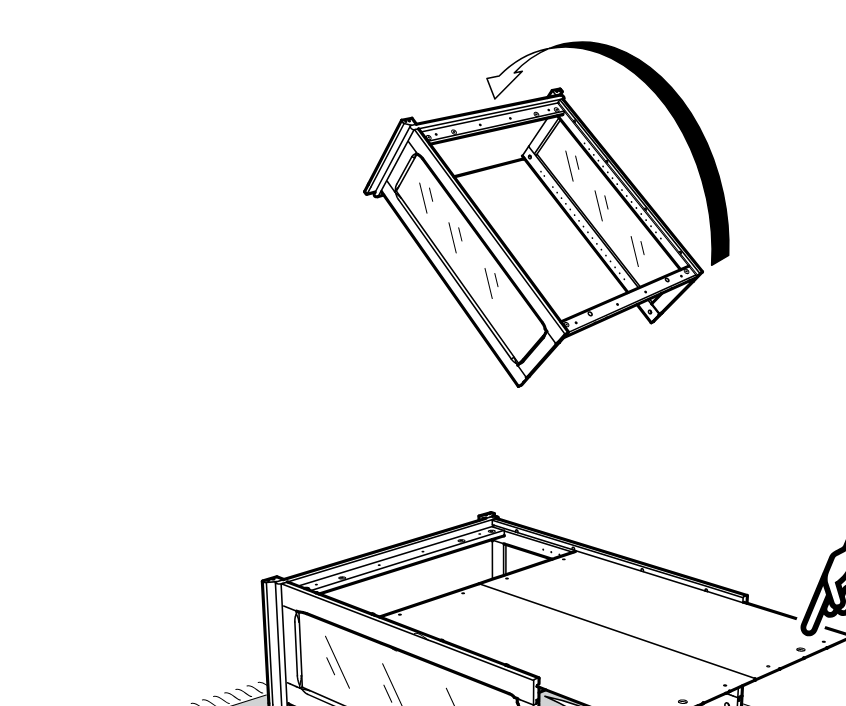
    Diagram for step 45: The builder places the large panel onto the frame and aligns its edge and holes, with a zoom callout showing the side slot alignment detail.
  52. Step 46

    The builder fastens the top panel with 8 screws and inserts 8 fittings from below, as shown in the two hardware zoom callouts.
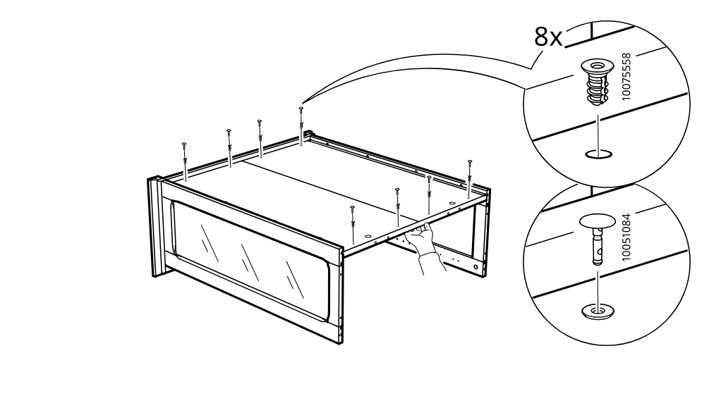
    Diagram for step 46: The builder fastens the top panel with 8 screws and inserts 8 fittings from below, as shown in the two hardware zoom callouts.
  53. Step 47

    The side panel assembly is positioned onto the cabinet top and two clip pieces (10093081 and 10093082) are installed in the indicated top slots 8 times.
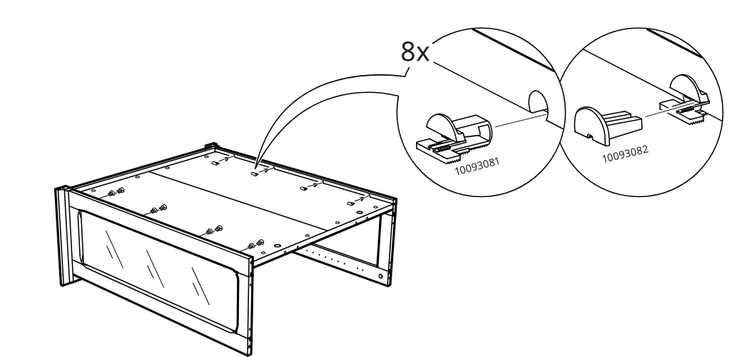
    Diagram for step 47: The side panel assembly is positioned onto the cabinet top and two clip pieces (10093081 and 10093082) are installed in the indicated top slots 8 times.
  54. Step 48

    Six wooden dowels (101345) are inserted into the side/frame holes to secure the upper section to the lower structure.
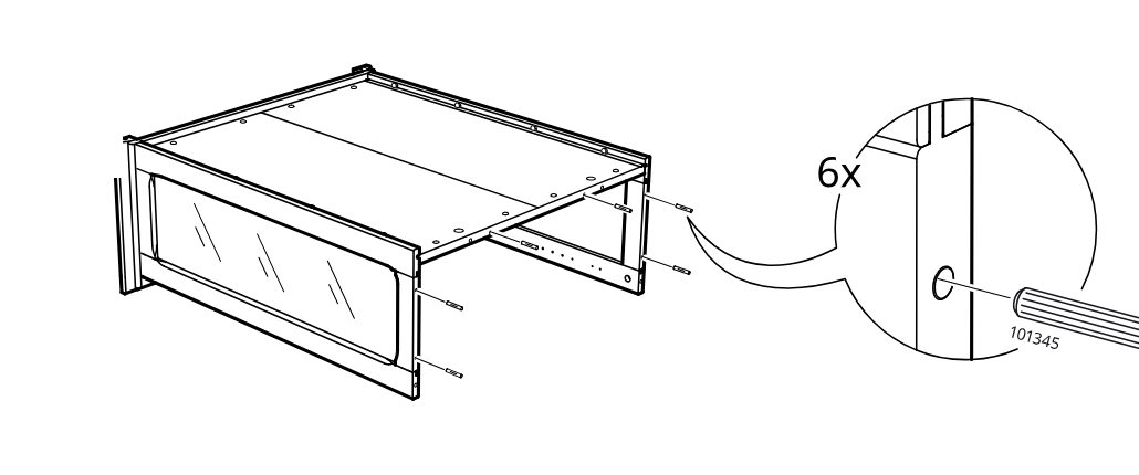
    Diagram for step 48: Six wooden dowels (101345) are inserted into the side/frame holes to secure the upper section to the lower structure.
  55. Step 49

    Two people lift and lower the assembled upper cabinet section onto the base, aligning it with the exposed dowels.
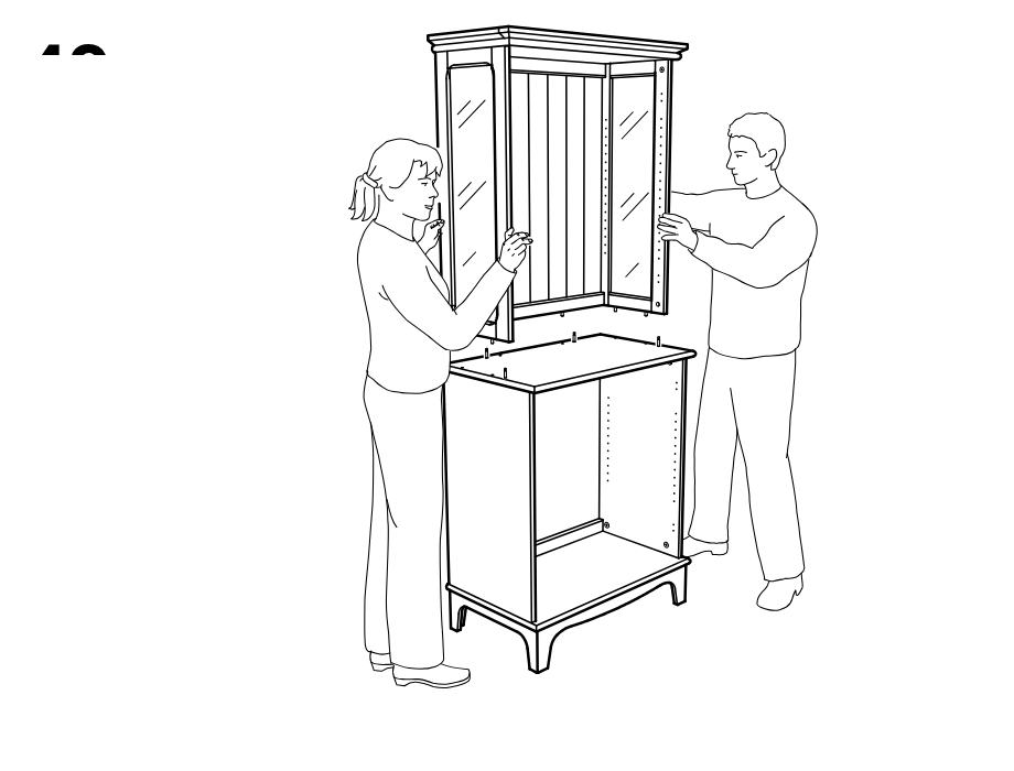
    Diagram for step 49: Two people lift and lower the assembled upper cabinet section onto the base, aligning it with the exposed dowels.
  56. Step 50

    The cam locks are inserted into the side panel holes and turned with a screwdriver to lock the upper section in place.
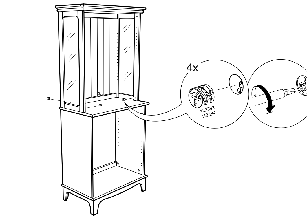
    Diagram for step 50: The cam locks are inserted into the side panel holes and turned with a screwdriver to lock the upper section in place.
  57. Step 51

    Two wall brackets are assembled with screws and washers, then screwed onto the top of the cabinet before positioning it against the wall.
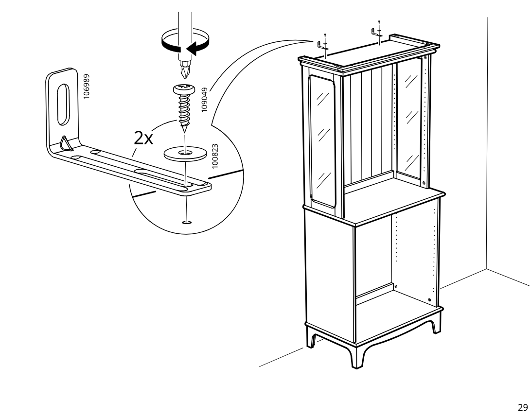
    Diagram for step 51: Two wall brackets are assembled with screws and washers, then screwed onto the top of the cabinet before positioning it against the wall.
  58. Step 52

    Install two screw covers/clips at the top side area, using the correct orientation shown in the inset, and fasten through the side panel with part 100823.
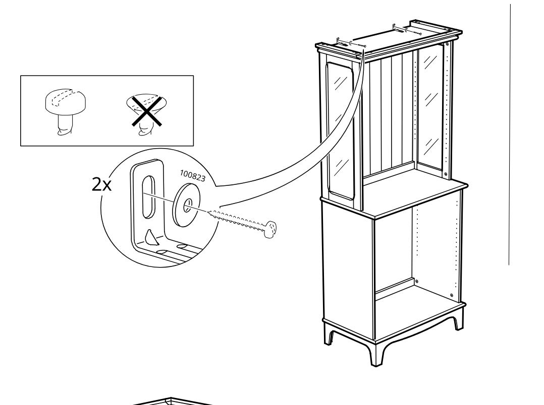
    Diagram for step 52: Install two screw covers/clips at the top side area, using the correct orientation shown in the inset, and fasten through the side panel with part 100823.
  59. Step 53

    Insert and tighten sixteen cam locks (part 131372) into the predrilled holes around the cabinet body and upper section.
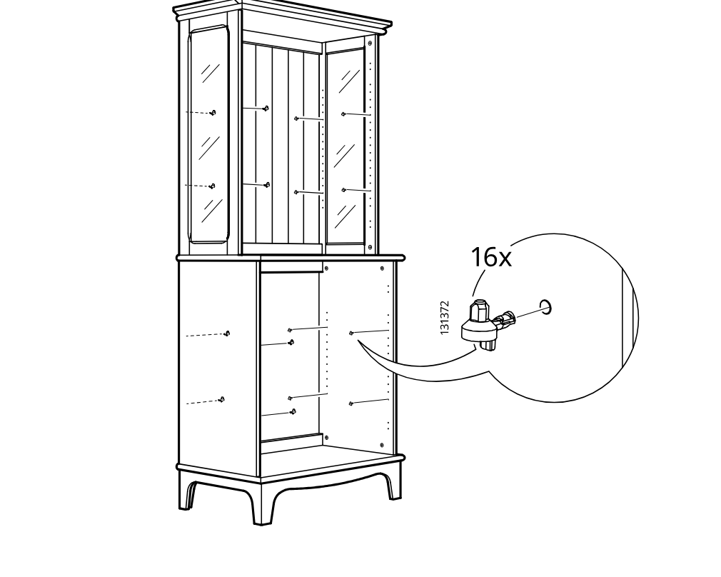
    Diagram for step 53: Insert and tighten sixteen cam locks (part 131372) into the predrilled holes around the cabinet body and upper section.
  60. Step 54

    The shelves are lowered into position inside the cabinet sections, with a zoom callout showing the shelf support peg engaged underneath.
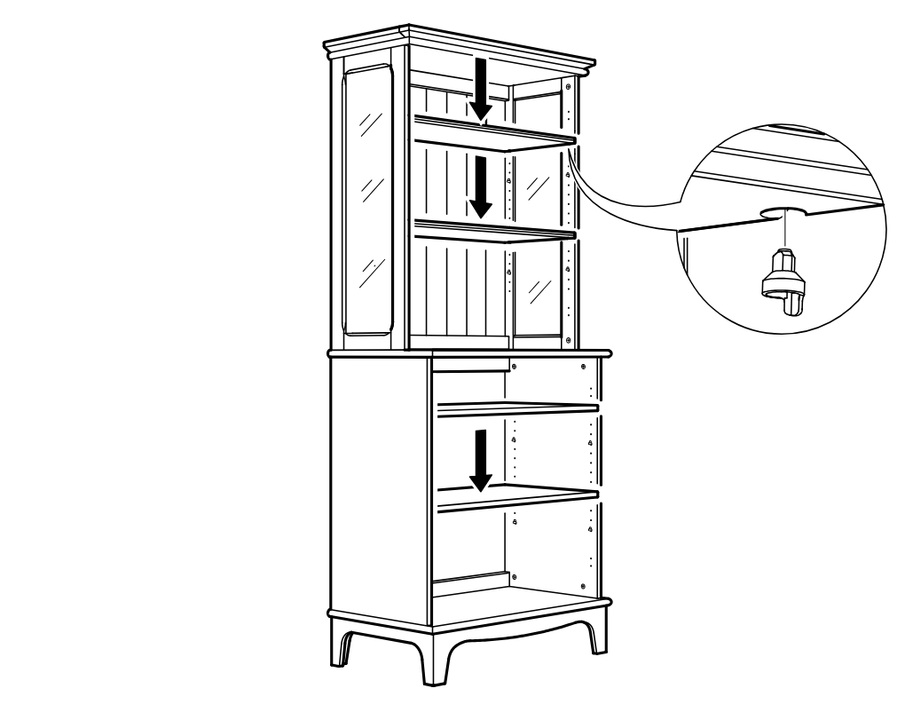
    Diagram for step 54: The shelves are lowered into position inside the cabinet sections, with a zoom callout showing the shelf support peg engaged underneath.
  61. Step 55

    Four hinges are fastened onto the door panels while they are laid flat, with the close-up indicating the screw locations and hinge orientation.
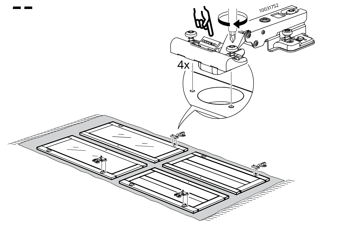
    Diagram for step 55: Four hinges are fastened onto the door panels while they are laid flat, with the close-up indicating the screw locations and hinge orientation.
  62. Step 56

    The hinge plates are positioned on the four door panels and secured with screws, with a close-up showing the screw positions and hinge part 146884.
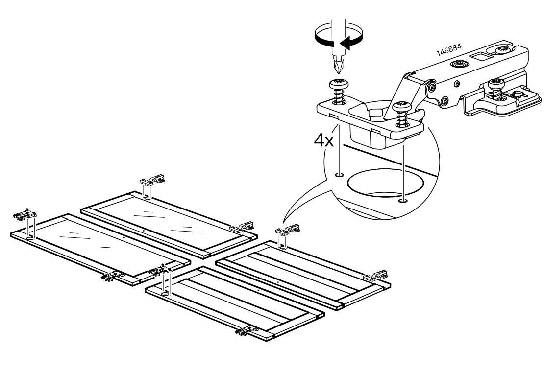
    Diagram for step 56: The hinge plates are positioned on the four door panels and secured with screws, with a close-up showing the screw positions and hinge part 146884.
  63. Step 57

    The cabinet doors are aligned and clipped onto the hinges, then the hinge adjustment screws are tightened and the latch element is pressed to lock, repeated for all eight hinge points.
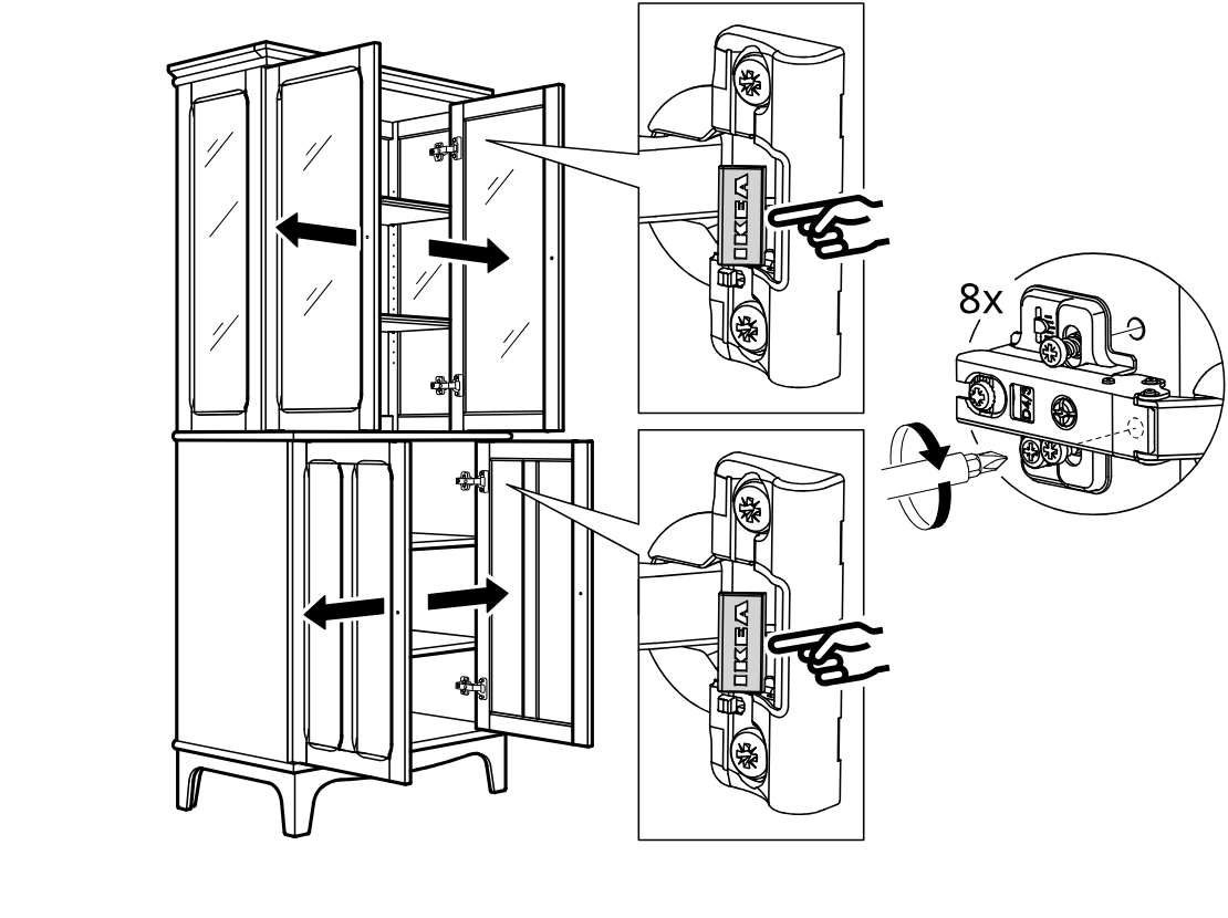
    Diagram for step 57: The cabinet doors are aligned and clipped onto the hinges, then the hinge adjustment screws are tightened and the latch element is pressed to lock, repeated for all eight hinge points.
  64. Step 58

    Install two screws into the upper door area and attach the lock cylinder/knob hardware as shown, using parts from bag 4.
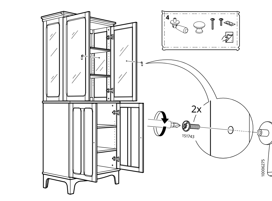
    Diagram for step 58: Install two screws into the upper door area and attach the lock cylinder/knob hardware as shown, using parts from bag 4.
  65. Step 59

    Install a screw in the lower door area and fasten the round knob assembly from the opposite side.
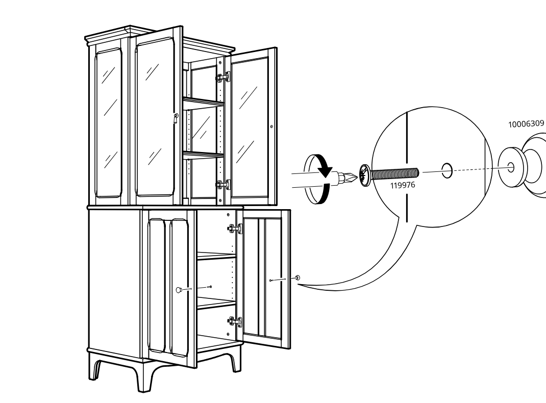
    Diagram for step 59: Install a screw in the lower door area and fasten the round knob assembly from the opposite side.
  66. Step 60

    Install four part 107091 bumpers onto the cabinet door/frame contact points as shown in the zoom callout.
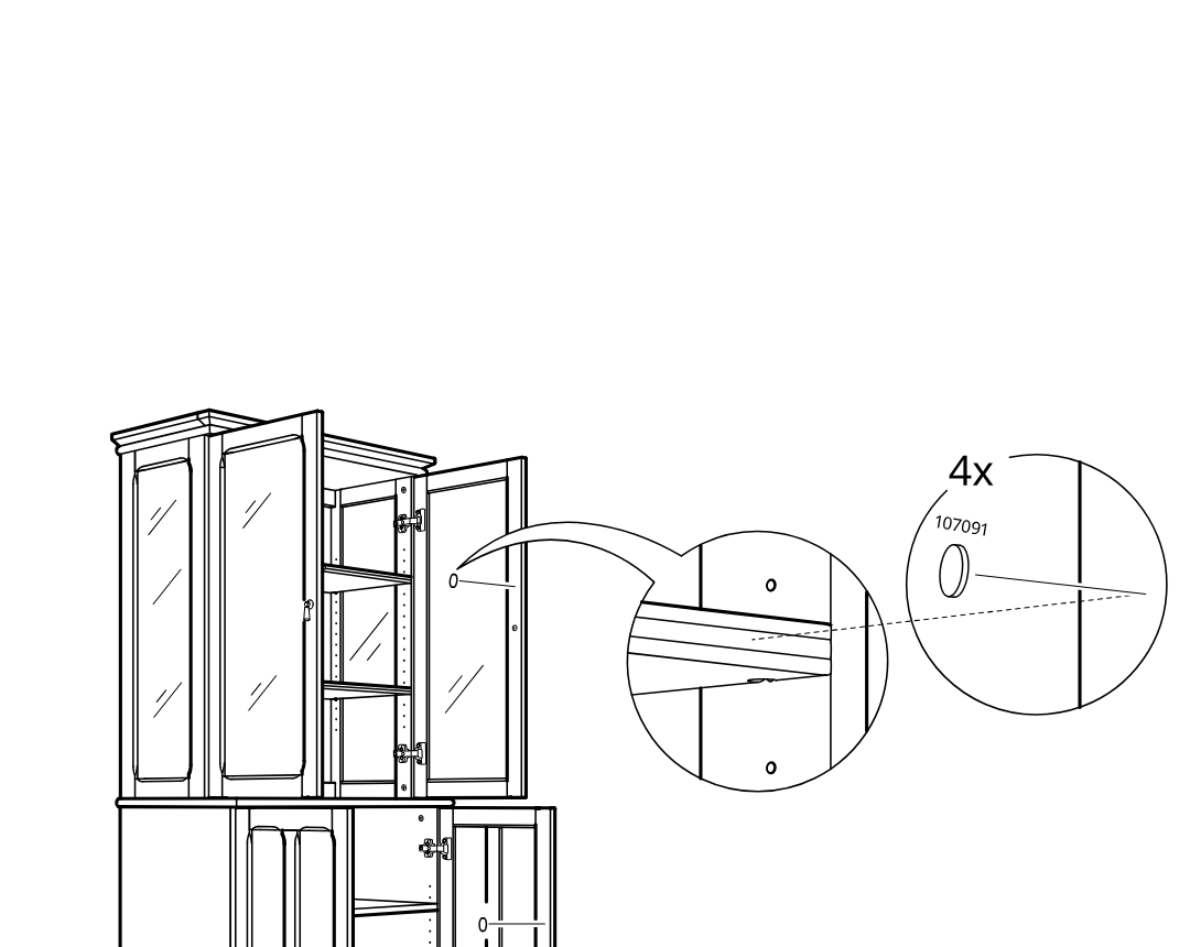
    Diagram for step 60: Install four part 107091 bumpers onto the cabinet door/frame contact points as shown in the zoom callout.
  67. Before you begin

    Information panel shows how to adjust cabinet door alignment on hinges using screwdriver screws for vertical and horizontal positioning with example cabinet views and close-up hinge diagrams.
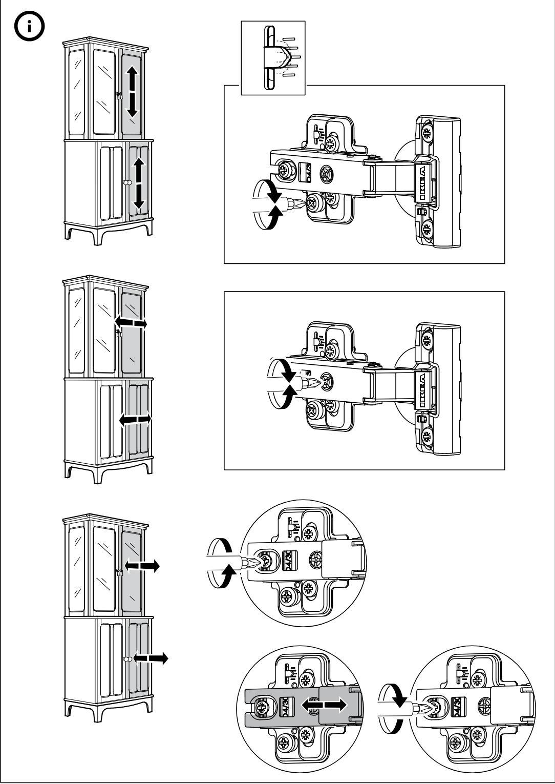
    Illustration for assembly note: Information panel shows how to adjust cabinet door alignment on hinges using screwdriver screws for vertical and horizontal positioning with example cabinet views and close-up hinge diagrams.

Video guide