How to assemble IKEA MALM 6-drawer dresser

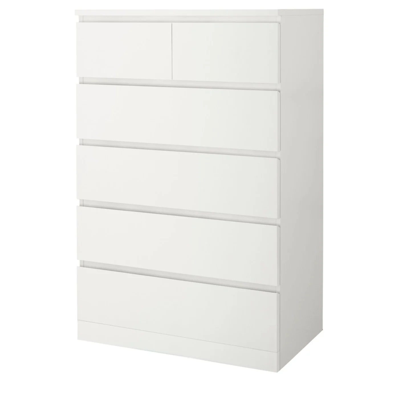
MALM 6-drawer dresser, white, 80x123 cm (31 1/2x48 3/8")

This guide covers the white IKEA MALM 6-drawer dresser, 80x123 cm, article 403.546.45. Choose the dresser-frame or drawer section for its assembly diagrams and video.

View on IKEA
MALM 6-drawer dresser

Interactive assembly guide

Step-by-Step Instructions

2 different parts, 3 boxes total — click on a package to see step-by-step assembly instructions

MALM 6-drawer dresser

403.546.45

x1

19 1/4 "

Width

4 "

Height

49 1/4 "

Length

65 lb 1 oz

Weight

Start Assembly

MALM 6-drawer dresser drawers

403.546.45

x2

18 "

Width

3 "

Height

37 3/4 "

Length

35 lb 11 oz

Weight

Start Assembly

Written guide

Step-by-step instructions with diagrams

Follow the numbered assembly steps below, or open the interactive guide above to track progress and zoom into each diagram. This guide includes 38 illustrated steps.

MALM 6-drawer dresser

  1. Step 1

    Install the indicated cam fittings and hardware into panels 118788 and 118789.
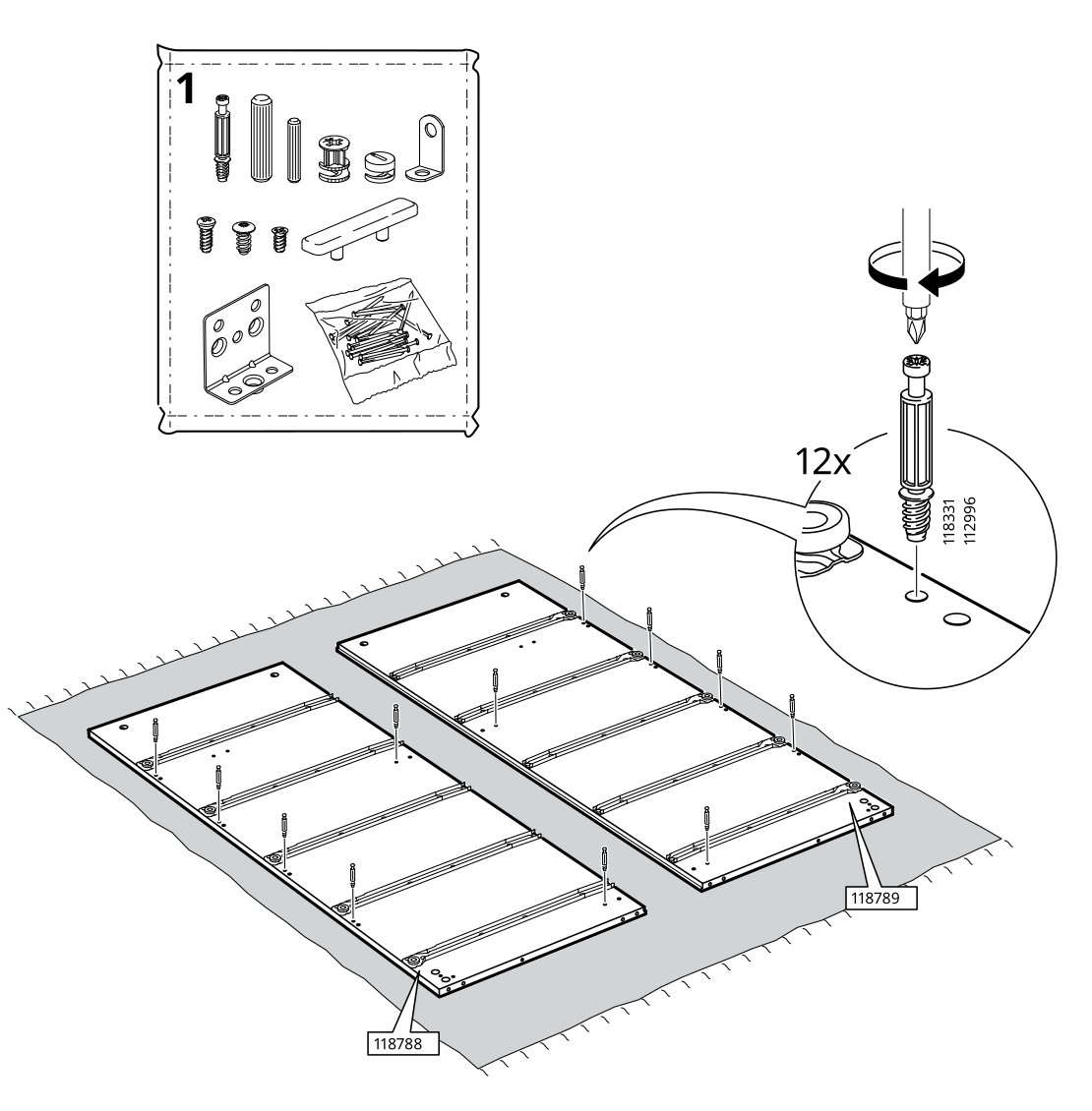
    Diagram for step 1: Install the indicated cam fittings and hardware into panels 118788 and 118789.
  2. Step 2

    Install four identified fittings onto the prepared drawer panels as shown.
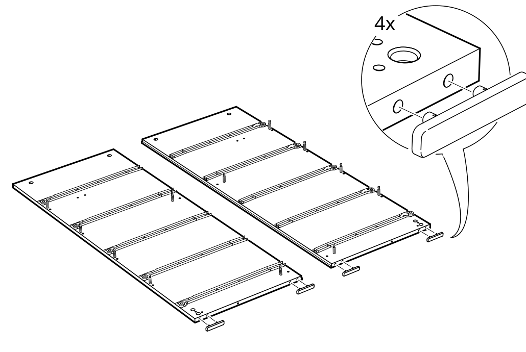
    Diagram for step 2: Install four identified fittings onto the prepared drawer panels as shown.
  3. Step 3

    Insert eight 101345 dowels into the panels and attach the four upright rails to the prepared assemblies.
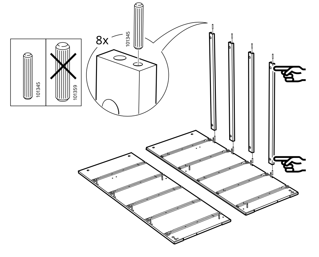
    Diagram for step 3: Insert eight 101345 dowels into the panels and attach the four upright rails to the prepared assemblies.
  4. Step 4

    Insert four 101345 cylindrical pins into the indicated holes and assemble the upright panels onto the base panels.
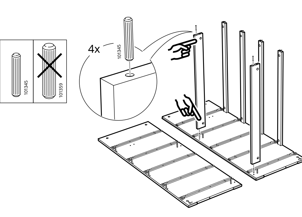
    Diagram for step 4: Insert four 101345 cylindrical pins into the indicated holes and assemble the upright panels onto the base panels.
  5. Step 5

    Install six 120076 cam locks in the indicated joints and tighten them with a screwdriver.
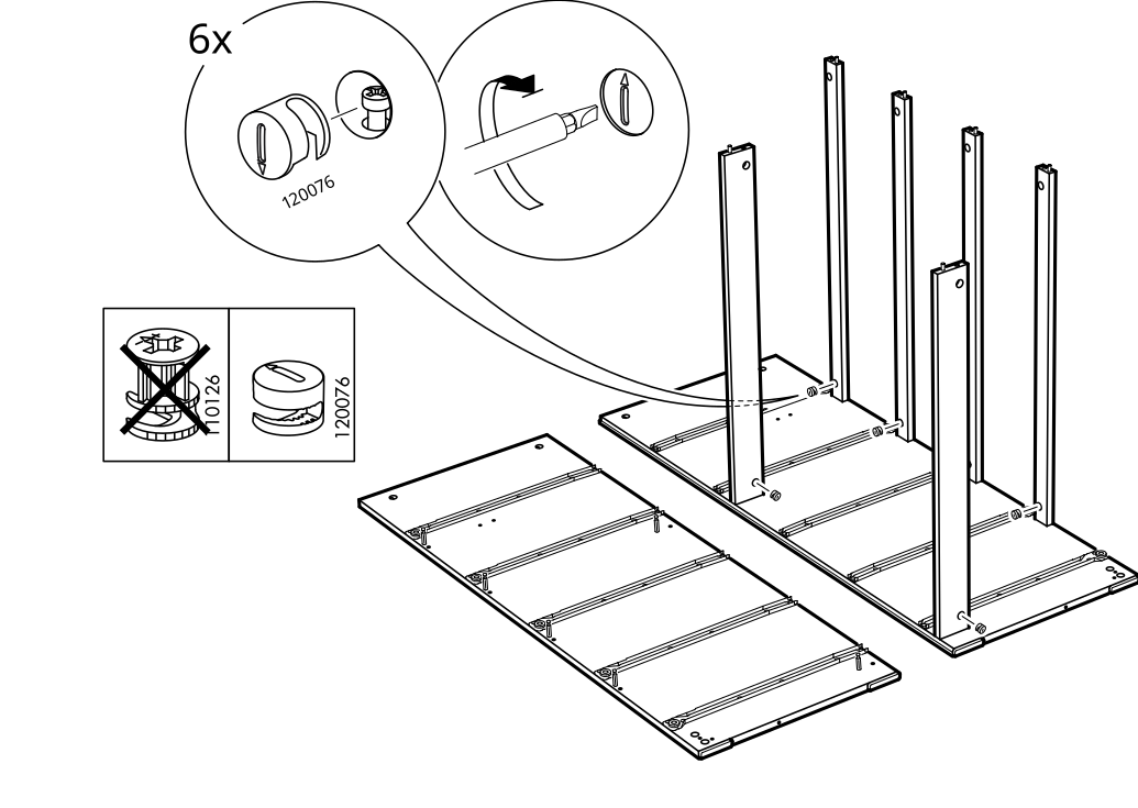
    Diagram for step 5: Install six 120076 cam locks in the indicated joints and tighten them with a screwdriver.
  6. Step 6

    Fasten the brackets to the rail using two screws of the specified type, and do not use the crossed-out screw.
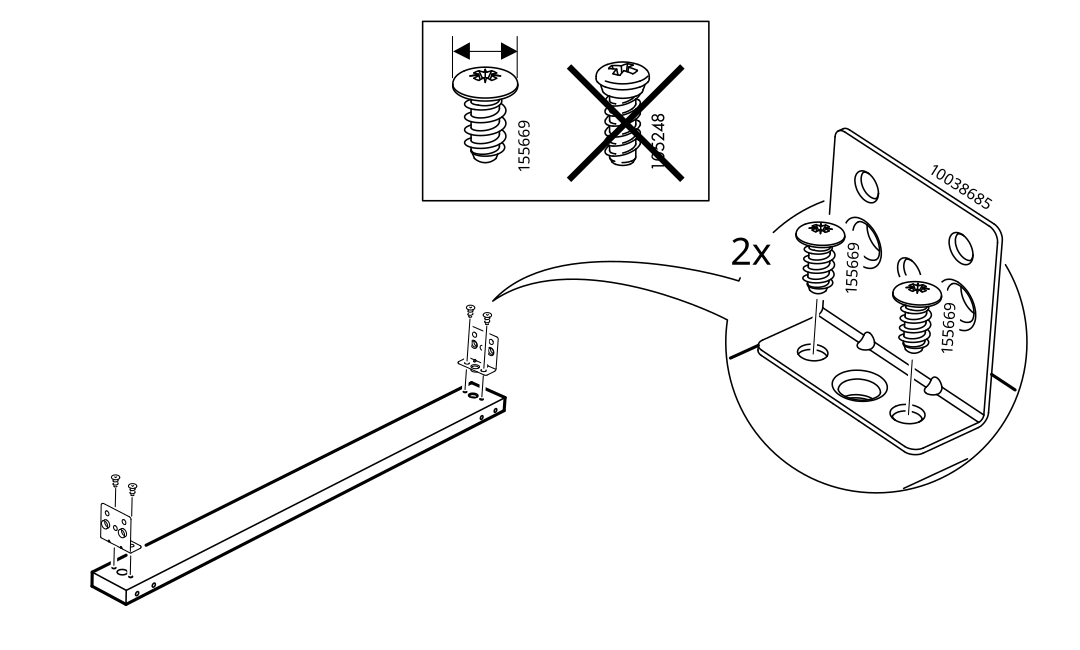
    Diagram for step 6: Fasten the brackets to the rail using two screws of the specified type, and do not use the crossed-out screw.
  7. Step 7

    Attach the second bracketed component to the rail assembly as shown, using two of the indicated parts.
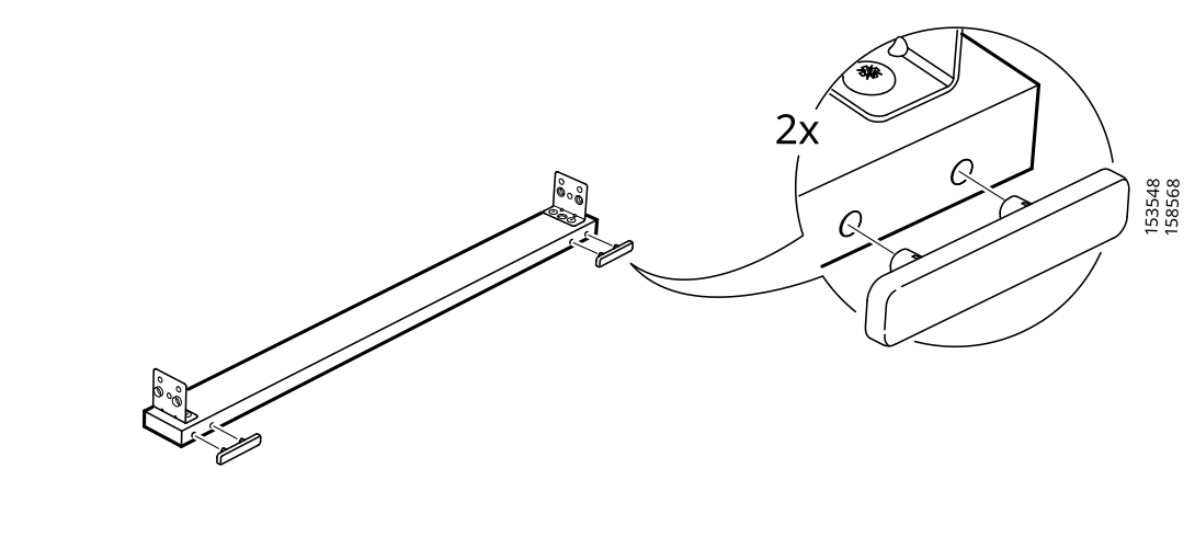
    Diagram for step 7: Attach the second bracketed component to the rail assembly as shown, using two of the indicated parts.
  8. Step 8

    Install the vertical rails and secure the corner brackets using the specified 155669 screws, oriented as shown, while avoiding the incorrect 155248 screw and incorrect bracket orientation.
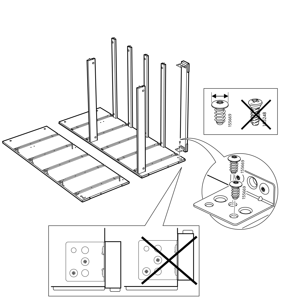
    Diagram for step 8: Install the vertical rails and secure the corner brackets using the specified 155669 screws, oriented as shown, while avoiding the incorrect 155248 screw and incorrect bracket orientation.
  9. Step 9

    Lower the top panel onto the assembled frame, aligning it with the upright supports and fittings.
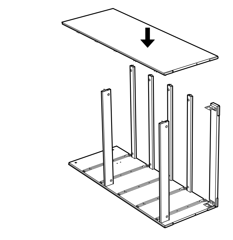
    Diagram for step 9: Lower the top panel onto the assembled frame, aligning it with the upright supports and fittings.
  10. Step 10

    Install six 120076 cam locks in the top panel and rotate them with a screwdriver to secure the top to the frame.
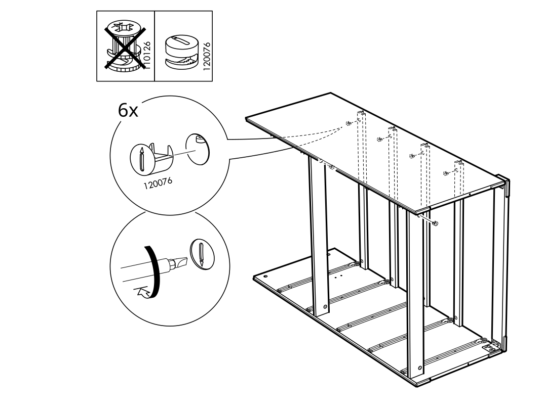
    Diagram for step 10: Install six 120076 cam locks in the top panel and rotate them with a screwdriver to secure the top to the frame.
  11. Step 11

    Fasten the tabletop assembly to the frame using the correct 155669 screws, positioned as shown, and do not use the crossed-out 155248 screw.
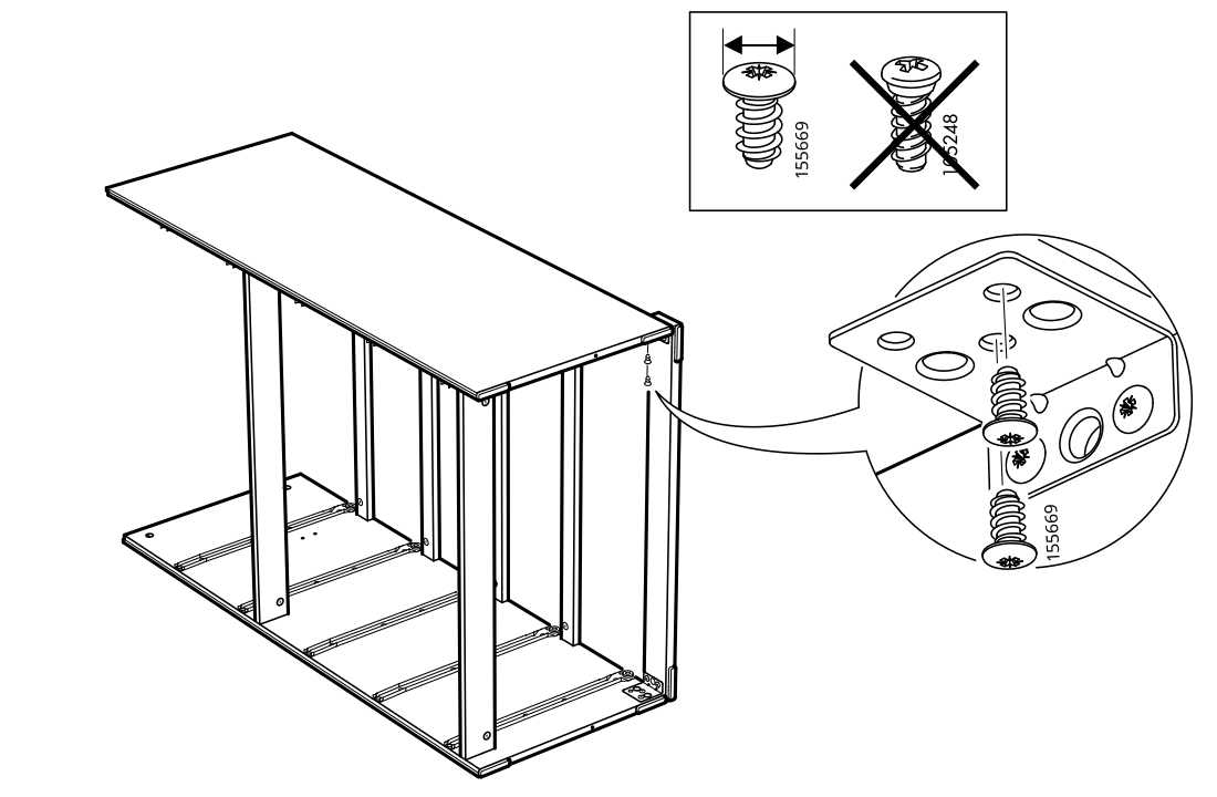
    Diagram for step 11: Fasten the tabletop assembly to the frame using the correct 155669 screws, positioned as shown, and do not use the crossed-out 155248 screw.
  12. Step 12

    Insert two 101345 dowels and six identified fasteners into the predrilled holes in the panels, using the illustrated orientation.
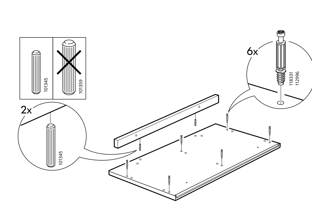
    Diagram for step 12: Insert two 101345 dowels and six identified fasteners into the predrilled holes in the panels, using the illustrated orientation.
  13. Step 13

    Attach two 102533 brackets to the panel assembly with the correctly oriented 105248 screws.
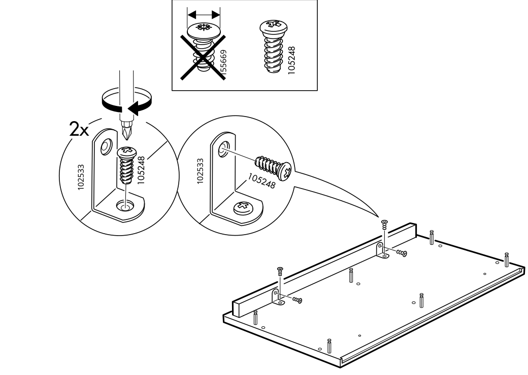
    Diagram for step 13: Attach two 102533 brackets to the panel assembly with the correctly oriented 105248 screws.
  14. Step 14

    Rotates the panel into position as indicated by the curved arrow.
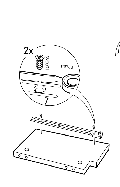
    Diagram for step 14: Rotates the panel into position as indicated by the curved arrow.
  15. Step 15

    Fastens the rail to the panel with the indicated screws and rotates the panel as shown.
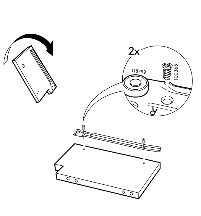
    Diagram for step 15: Fastens the rail to the panel with the indicated screws and rotates the panel as shown.
  16. Step 16

    Inserts the correct 101359 cylindrical connectors into the base panel and positions the upright panel for assembly.
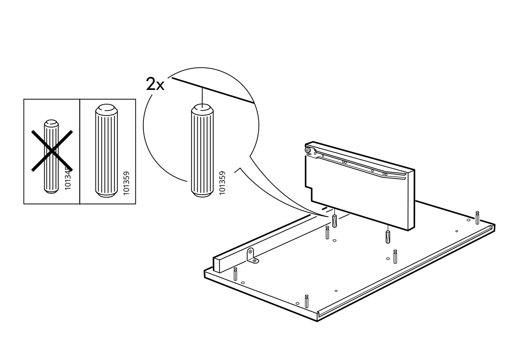
    Diagram for step 16: Inserts the correct 101359 cylindrical connectors into the base panel and positions the upright panel for assembly.
  17. Step 17

    Insert two 110126 fittings into the prepared assembly and turn them with a screwdriver as shown; do not use the crossed-out 120076 fitting.
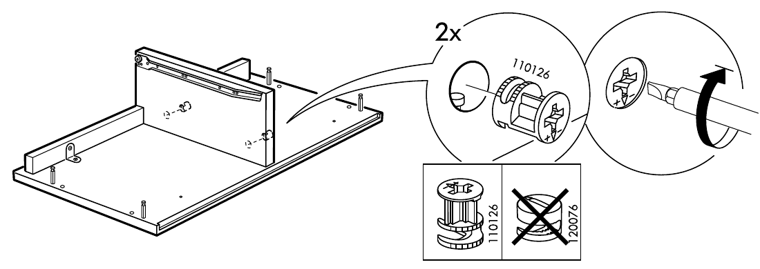
    Diagram for step 17: Insert two 110126 fittings into the prepared assembly and turn them with a screwdriver as shown; do not use the crossed-out 120076 fitting.
  18. Step 18

    Attach two 106989 brackets to the assembly using the 100823 washers and 100949 screws.
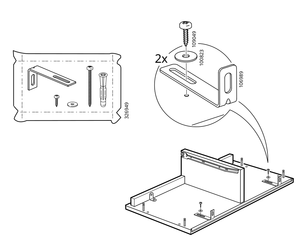
    Diagram for step 18: Attach two 106989 brackets to the assembly using the 100823 washers and 100949 screws.
  19. Step 19

    Fit the drawer runner into the cabinet and secure the two indicated sets using the printed hardware 155372 and 105248.
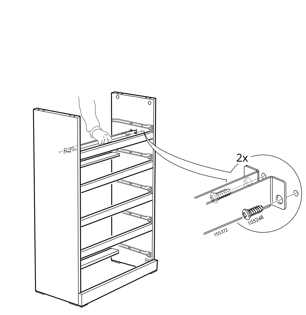
    Diagram for step 19: Fit the drawer runner into the cabinet and secure the two indicated sets using the printed hardware 155372 and 105248.
  20. Step 20

    Installs four 101345 dowels and positions the top assembly on the cabinet.
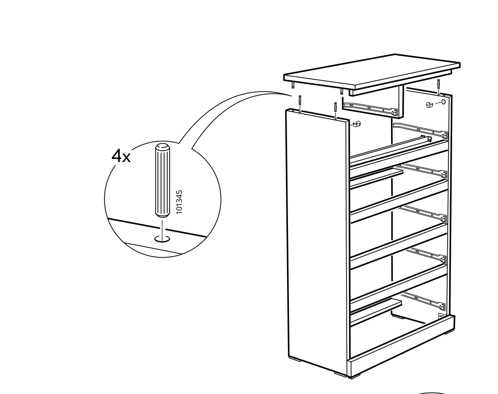
    Diagram for step 20: Installs four 101345 dowels and positions the top assembly on the cabinet.
  21. Step 21

    Secure the top panel with four 120076 cam locks, turning them with a screwdriver as shown.
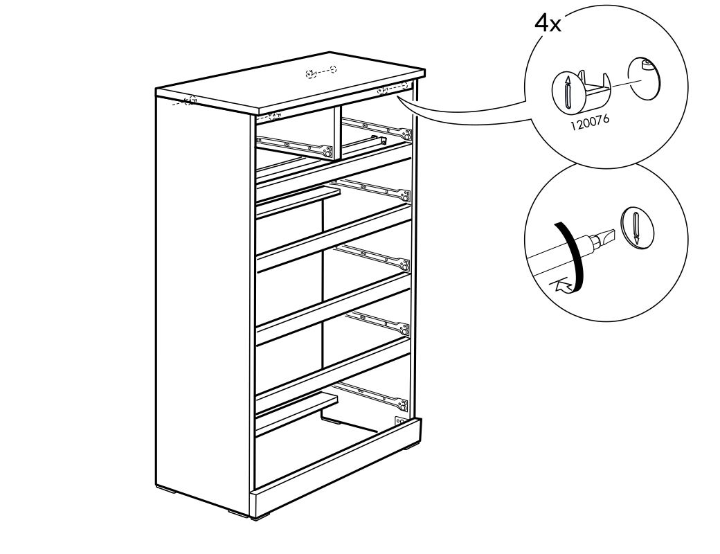
    Diagram for step 21: Secure the top panel with four 120076 cam locks, turning them with a screwdriver as shown.
  22. Step 22

    Fasten the top panel to the cabinet using the 101221 screw and a hammer.
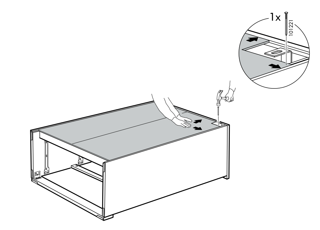
    Diagram for step 22: Fasten the top panel to the cabinet using the 101221 screw and a hammer.
  23. Step 23

    Secure the top panel to the cabinet frame with one screw while holding the panel in position.
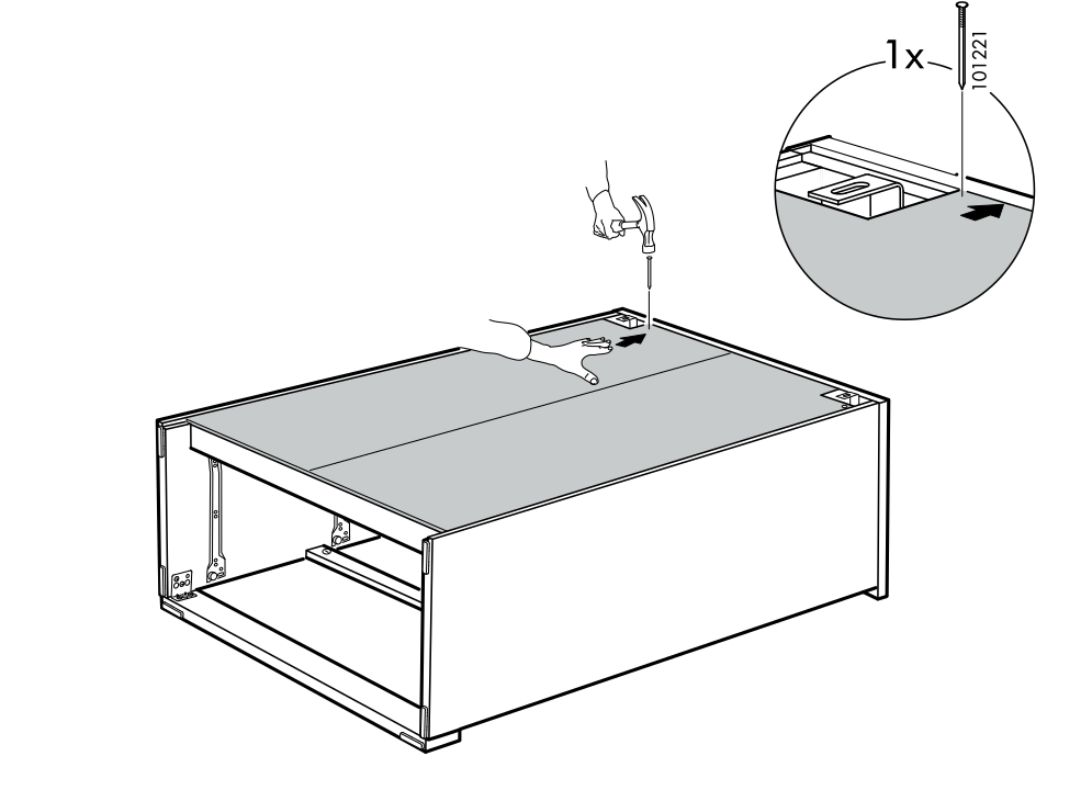
    Diagram for step 23: Secure the top panel to the cabinet frame with one screw while holding the panel in position.
  24. Step 24

    Secure the opposite side of the top panel to the cabinet frame with one screw while pressing the panel down.
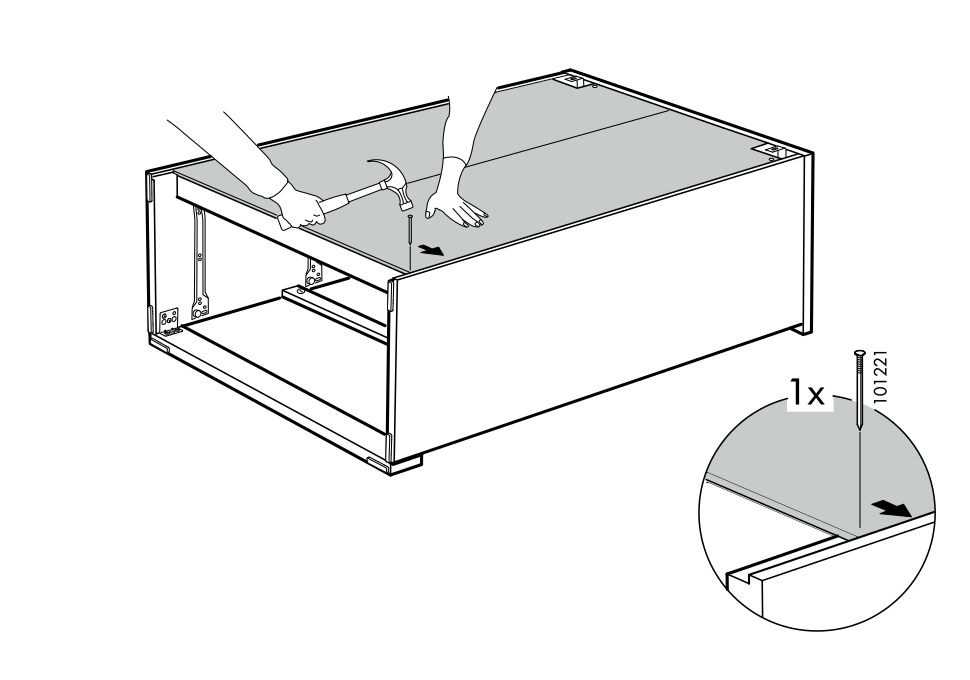
    Diagram for step 24: Secure the opposite side of the top panel to the cabinet frame with one screw while pressing the panel down.
  25. Step 25

    Use a hammer to secure the back panel to the frame with the remaining 27 nails (101221), following the positions shown in the diagram.
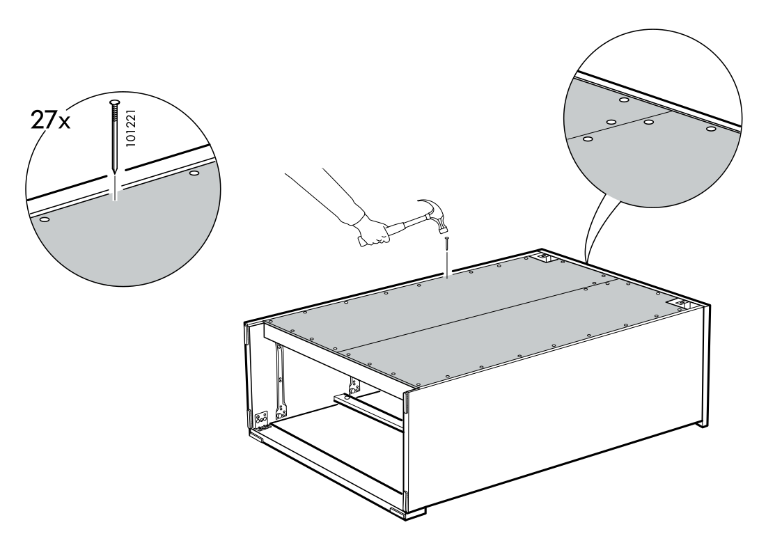
    Diagram for step 25: Use a hammer to secure the back panel to the frame with the remaining 27 nails (101221), following the positions shown in the diagram.
  26. Step 26

    Rotate the cabinet and adjust the drawer hardware at the indicated locations.
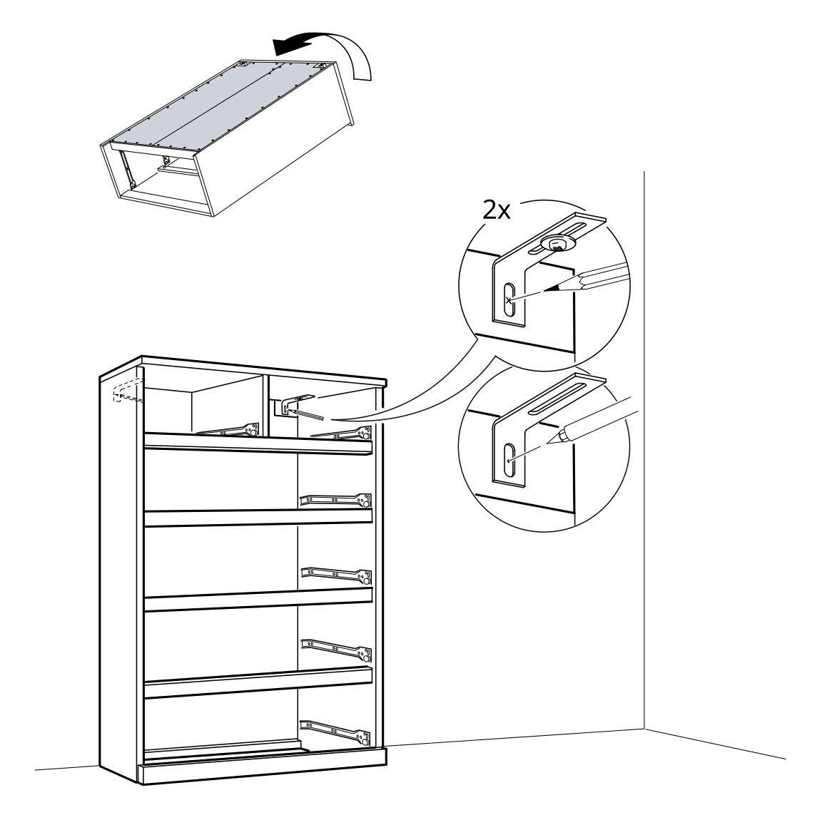
    Diagram for step 26: Rotate the cabinet and adjust the drawer hardware at the indicated locations.
  27. Step 27

    The assembled cabinet is moved to the right toward the wall.
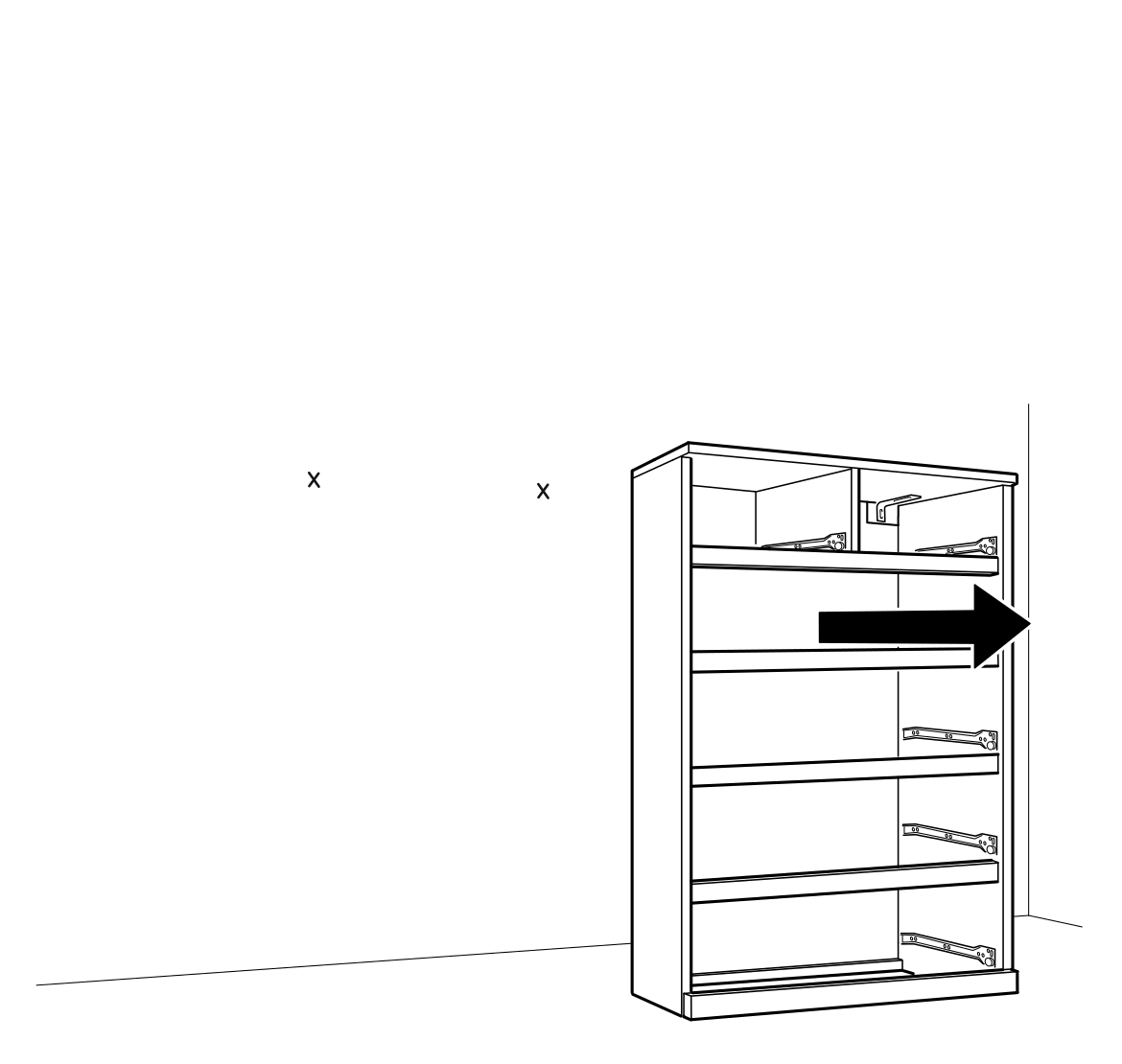
    Diagram for step 27: The assembled cabinet is moved to the right toward the wall.
  28. Safety warning

    Wall-anchoring safety reference: secure the dresser to the wall using the shown attachment method and a fixing suitable for the wall material. Before drilling, check for concealed water pipes, electrical wiring, and heating pipes and do not drill into them. For concrete use an 8 mm drill bit and drill 70 mm deep before inserting the wall plug with a hammer; for masonry use an 8 mm bit and drill approximately 30 mm before inserting the plug; for wood use a 3 mm bit and drill approximately 30 mm.
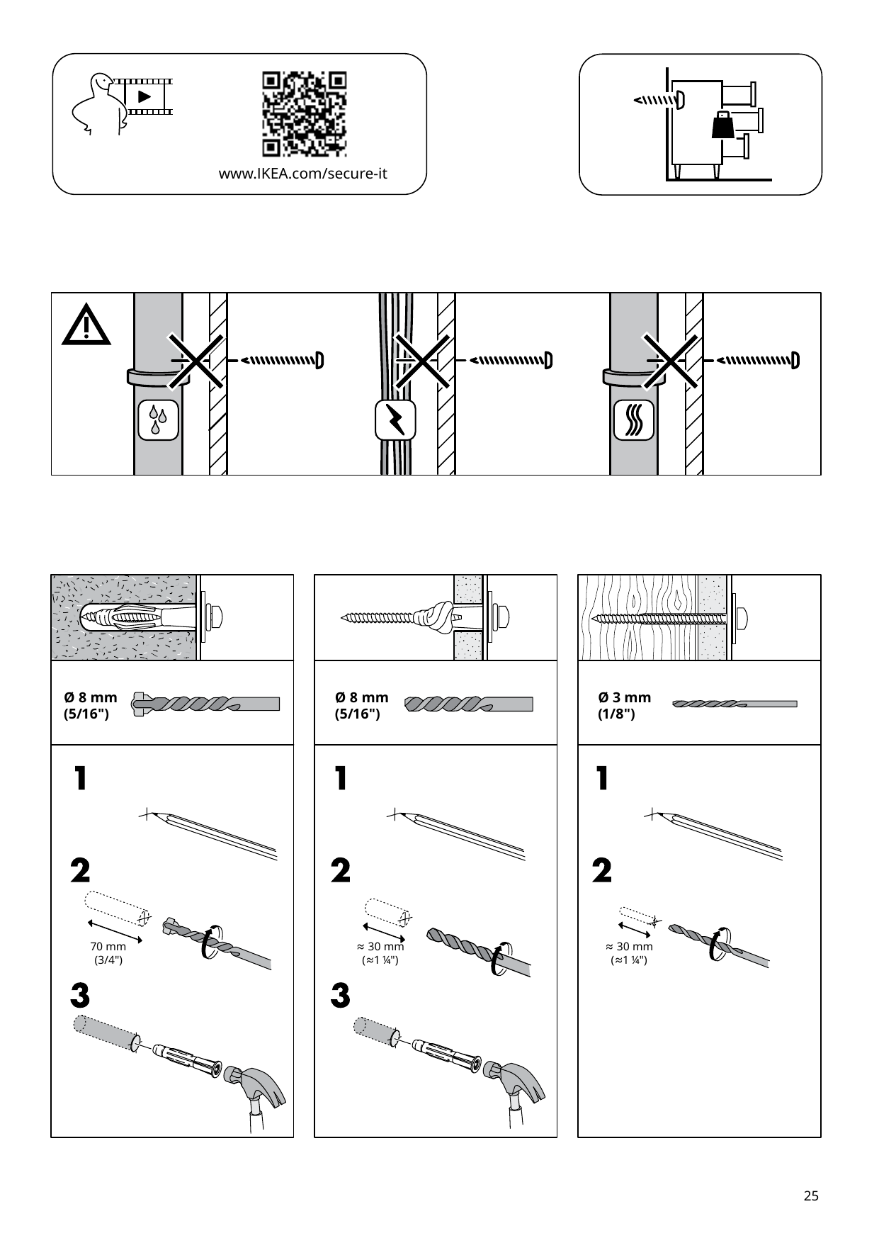
    Illustration for safety warning: Wall-anchoring safety reference: secure the dresser to the wall using the shown attachment method and a fixing suitable for the wall material. Before drilling, check for concealed water pipes, electrical wiring, and heating pipes and do not drill into them. For concrete use an 8 mm drill bit and drill 70 mm deep before inserting the wall plug with a hammer; for masonry use an 8 mm bit and drill approximately 30 mm before inserting the plug; for wood use a 3 mm bit and drill approximately 30 mm.
  29. Step 28

    Adjust the wall-attachment fittings and secure the cabinet to the wall with the shown hardware.
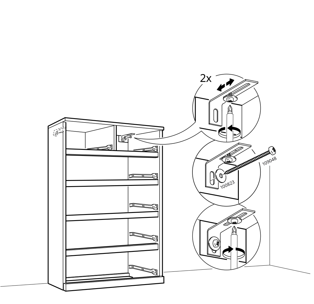
    Diagram for step 28: Adjust the wall-attachment fittings and secure the cabinet to the wall with the shown hardware.
  30. Before you begin

    Information panel showing the MALM chest of drawers and a warning against climbing, sitting, or placing weight on the drawers.
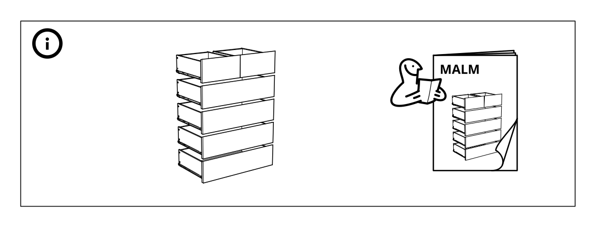
    Illustration for assembly note: Information panel showing the MALM chest of drawers and a warning against climbing, sitting, or placing weight on the drawers.
  31. Step 29

    Adjusts or inserts the upper drawer into the cabinet runners while observing the anti-tip warning.
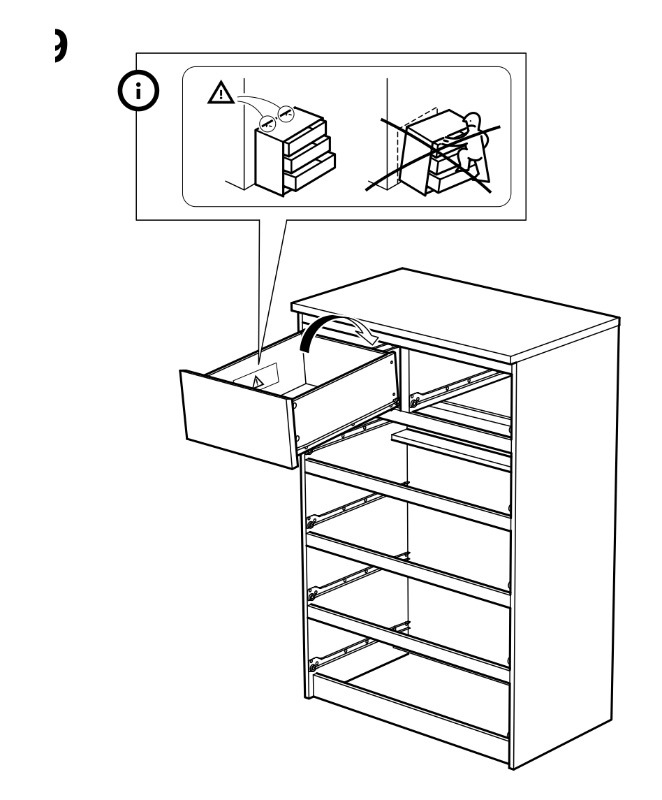
    Diagram for step 29: Adjusts or inserts the upper drawer into the cabinet runners while observing the anti-tip warning.

MALM 6-drawer dresser drawers

  1. Step 1

    The builder selects the shown drawer configuration, inserts and tightens eight 118331 fasteners into the panel, and repeats the placement shown for the selected configuration.

    Diagram for step 1: The builder selects the shown drawer configuration, inserts and tightens eight 118331 fasteners into the panel, and repeats the placement shown for the selected configuration.
  2. Before you begin

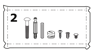
    A dashed hardware-bag illustration labeled 2 contains several types of assembly hardware used for the construction.

    Illustration for assembly note: A dashed hardware-bag illustration labeled 2 contains several types of assembly hardware used for the construction.
  3. Step 2

    Insert the cylindrical fasteners into the base and attach the upright panels as shown, observing the anti-tip warning.

    Diagram for step 2: Insert the cylindrical fasteners into the base and attach the upright panels as shown, observing the anti-tip warning.
  4. Step 3

    Install and tighten eight 120076 fasteners in the assembled base components, following the detail illustrations.

    Diagram for step 3: Install and tighten eight 120076 fasteners in the assembled base components, following the detail illustrations.
  5. Step 4

    Lower the large panel vertically into the assembled base and side components.

    Diagram for step 4: Lower the large panel vertically into the assembled base and side components.
  6. Step 5

    The top panel is positioned and joined to the assembled cabinet frame in the indicated orientation.

    Diagram for step 5: The top panel is positioned and joined to the assembled cabinet frame in the indicated orientation.
  7. Step 6

    Eight screws are driven into the cabinet assembly using a hammer as shown.

    Diagram for step 6: Eight screws are driven into the cabinet assembly using a hammer as shown.
  8. Step 7

    Fasten the cabinet assembly with four screws, as shown in the enlarged detail, and continue with the resulting cabinet configuration.

    Diagram for step 7: Fasten the cabinet assembly with four screws, as shown in the enlarged detail, and continue with the resulting cabinet configuration.
  9. Step 8

    Install the roller hardware and associated rails onto the cabinet assembly, using the indicated screws and pressing the components into place.

    Diagram for step 8: Install the roller hardware and associated rails onto the cabinet assembly, using the indicated screws and pressing the components into place.
  10. Safety warning

    Shows the correct drawer arrangement with the drawers aligned in the unit, contrasted with an incorrect arrangement marked with a large X.

    Illustration for safety warning: Shows the correct drawer arrangement with the drawers aligned in the unit, contrasted with an incorrect arrangement marked with a large X.
  11. Step 9

    The installer fastens the drawer component, inserts and rotates the fitting, tightens it with a screwdriver, and secures it with screw 105344.

    Diagram for step 9: The installer fastens the drawer component, inserts and rotates the fitting, tightens it with a screwdriver, and secures it with screw 105344.

Make it yours

Small additions. A better setup.

These optional additions are separate from any parts, safety equipment, or tools required to assemble the product.

Explore add-ons

Some links are affiliate links. We may earn a commission if you buy through them, at no extra cost to you. As an Amazon Associate, we earn from qualifying purchases.

  • madesmart 5-compartment tray, white

    A shallow tray organizes pens, cables, and small items in a MALM drawer.

    The 12.75 × 9 × 1.88 in tray fits the listed 32 × 43 cm top drawer and the larger drawers. Turn the 32.39 cm side along the 43 cm depth; confirm usable clearance before buying.

    View product
  • IKEA SKUBB drawer organizer set, white (6 pieces)

    Six soft organizers sort smaller items in the MALM dresser drawers.

    IKEA lists the SKUBB 6-piece set as an accessory for this exact 80 cm MALM dresser. Check each insert against your drawer and do not force it.

    View product
  • Simple Houseware foldable drawer organizers, gray (4-pack)

    Soft bins separate socks, accessories, and small clothing across MALM drawers.

    The small bins are 29.85 × 14.61 × 8.89 cm; square bins are 30.48 cm per side and 8.89 cm high. These fit the listed 32 × 43 cm and 72 × 43 cm drawer footprints with 16 cm height. Check usable clearance first.

    View product

Video guide

Dimensions

Width

31 1/2"

Depth

19"

Height

48 3/8"