How to assemble IKEA MALM bed frame

MALM bed frame, dark-brown veneer, Queen

This guide covers the IKEA MALM Queen bed frame in dark-brown veneer, combination 095.743.67. Use the bed-frame instructions and available videos, checking the diagrams as you assemble.

View on IKEA
MALM bed frame

Interactive assembly guide

Step-by-Step Instructions

1 different parts, 1 boxes total — click on a package to see step-by-step assembly instructions

MALM Bed frame

005.994.52

x1

30 ½ "

Width

3 ½ "

Height

67 ¼ "

Length

49 lb 3 oz

Weight

Start Assembly

Written guide

Step-by-step instructions with diagrams

Follow the numbered assembly steps below, or open the interactive guide above to track progress and zoom into each diagram. This guide includes 15 illustrated steps.

MALM Bed frame

  1. Before you begin

    Preparation and safety guidance panels show using a screwdriver and hammer, avoiding solo assembly and unsafe handling, avoiding assembly on hard surfaces, and contacting IKEA support if unsure.
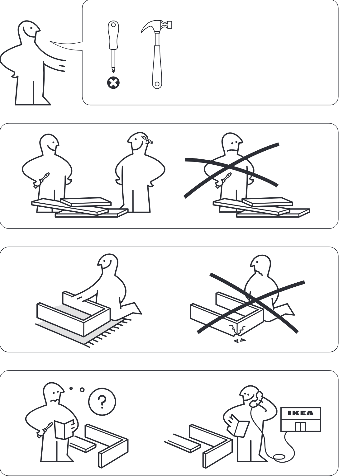
    Illustration for assembly note: Preparation and safety guidance panels show using a screwdriver and hammer, avoiding solo assembly and unsafe handling, avoiding assembly on hard surfaces, and contacting IKEA support if unsure.
  2. Step 1

    Place the two side panels on a soft surface and align the top panel above them, then clip six 122628 edge pieces onto the panel edge using the hammer as shown in the zoom callout.
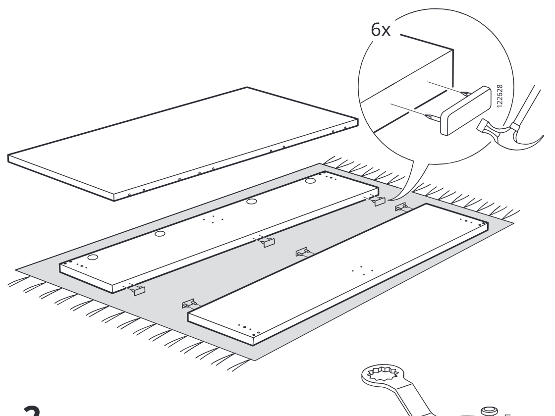
    Diagram for step 1: Place the two side panels on a soft surface and align the top panel above them, then clip six 122628 edge pieces onto the panel edge using the hammer as shown in the zoom callout.
  3. Step 2

    Insert and tighten eight 123491 cam screws into the predrilled holes of the two long panels with tool 113453, following the correct insertion depth shown in the inline do/don’t boxes.
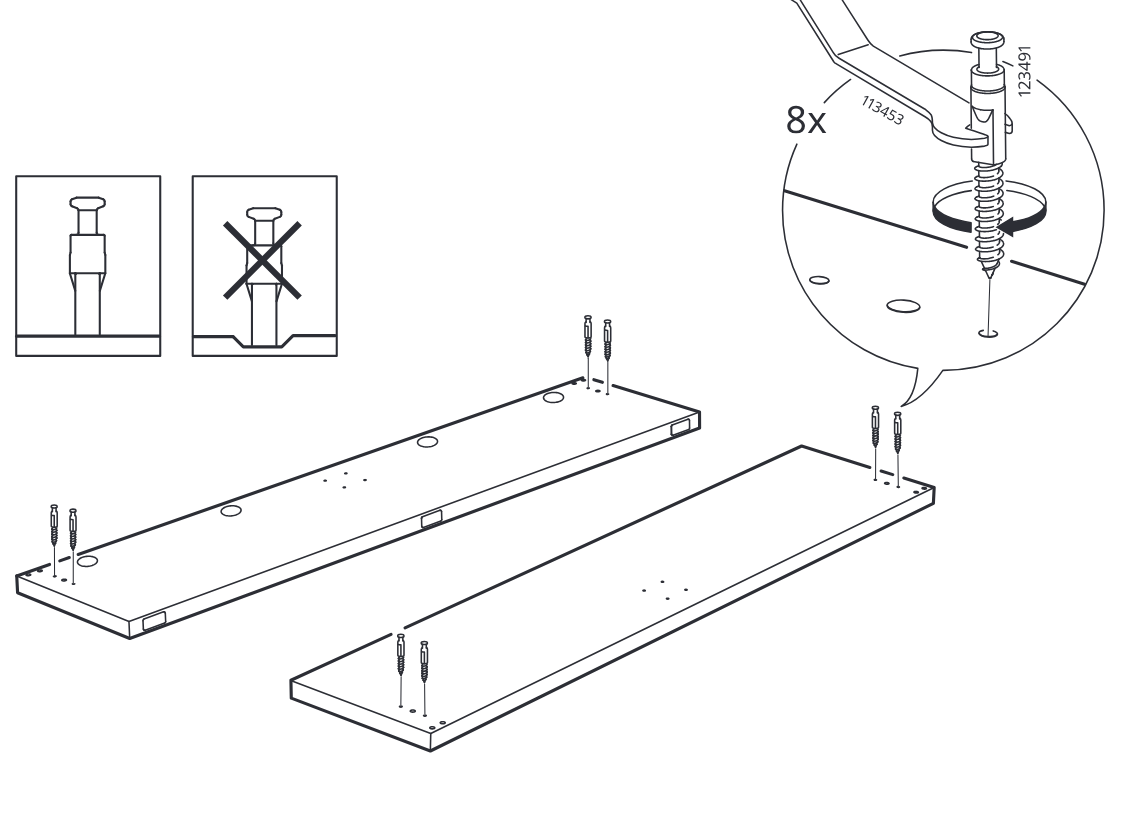
    Diagram for step 2: Insert and tighten eight 123491 cam screws into the predrilled holes of the two long panels with tool 113453, following the correct insertion depth shown in the inline do/don’t boxes.
  4. Step 3

    Insert four 101359 dowels into the side rail ends and align the rails between the two end panels, noting that 101367 is not used.
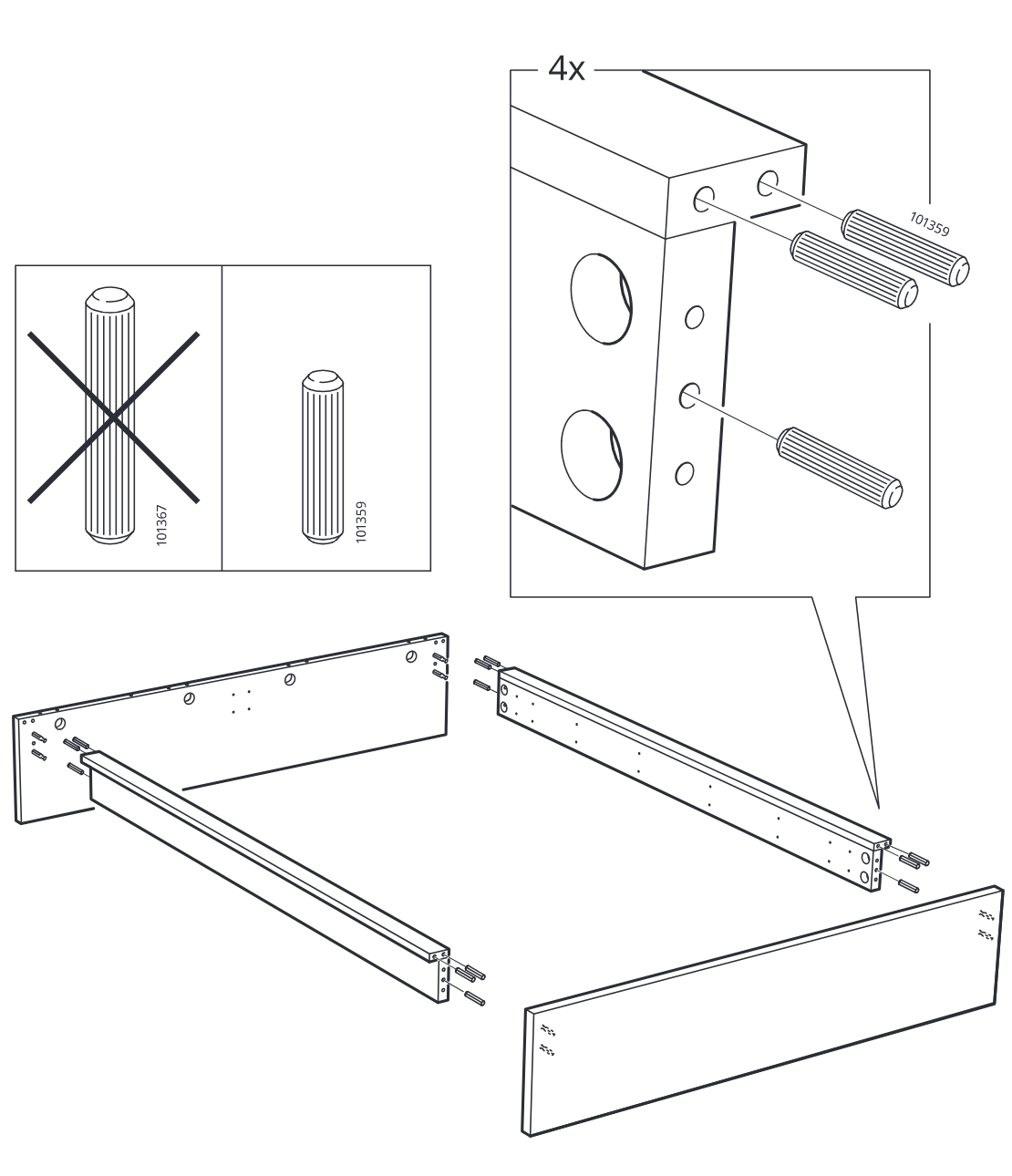
    Diagram for step 3: Insert four 101359 dowels into the side rail ends and align the rails between the two end panels, noting that 101367 is not used.
  5. Step 4

    The side panel is pushed onto the dowels and cam fittings, then the cams are tightened with the Allen key as shown in the four close-up sequence panels.
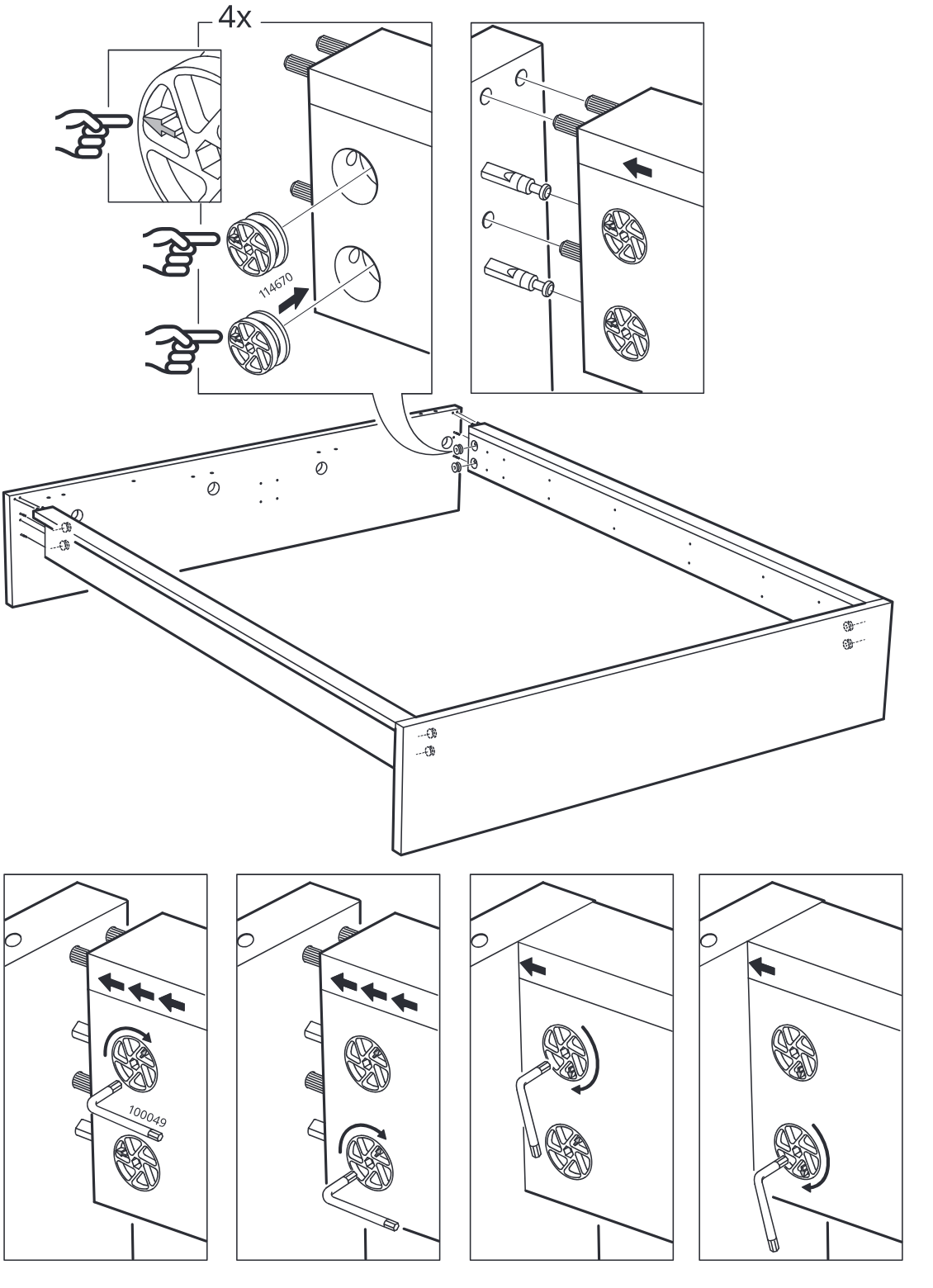
    Diagram for step 4: The side panel is pushed onto the dowels and cam fittings, then the cams are tightened with the Allen key as shown in the four close-up sequence panels.
  6. Step 5

    Insert five ribbed dowels into the top holes along the side frame, as indicated by the zoom detail of part 101367.
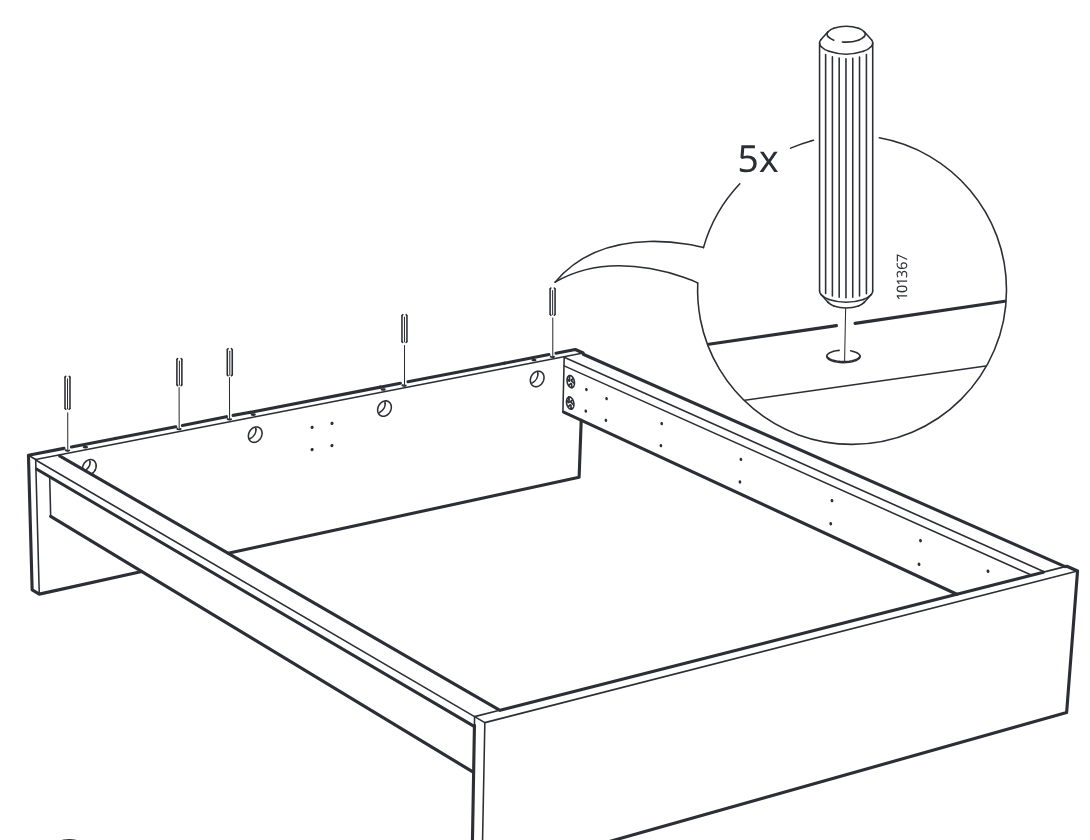
    Diagram for step 5: Insert five ribbed dowels into the top holes along the side frame, as indicated by the zoom detail of part 101367.
  7. Step 6

    Position the panel onto the table edge and screw in four connector bolts while rotating with the tool, following the correct insertion depth shown in the two comparison boxes.
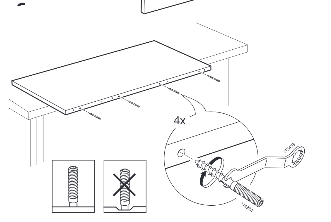
    Diagram for step 6: Position the panel onto the table edge and screw in four connector bolts while rotating with the tool, following the correct insertion depth shown in the two comparison boxes.
  8. Step 7

    The headboard panel is lowered onto four cam bolts on the bed frame, then the four cam locks are tightened with the included wrench as shown in the zoom callouts.
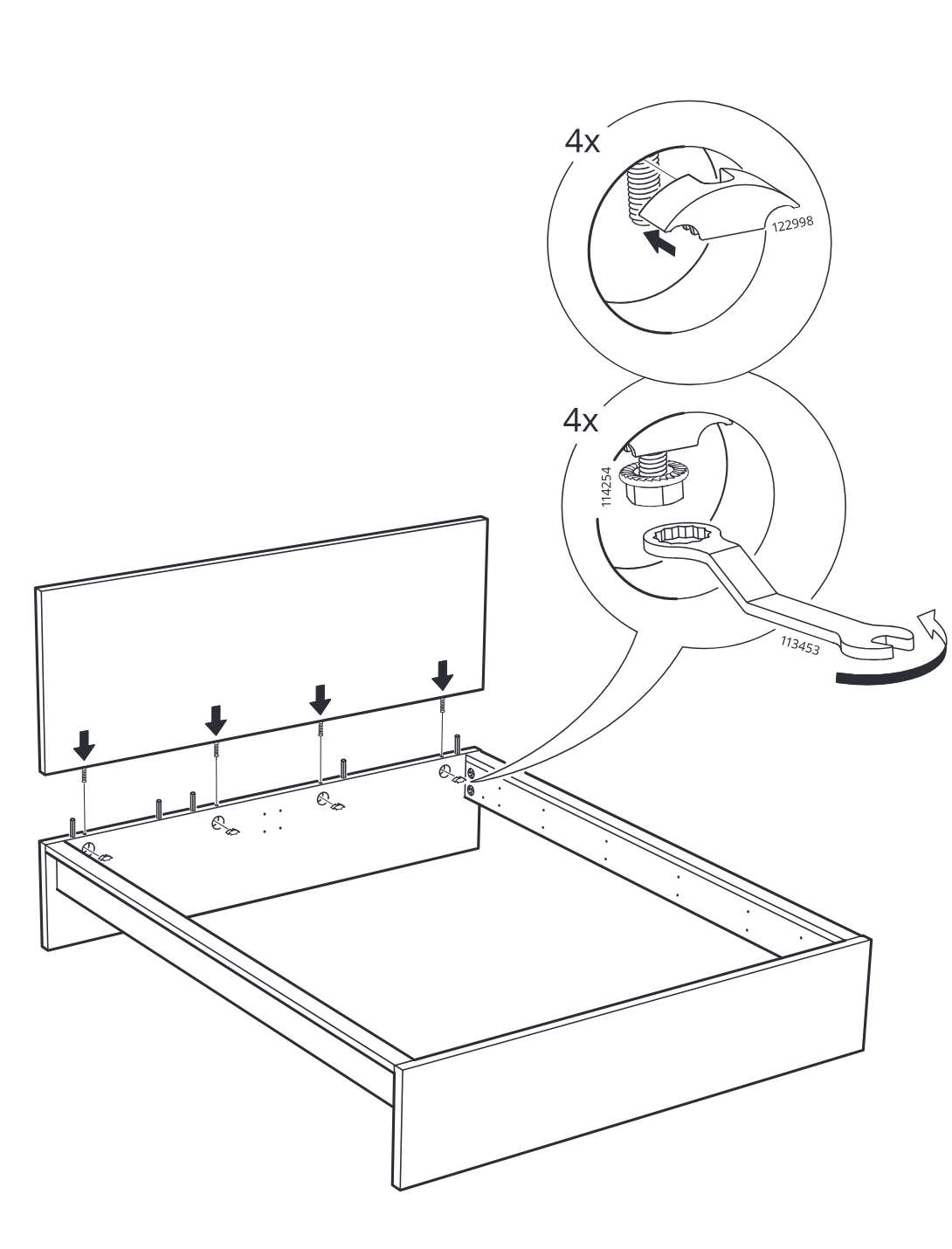
    Diagram for step 7: The headboard panel is lowered onto four cam bolts on the bed frame, then the four cam locks are tightened with the included wrench as shown in the zoom callouts.
  9. Before you begin

    Circled information panel for step 8 shows two bed-side configurations and where to position/attach side rail hardware using parts 114290/114291.
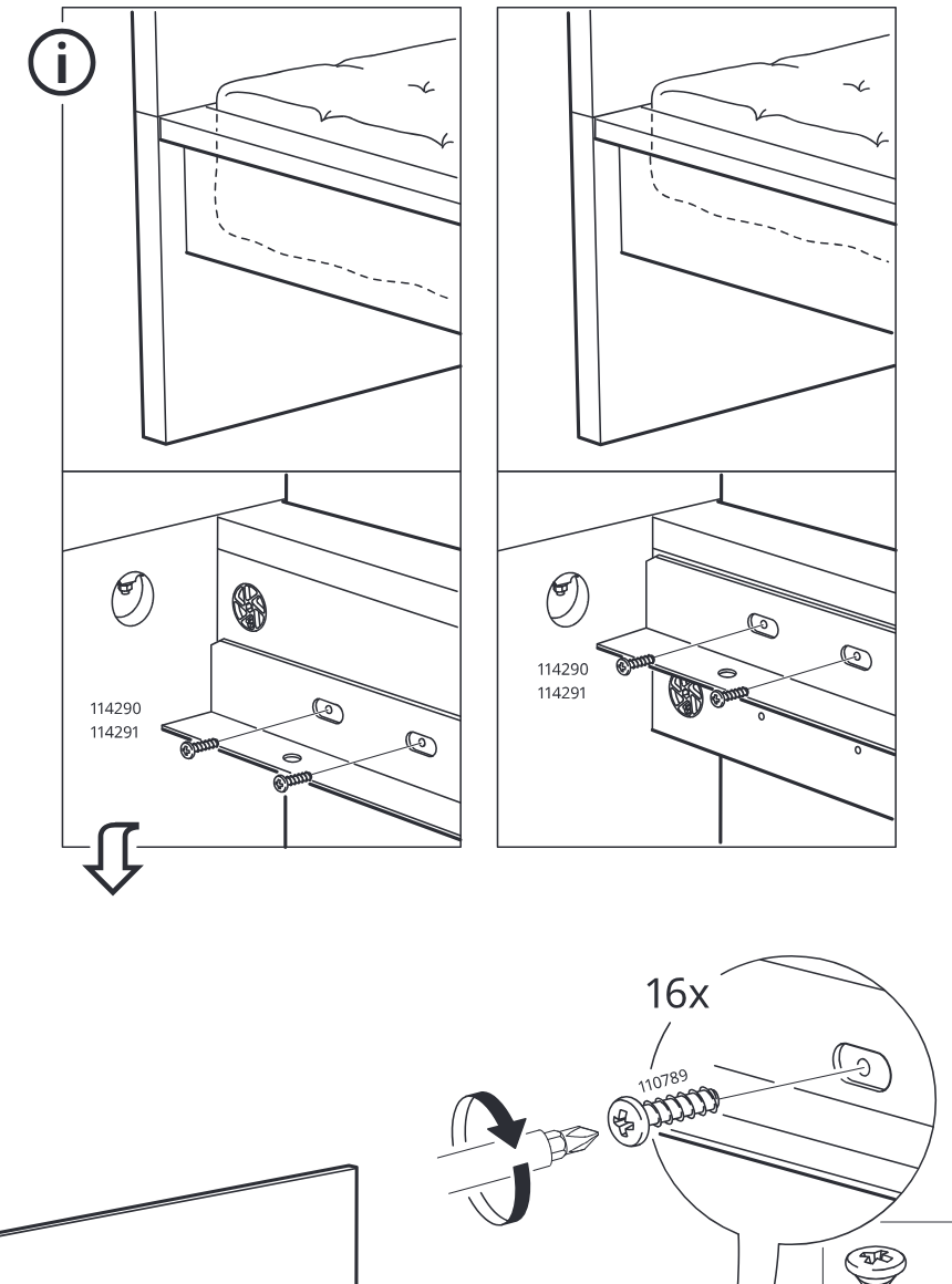
    Illustration for assembly note: Circled information panel for step 8 shows two bed-side configurations and where to position/attach side rail hardware using parts 114290/114291.
  10. Step 8

    Screw part 110789 into the side rail inserts along the frame using a screwdriver (16 total), as shown by the zoom callout and screw-type comparison box.
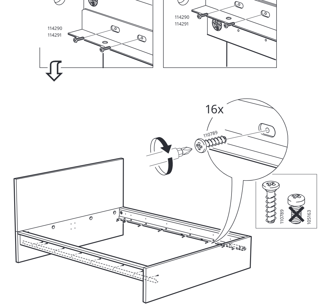
    Diagram for step 8: Screw part 110789 into the side rail inserts along the frame using a screwdriver (16 total), as shown by the zoom callout and screw-type comparison box.
  11. Step 9

    Attach the 116791 metal bracket to the inside panel using two 110789 screws in each position shown, ensuring the screw type is correct and repeating the fastening in both marked locations.
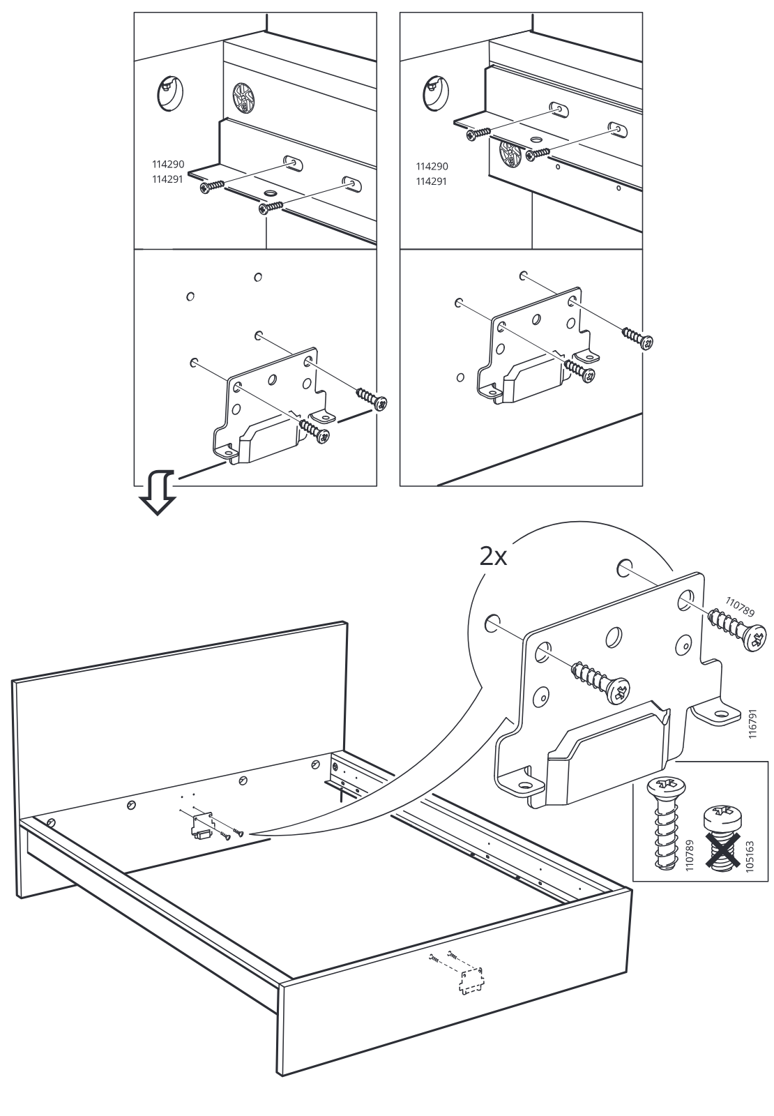
    Diagram for step 9: Attach the 116791 metal bracket to the inside panel using two 110789 screws in each position shown, ensuring the screw type is correct and repeating the fastening in both marked locations.
  12. Step 10

    Attach and secure the long rail and inner supports to the bed frame using four screws 117327, as shown in the two zoomed callouts.
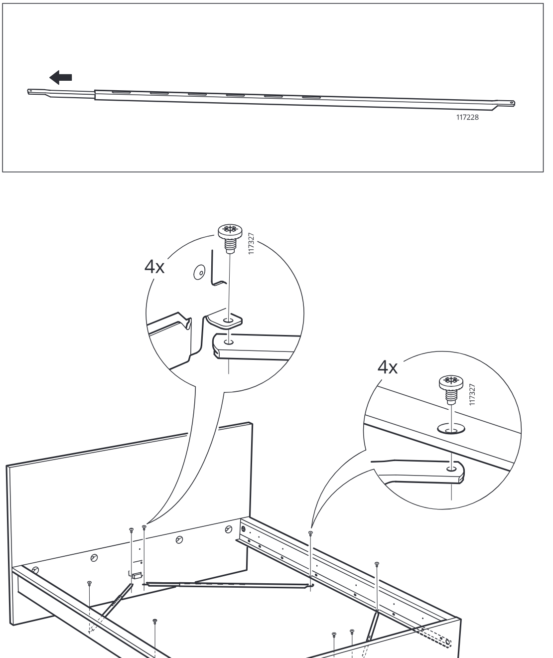
    Diagram for step 10: Attach and secure the long rail and inner supports to the bed frame using four screws 117327, as shown in the two zoomed callouts.
  13. Step 11

    The frame is squared and the cross-bracing is fixed with four screws (117327), as indicated by the zoomed screw detail.
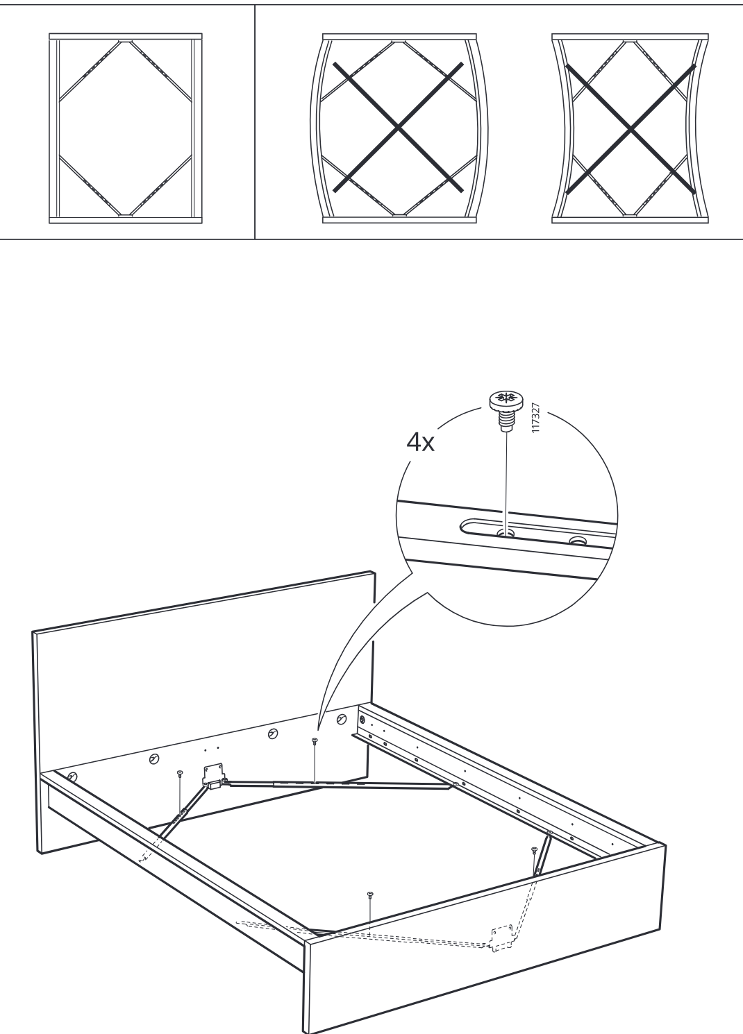
    Diagram for step 11: The frame is squared and the cross-bracing is fixed with four screws (117327), as indicated by the zoomed screw detail.
  14. Before you begin

    Information panel shows extending the rail segment in the correct direction by hand.
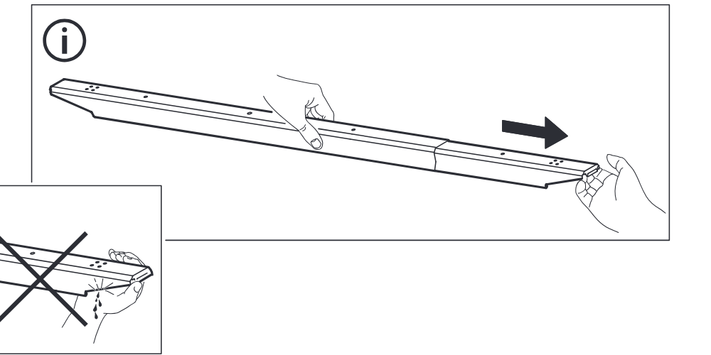
    Illustration for assembly note: Information panel shows extending the rail segment in the correct direction by hand.
  15. Step 12

    The extended rail is positioned onto the bed frame and lowered into place while alignment arrows indicate where it slides and seats.
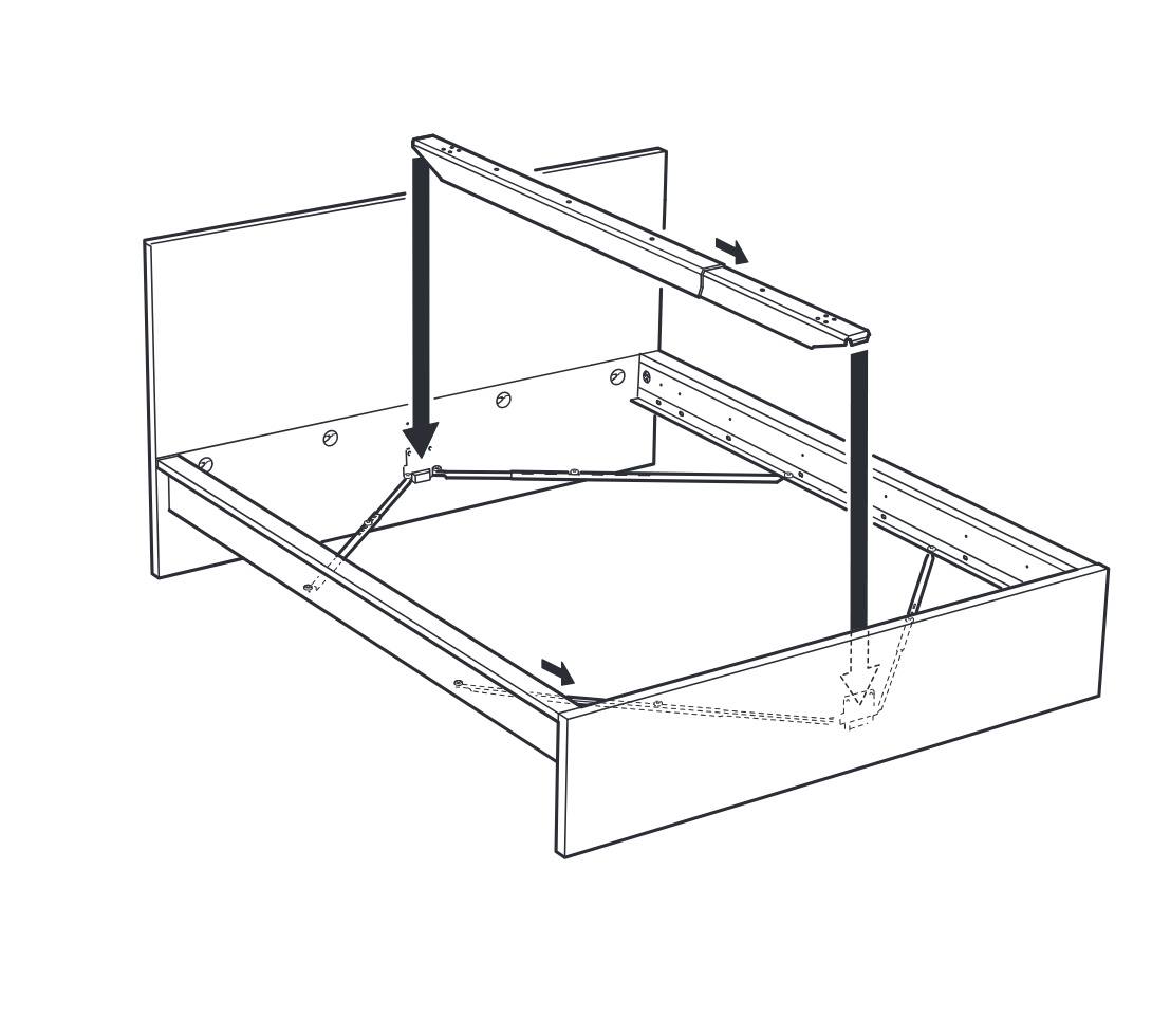
    Diagram for step 12: The extended rail is positioned onto the bed frame and lowered into place while alignment arrows indicate where it slides and seats.
  16. Before you begin

    Information panel shows two slat-base variants and indicates to continue according to the matching bed base type.
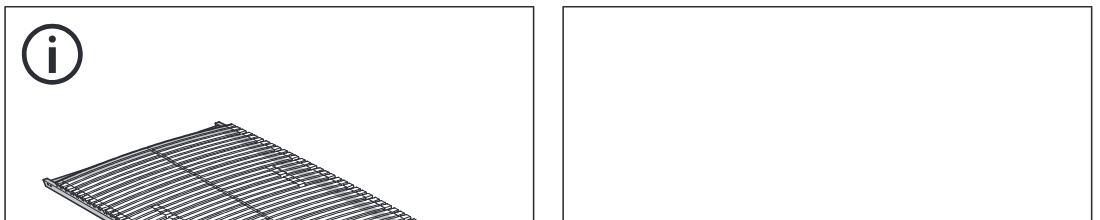
    Illustration for assembly note: Information panel shows two slat-base variants and indicates to continue according to the matching bed base type.
  17. Step 15

    The slatted base is lowered into the bed frame and secured with eight 105163 clips, with close-up circles showing the correct clip placement.
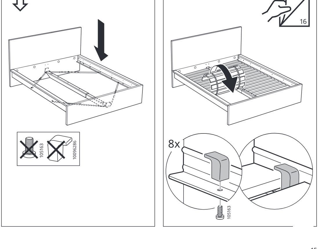
    Diagram for step 15: The slatted base is lowered into the bed frame and secured with eight 105163 clips, with close-up circles showing the correct clip placement.
  18. Step 13

    The frame is assembled with side and front panels while eight clips (10096286) are fastened with screws (1005163), and four clips are then pressed into place on each side as shown in the two info callouts.
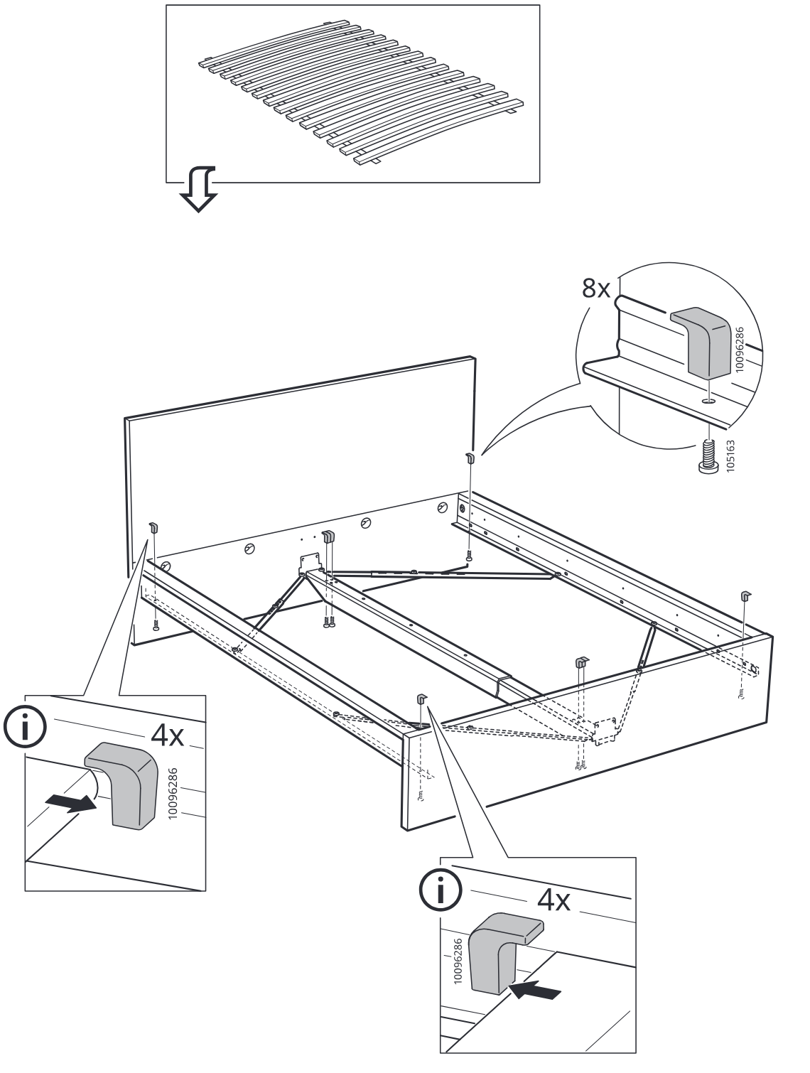
    Diagram for step 13: The frame is assembled with side and front panels while eight clips (10096286) are fastened with screws (1005163), and four clips are then pressed into place on each side as shown in the two info callouts.
  19. Step 14

    The slatted base section is rotated and positioned into the bed frame, and four corner clips are pushed into place as shown in the two zoom callouts.
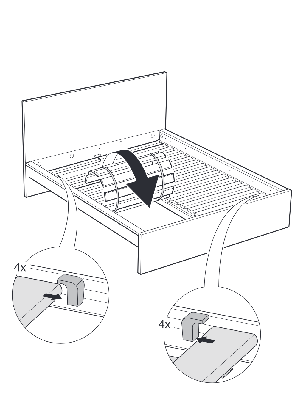
    Diagram for step 14: The slatted base section is rotated and positioned into the bed frame, and four corner clips are pushed into place as shown in the two zoom callouts.
  20. Before you begin

    Information panel indicates to follow the separate MALM drawer manual while showing the bed frame with drawer components.
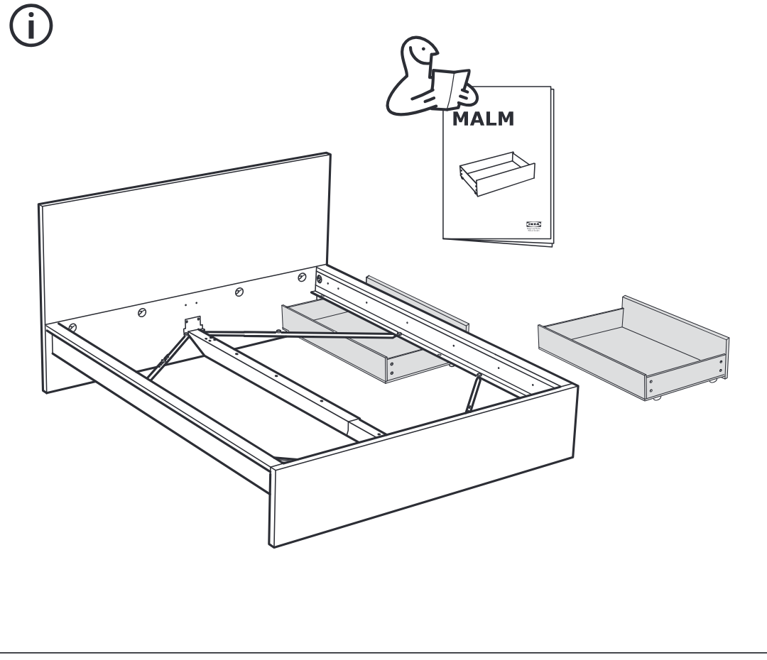
    Illustration for assembly note: Information panel indicates to follow the separate MALM drawer manual while showing the bed frame with drawer components.

Video guide