How to assemble IKEA NORDLI bed with headboard and storage

NORDLI bed with headboard and storage, white, Queen

This guide covers the white IKEA NORDLI Queen bed with headboard and storage, combination 692.414.22. Choose the storage bed-frame or headboard diagrams; video is available for the bed-frame section.

View on IKEA
NORDLI bed with headboard and storage

Interactive assembly guide

Step-by-Step Instructions

2 different parts, 2 boxes total — click on a package to see step-by-step assembly instructions

NORDLI Bed frame with storage

003.498.49

x1

30 ¾ "

Width

2 ¼ "

Height

31 ¾ "

Length

49 lb 4 oz

Weight

Start Assembly

NORDLI Headboard

103.729.76

x1

11 "

Width

4 ¼ "

Height

61 "

Length

38 lb 13 oz

Weight

Start Assembly

Written guide

Step-by-step instructions with diagrams

Follow the numbered assembly steps below, or open the interactive guide above to track progress and zoom into each diagram. This guide includes 23 illustrated steps.

NORDLI Bed frame with storage

  1. Before you begin

    Preparation and safety guidance panels show required tools, proper protected work surface use, and contacting IKEA support if assembly is unclear.
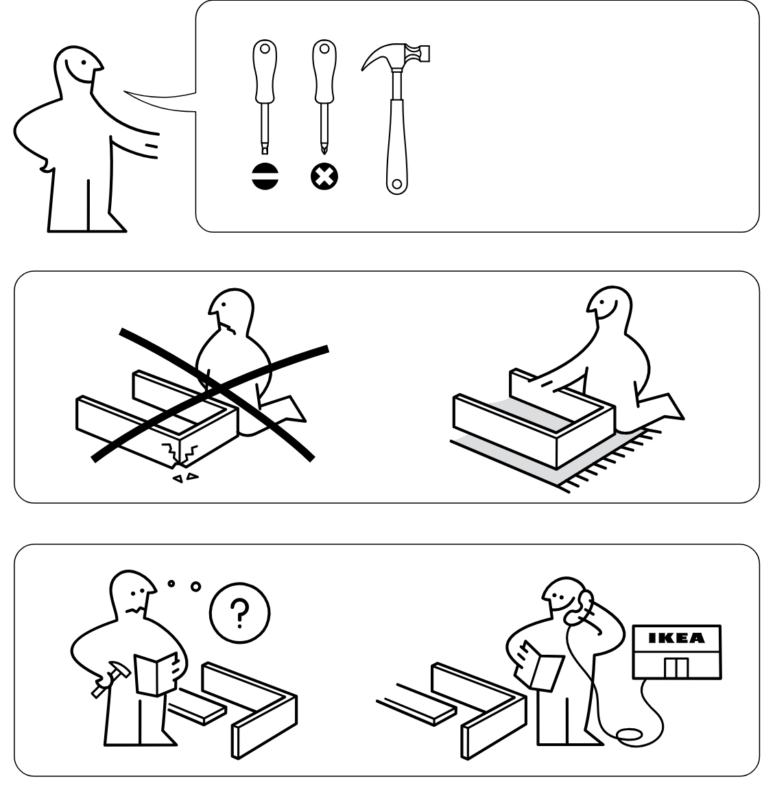
    Illustration for assembly note: Preparation and safety guidance panels show required tools, proper protected work surface use, and contacting IKEA support if assembly is unclear.
  2. Before you begin

    Parts-bag reference for step 1 shows the required fittings and demonstrates correct screw-in orientation of cam bolts (part 118331), including a 4x quantity callout and a do/don't comparison panel.
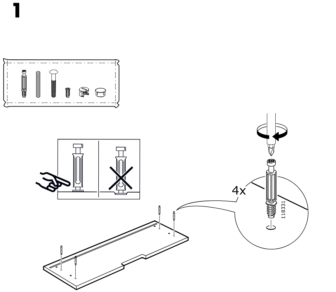
    Illustration for assembly note: Parts-bag reference for step 1 shows the required fittings and demonstrates correct screw-in orientation of cam bolts (part 118331), including a 4x quantity callout and a do/don't comparison panel.
  3. Step 2

    Insert four wooden dowels (101372) into the edge holes of the two long panels as shown in the zoom callout.
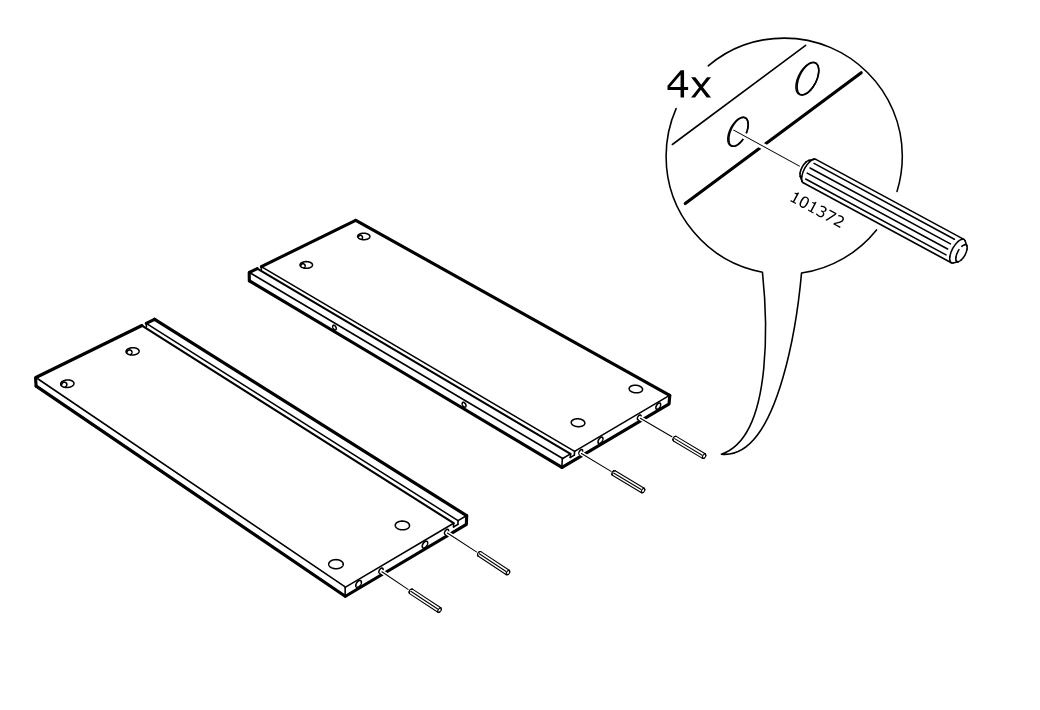
    Diagram for step 2: Insert four wooden dowels (101372) into the edge holes of the two long panels as shown in the zoom callout.
  4. Step 3

    Place the two side panels upright onto the base panel, aligning and lowering them onto the pre-positioned pins/dowels.
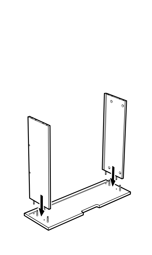
    Diagram for step 3: Place the two side panels upright onto the base panel, aligning and lowering them onto the pre-positioned pins/dowels.
  5. Step 4

    Insert and turn four cam locks (119030) with a screwdriver to secure the side panels to the base.
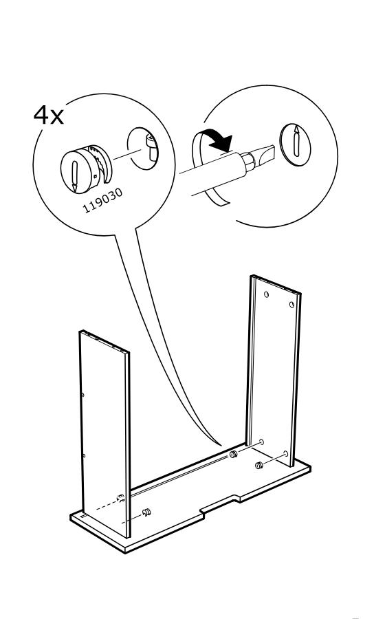
    Diagram for step 4: Insert and turn four cam locks (119030) with a screwdriver to secure the side panels to the base.
  6. Step 5

    The back panel is lowered vertically into the grooves between the two side panels on the base assembly.
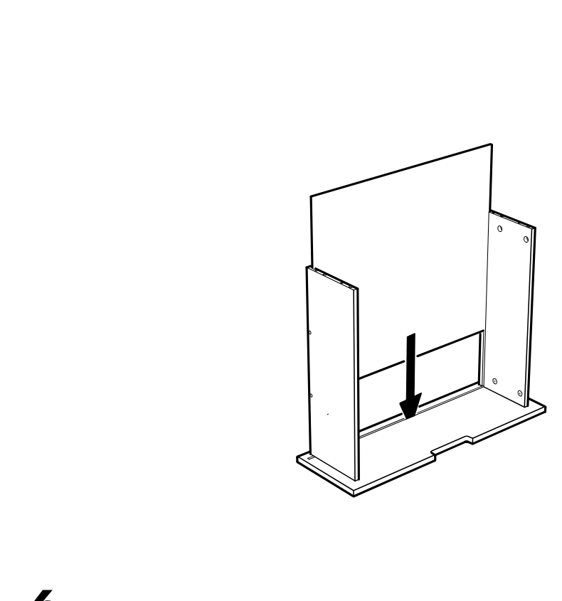
    Diagram for step 5: The back panel is lowered vertically into the grooves between the two side panels on the base assembly.
  7. Step 6

    The top panel is positioned above the side panels and lowered downward to close the cabinet frame.
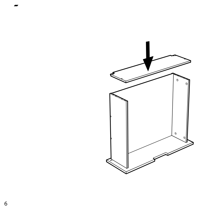
    Diagram for step 6: The top panel is positioned above the side panels and lowered downward to close the cabinet frame.
  8. Step 7

    Hammer four 110519 nails into the predrilled holes along the top edge of the frame.
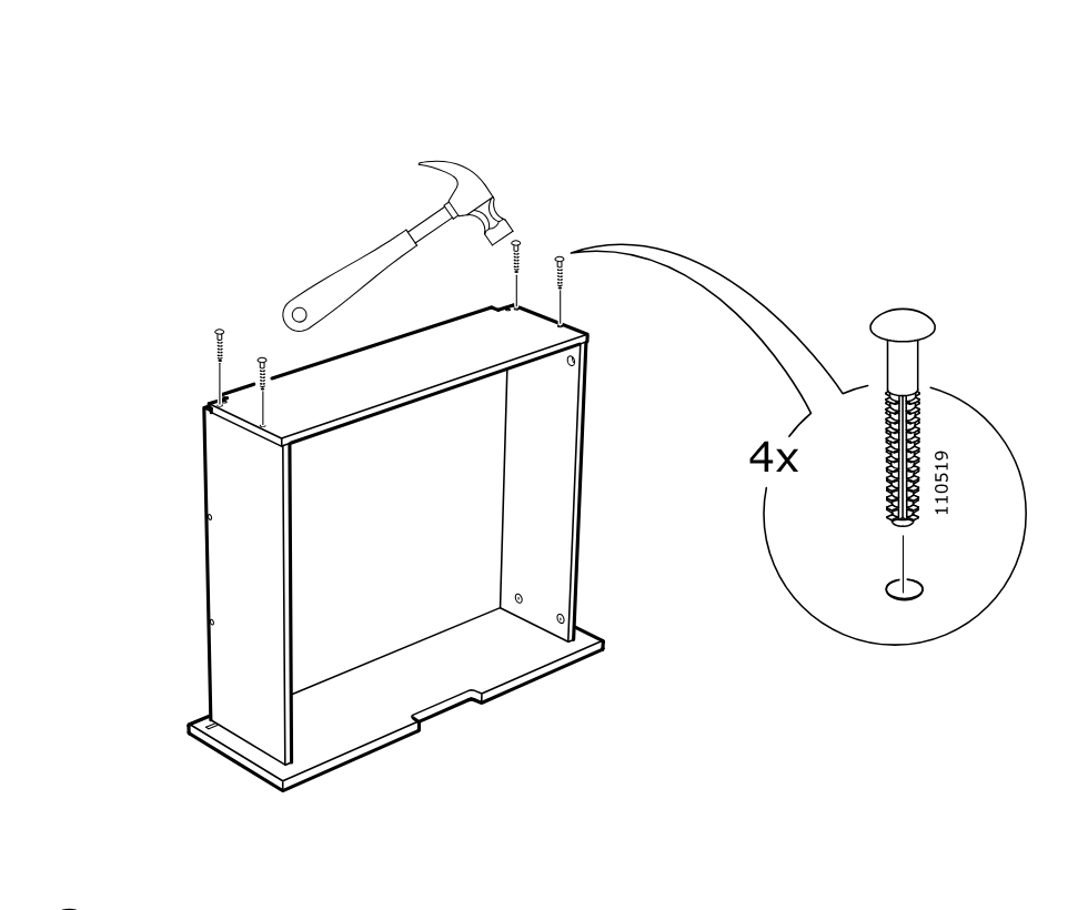
    Diagram for step 7: Hammer four 110519 nails into the predrilled holes along the top edge of the frame.
  9. Step 8

    Press four 139251 inserts into the side panel holes near the top of the frame.
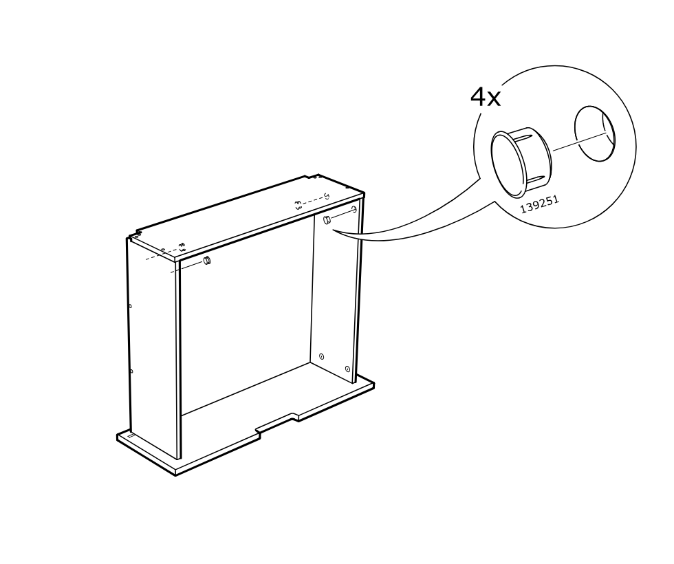
    Diagram for step 8: Press four 139251 inserts into the side panel holes near the top of the frame.
NORDLI Headboard

  1. Before you begin

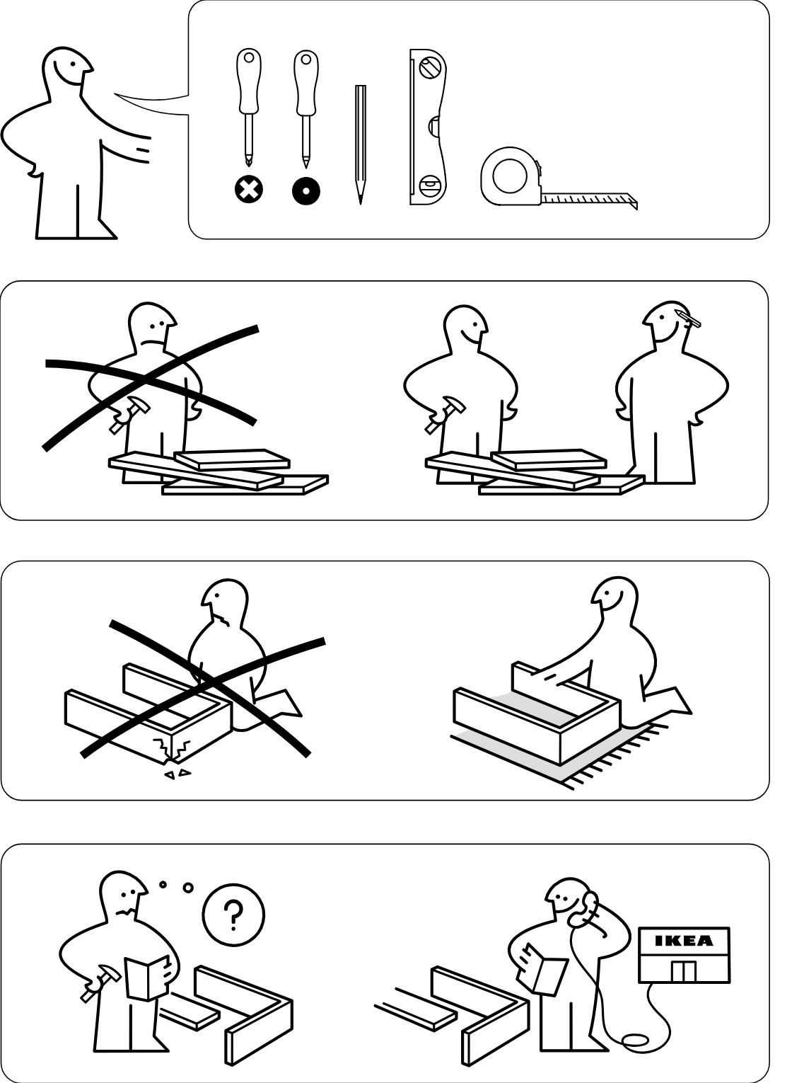
    Preparation and safety guidance panels show required tools, avoiding solo assembly, protecting parts from hard surfaces, and contacting IKEA support if instructions are unclear.

    Illustration for assembly note: Preparation and safety guidance panels show required tools, avoiding solo assembly, protecting parts from hard surfaces, and contacting IKEA support if instructions are unclear.
  2. Step 1

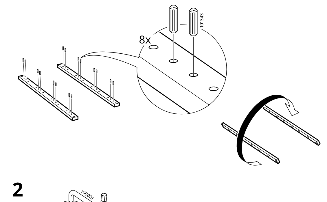
    Insert eight wooden dowels into the predrilled holes of the two long rails and orient the rails as shown.

    Diagram for step 1: Insert eight wooden dowels into the predrilled holes of the two long rails and orient the rails as shown.
  3. Step 2

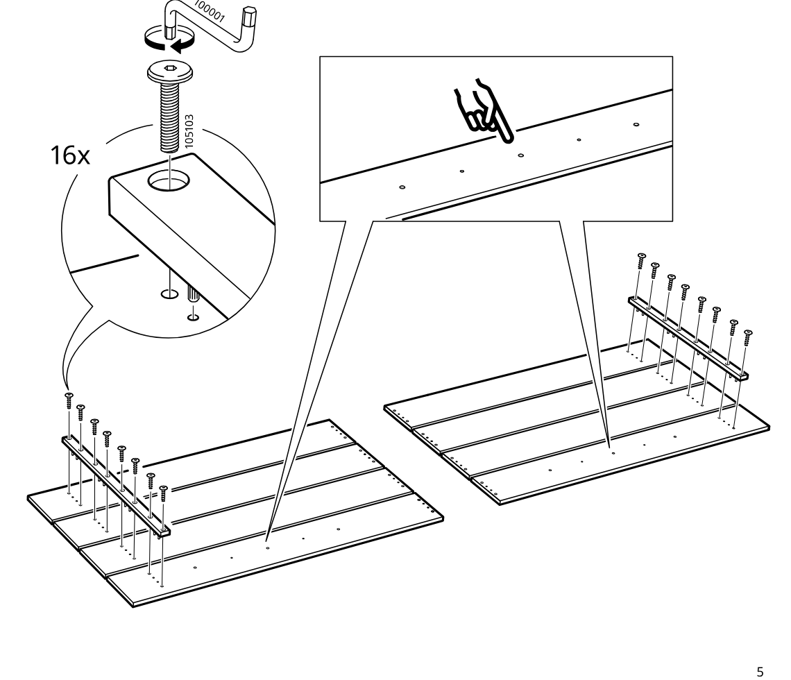
    Using the Allen key, fasten sixteen bolts through the rails into the large panel assemblies while aligning the hole pattern and rail position shown in the inset.

    Diagram for step 2: Using the Allen key, fasten sixteen bolts through the rails into the large panel assemblies while aligning the hole pattern and rail position shown in the inset.
  4. Step 3

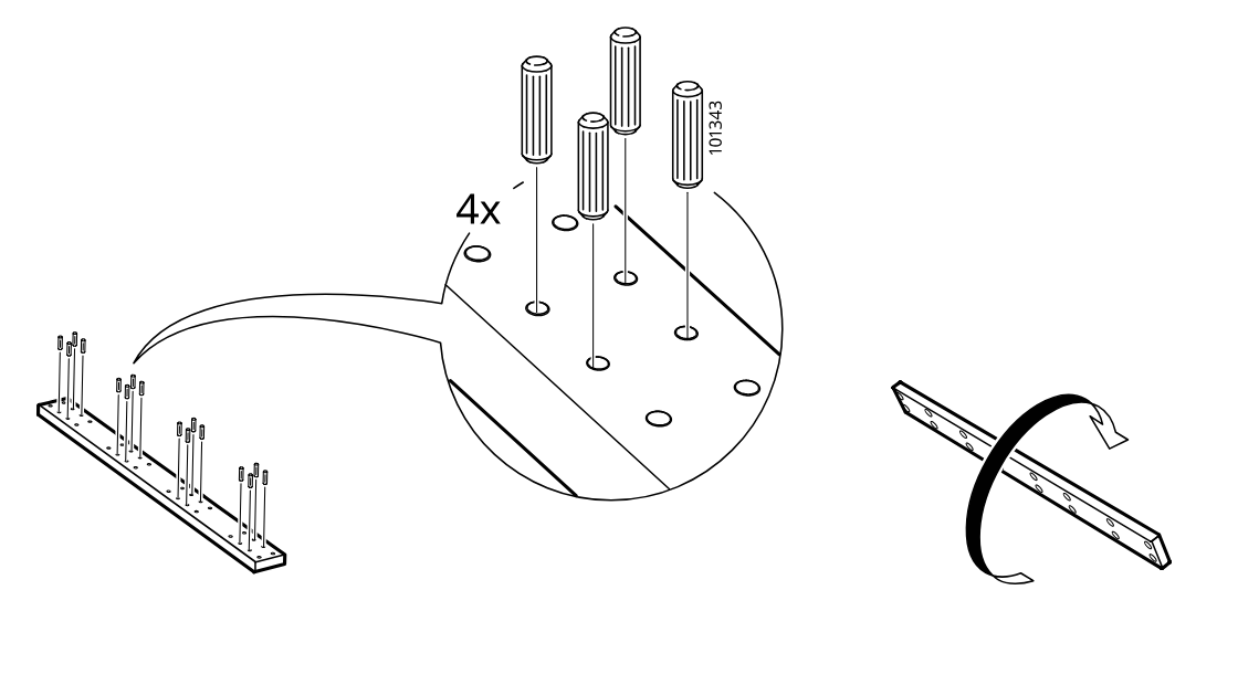
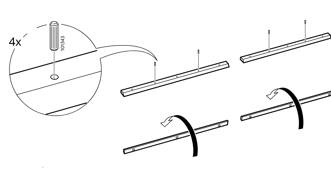
    Insert four wooden dowels (101343) into the indicated holes of the slat and turn the rail to the shown orientation.

    Diagram for step 3: Insert four wooden dowels (101343) into the indicated holes of the slat and turn the rail to the shown orientation.
  5. Step 4

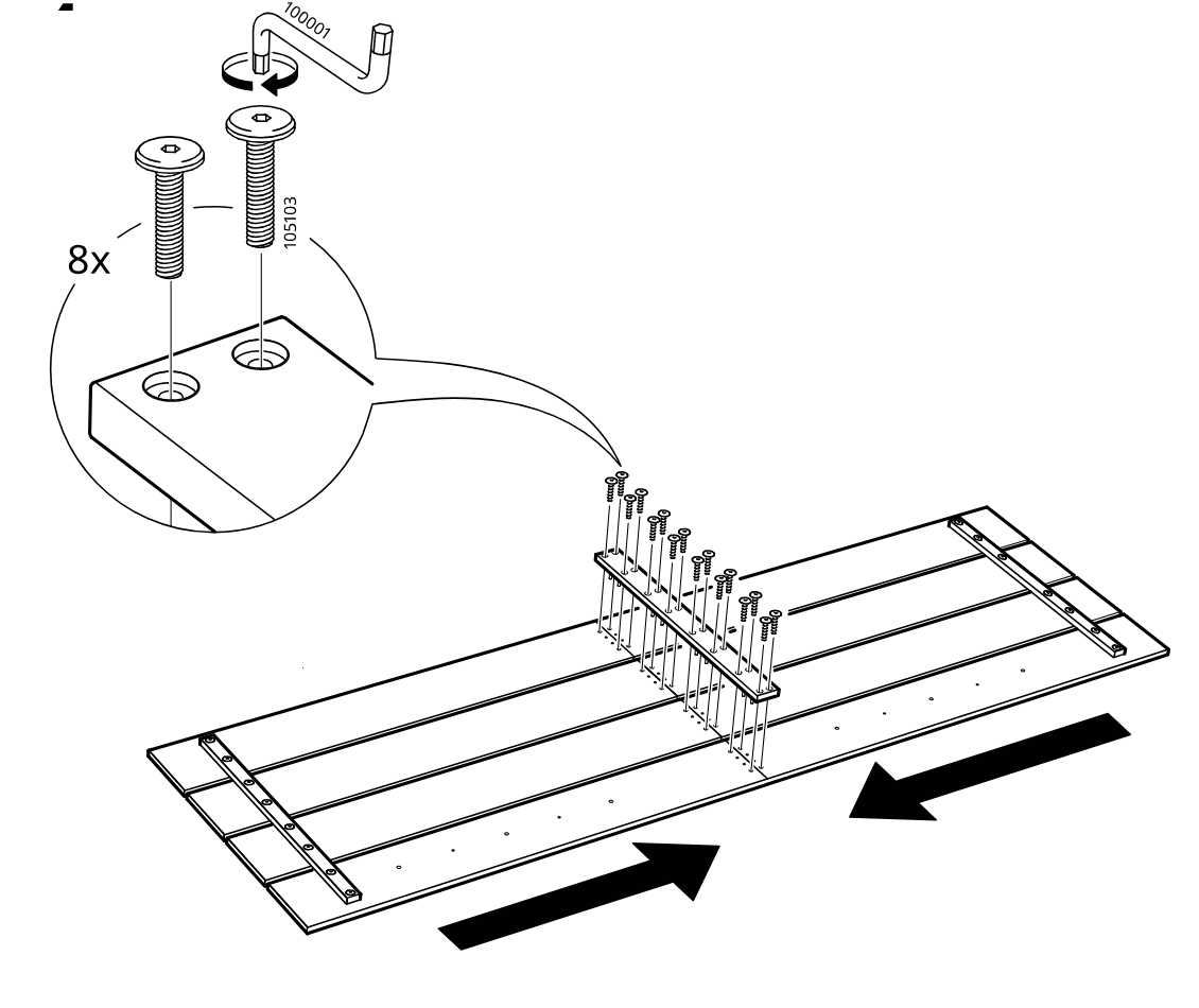
    Tighten eight bolts (105103) with the hex key (100001) into the central slat assembly while keeping the long panel sections aligned in the shown direction.

    Diagram for step 4: Tighten eight bolts (105103) with the hex key (100001) into the central slat assembly while keeping the long panel sections aligned in the shown direction.
  6. Step 5

    Insert four dowels (101343) into the rail pieces and rotate the rails to the correct orientation.

    Diagram for step 5: Insert four dowels (101343) into the rail pieces and rotate the rails to the correct orientation.
  7. Step 6

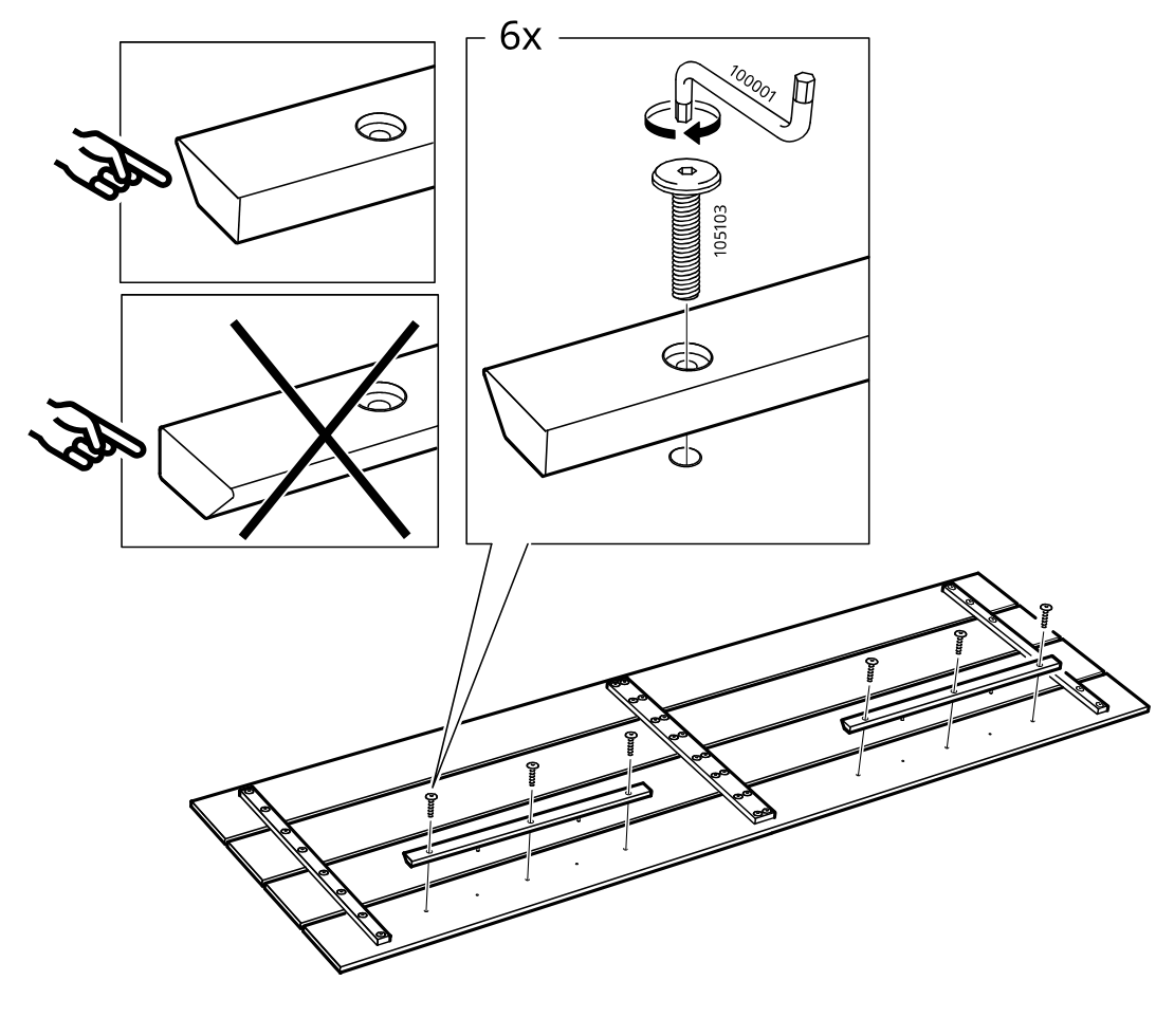
    Align each rail on the panel in the correct direction and fasten with six screws (105103) using the hex key (100001).

    Diagram for step 6: Align each rail on the panel in the correct direction and fasten with six screws (105103) using the hex key (100001).
  8. Step 7

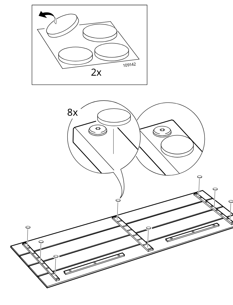
    The installer peels adhesive pads from sheet 109142 and applies 8 round pads onto the indicated rail positions on the large panel, as shown in the zoom callouts.

    Diagram for step 7: The installer peels adhesive pads from sheet 109142 and applies 8 round pads onto the indicated rail positions on the large panel, as shown in the zoom callouts.
  9. Step 8

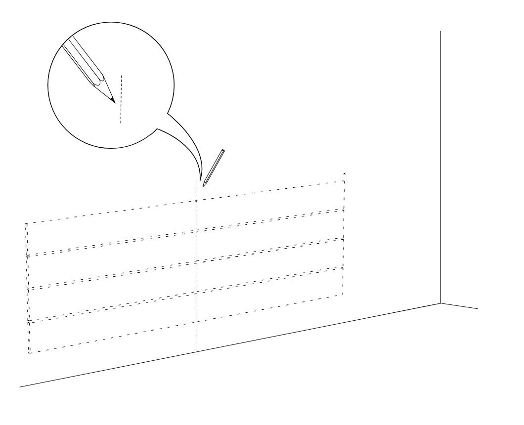
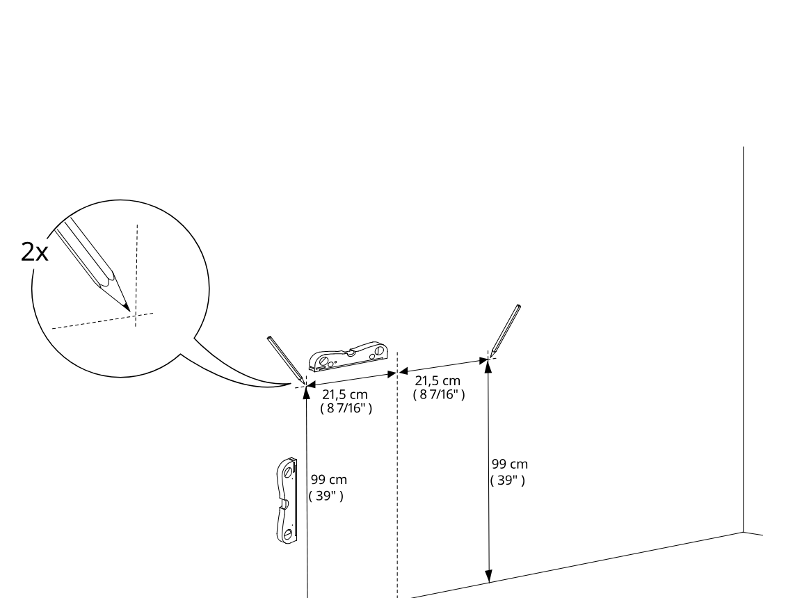
    Mark a vertical reference line with a pencil on the wall aligned to the dashed layout guide.

    Diagram for step 8: Mark a vertical reference line with a pencil on the wall aligned to the dashed layout guide.
  10. Step 9

    Mark two wall fixing points by measuring 99 cm up from the floor line and 21.5 cm to each side of the centerline, using the bracket as a guide.

    Diagram for step 9: Mark two wall fixing points by measuring 99 cm up from the floor line and 21.5 cm to each side of the centerline, using the bracket as a guide.
  11. Step 10

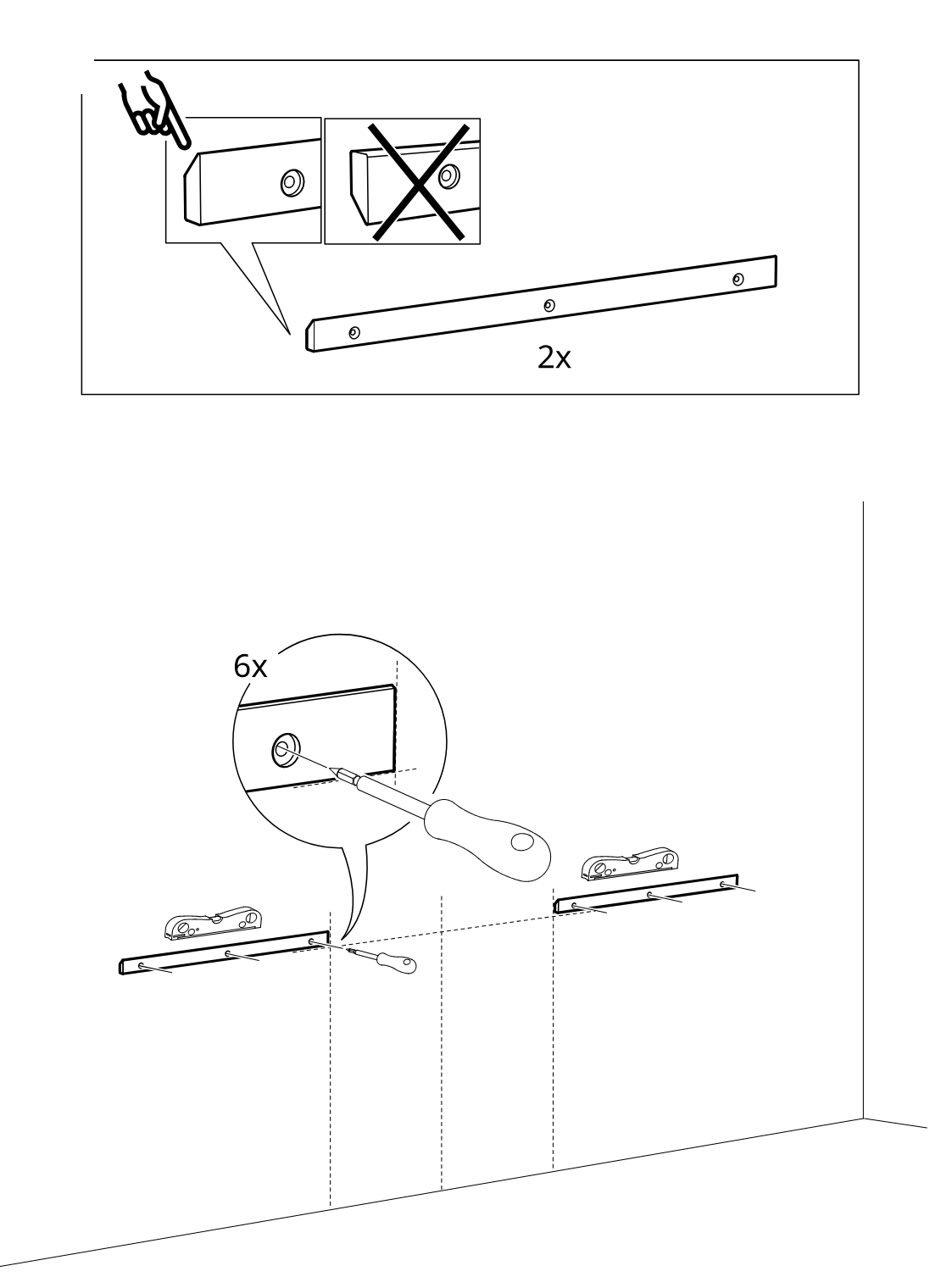
    The installer checks the rail orientation in the top instruction panel and then fastens both rails to the wall in the shown positions, tightening six screws with a screwdriver.

    Diagram for step 10: The installer checks the rail orientation in the top instruction panel and then fastens both rails to the wall in the shown positions, tightening six screws with a screwdriver.
  12. Step 11

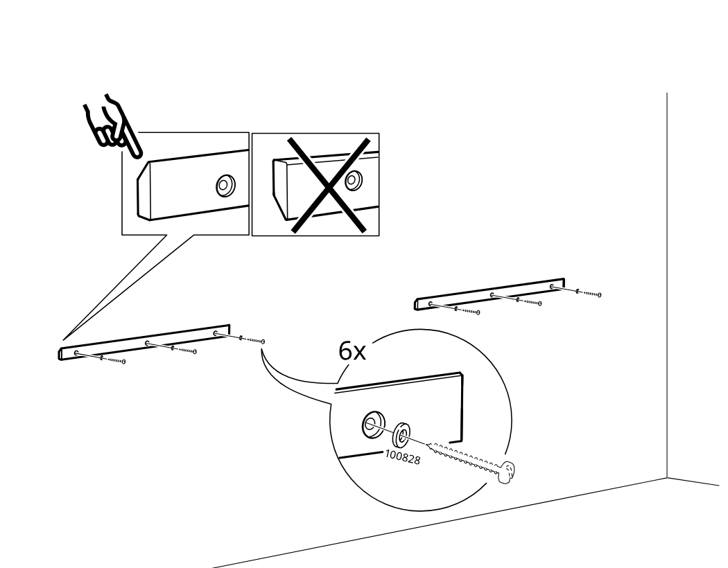
    The user installs six screws through the long rails into the panel inserts, with the callout showing correct insert orientation and the 100828 fastener detail.

    Diagram for step 11: The user installs six screws through the long rails into the panel inserts, with the callout showing correct insert orientation and the 100828 fastener detail.
  13. Step 12

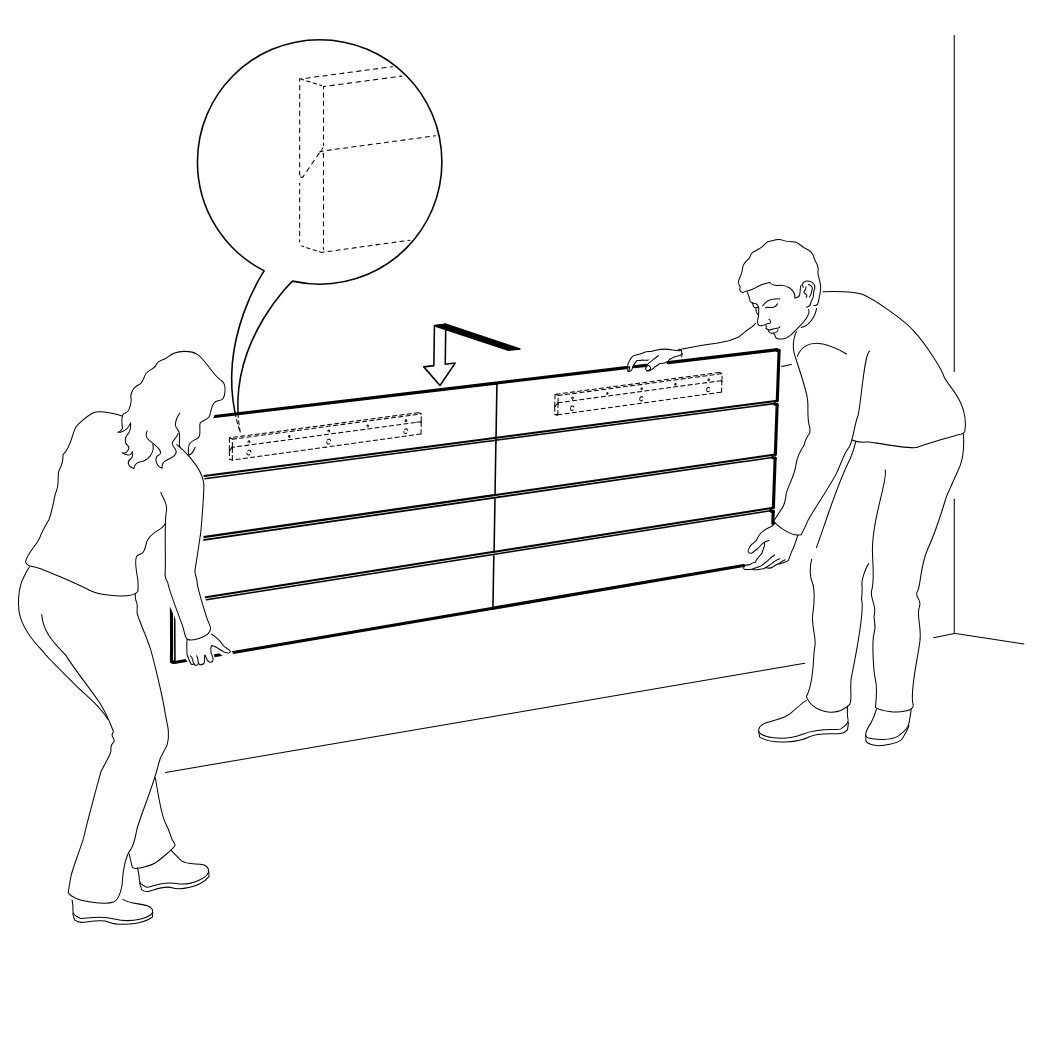
    Two people lift and position the long drawer unit against the wall while aligning the top back area as indicated by the zoom callout and downward arrow.

    Diagram for step 12: Two people lift and position the long drawer unit against the wall while aligning the top back area as indicated by the zoom callout and downward arrow.
  14. Step 13

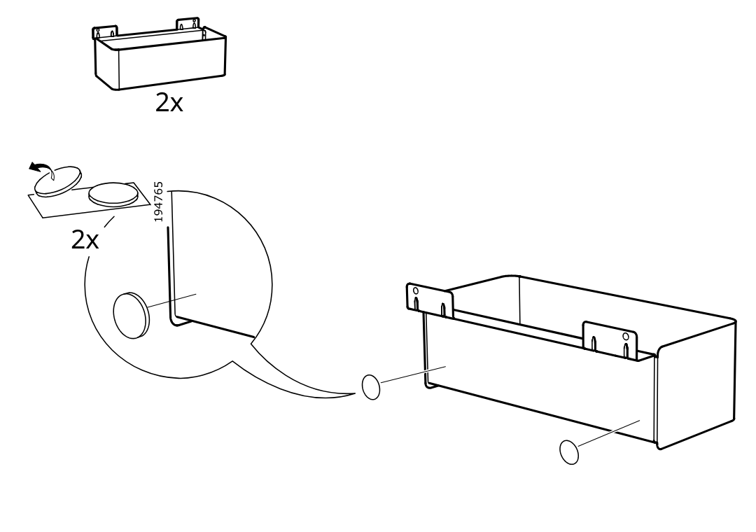
    Apply two adhesive pads (part 194765) to the indicated side positions on each of the two box components, with the zoom callout showing peel-and-stick placement.

    Diagram for step 13: Apply two adhesive pads (part 194765) to the indicated side positions on each of the two box components, with the zoom callout showing peel-and-stick placement.
  15. Step 14

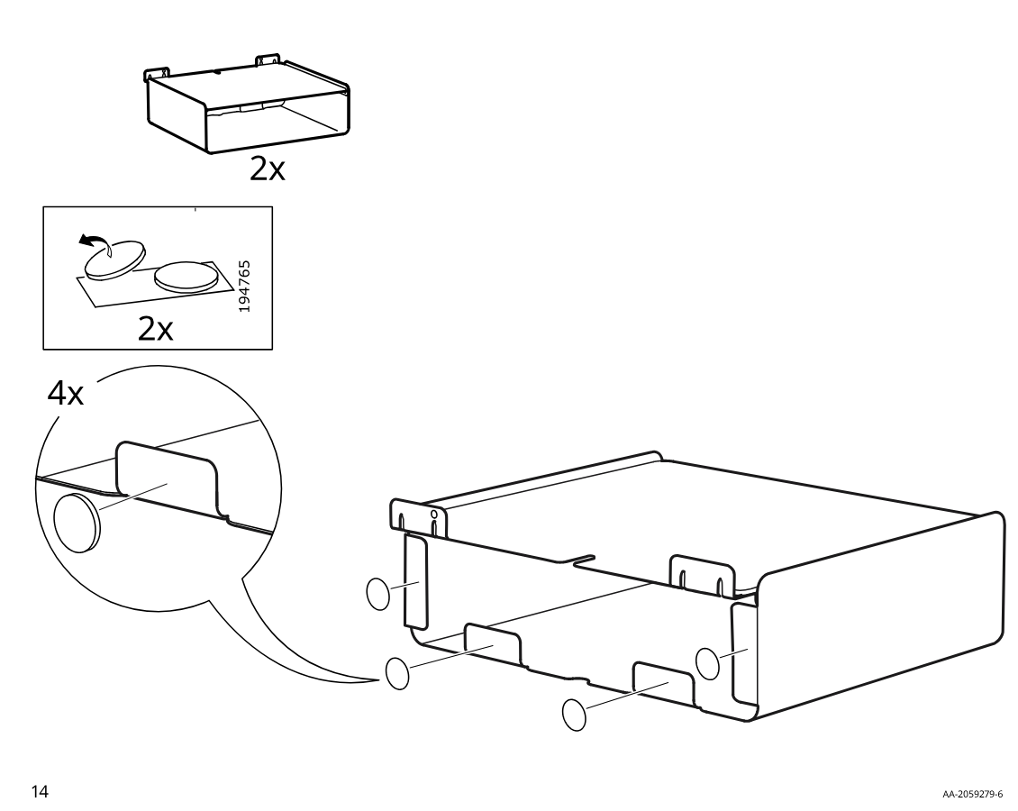
    Apply four adhesive pads (part 194765, shown as 2x twice) to the highlighted inner tab/slot contact points on each of the two assembled tray-like units as indicated by the zoom callout and arrows.

    Diagram for step 14: Apply four adhesive pads (part 194765, shown as 2x twice) to the highlighted inner tab/slot contact points on each of the two assembled tray-like units as indicated by the zoom callout and arrows.
  16. Step 15

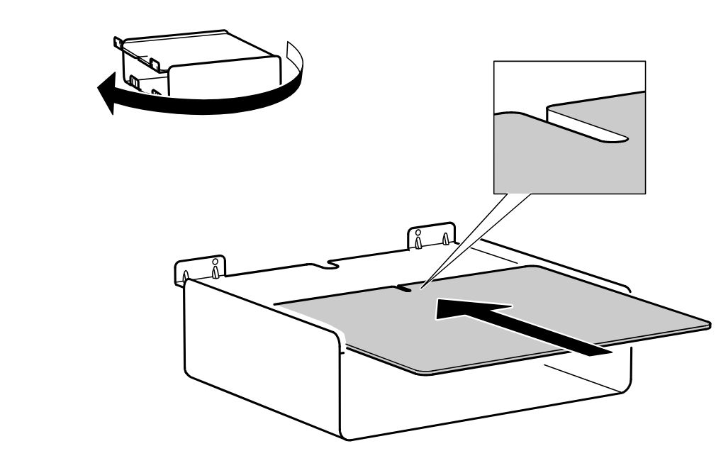
    The drawer tray is rotated and the inner panel is slid into the top slot, with a zoom callout showing the edge alignment detail.

    Diagram for step 15: The drawer tray is rotated and the inner panel is slid into the top slot, with a zoom callout showing the edge alignment detail.
  17. Step 16

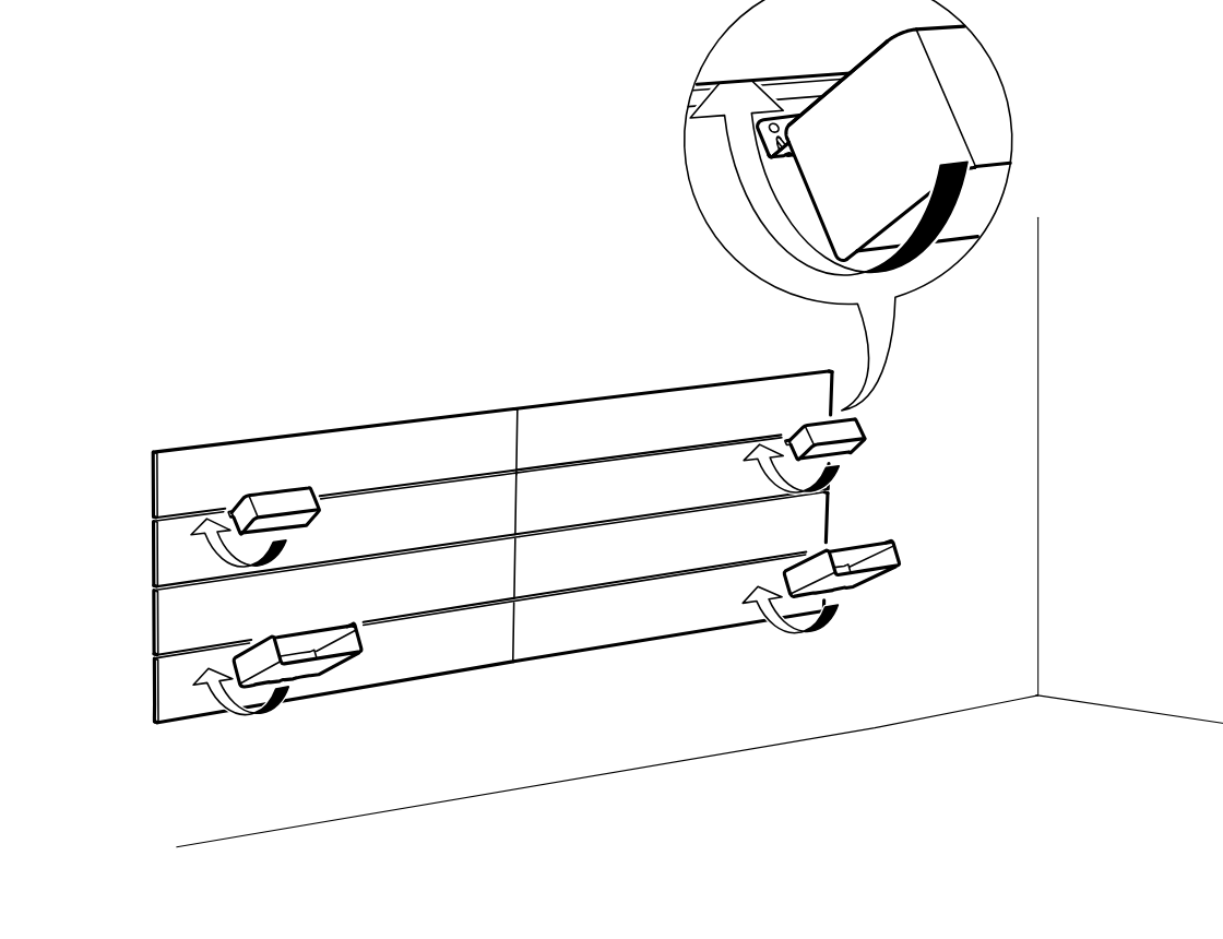
    The assembled drawer fronts are adjusted by rotating the four locking clips upward, with a zoom callout showing clip movement and engagement.

    Diagram for step 16: The assembled drawer fronts are adjusted by rotating the four locking clips upward, with a zoom callout showing clip movement and engagement.
  18. Before you begin

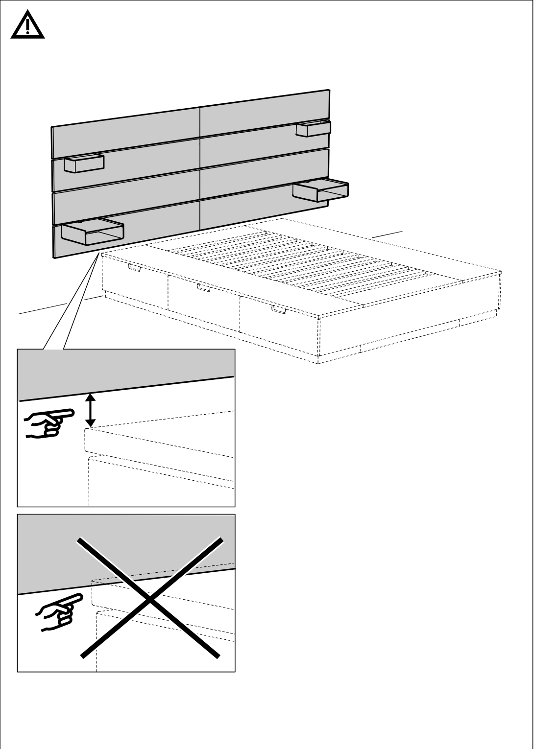
    Safety guidance panel shows how to position the wall rail relative to the bed frame, with one correct alignment example and one incorrect crossed-out example.

    Illustration for assembly note: Safety guidance panel shows how to position the wall rail relative to the bed frame, with one correct alignment example and one incorrect crossed-out example.

Video guide