How to assemble IKEA SONGESAND bed frame

SONGESAND bed frame, brown/Luröy, Queen

This guide covers the IKEA SONGESAND Queen bed frame in brown/LURÖY, combination 592.410.69. Open the SONGESAND bed-frame instructions to follow the diagrams and video.

View on IKEA
SONGESAND bed frame

Interactive assembly guide

Step-by-Step Instructions

1 different parts, 1 boxes total — click on a package to see step-by-step assembly instructions

SONGESAND Bed frame

403.725.31

x1

20 "

Width

2 "

Height

73 "

Length

47 lb 10 oz

Weight

Start Assembly

Written guide

Step-by-step instructions with diagrams

Follow the numbered assembly steps below, or open the interactive guide above to track progress and zoom into each diagram. This guide includes 38 illustrated steps.

SONGESAND Bed frame

  1. Before you begin

    Preparation and safety guidance shows required tools (Phillips and flat screwdriver plus hammer), advises against assembling alone, warns not to assemble on a hard floor, and instructs to read instructions or contact IKEA support if unsure.
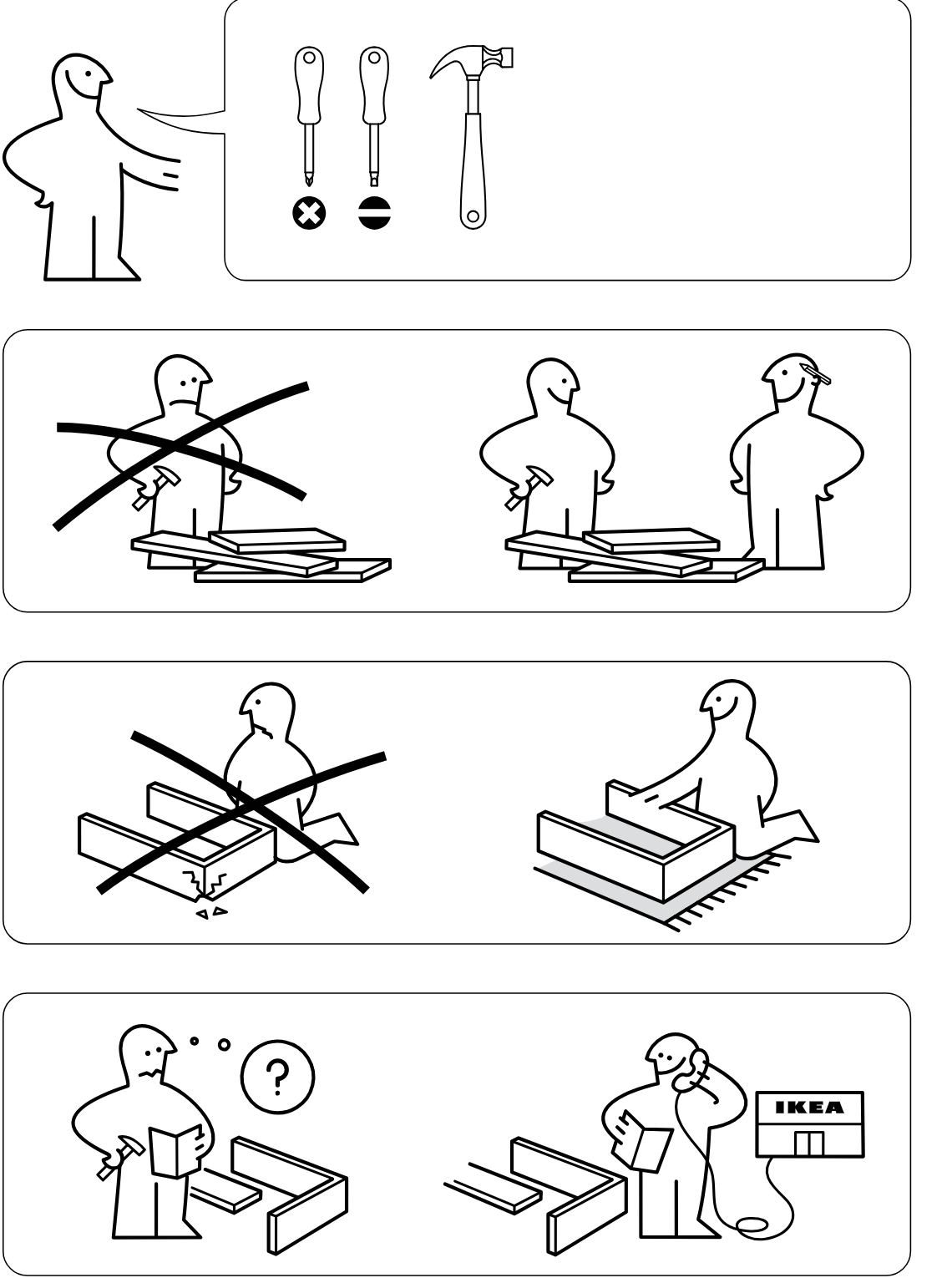
    Illustration for assembly note: Preparation and safety guidance shows required tools (Phillips and flat screwdriver plus hammer), advises against assembling alone, warns not to assemble on a hard floor, and instructs to read instructions or contact IKEA support if unsure.
  2. Before you begin

    Parts-bag panel 1 shows required hardware: dowel 101356 (16x), connector pin 153507 (4x), and cam lock 119253/118137 (4x).
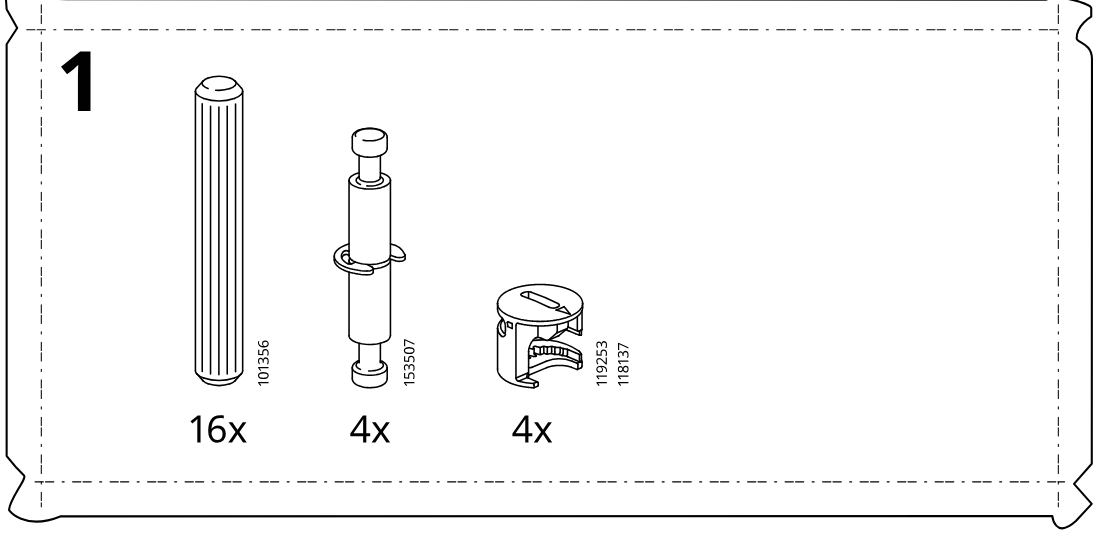
    Illustration for assembly note: Parts-bag panel 1 shows required hardware: dowel 101356 (16x), connector pin 153507 (4x), and cam lock 119253/118137 (4x).
  3. Before you begin

    Parts-bag panel 2 shows required hardware: dowel 101356 (6x), connector pin 153507 (6x), cam lock 110630 (16x), and rail/bracket 153548/158568 (2x).
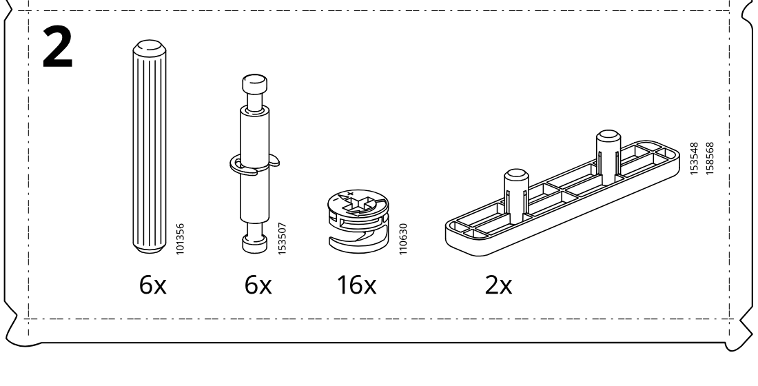
    Illustration for assembly note: Parts-bag panel 2 shows required hardware: dowel 101356 (6x), connector pin 153507 (6x), cam lock 110630 (16x), and rail/bracket 153548/158568 (2x).
  4. Before you begin

    Parts-bag reference panel labeled 3 showing required hardware and tools with quantities and vertical part numbers.
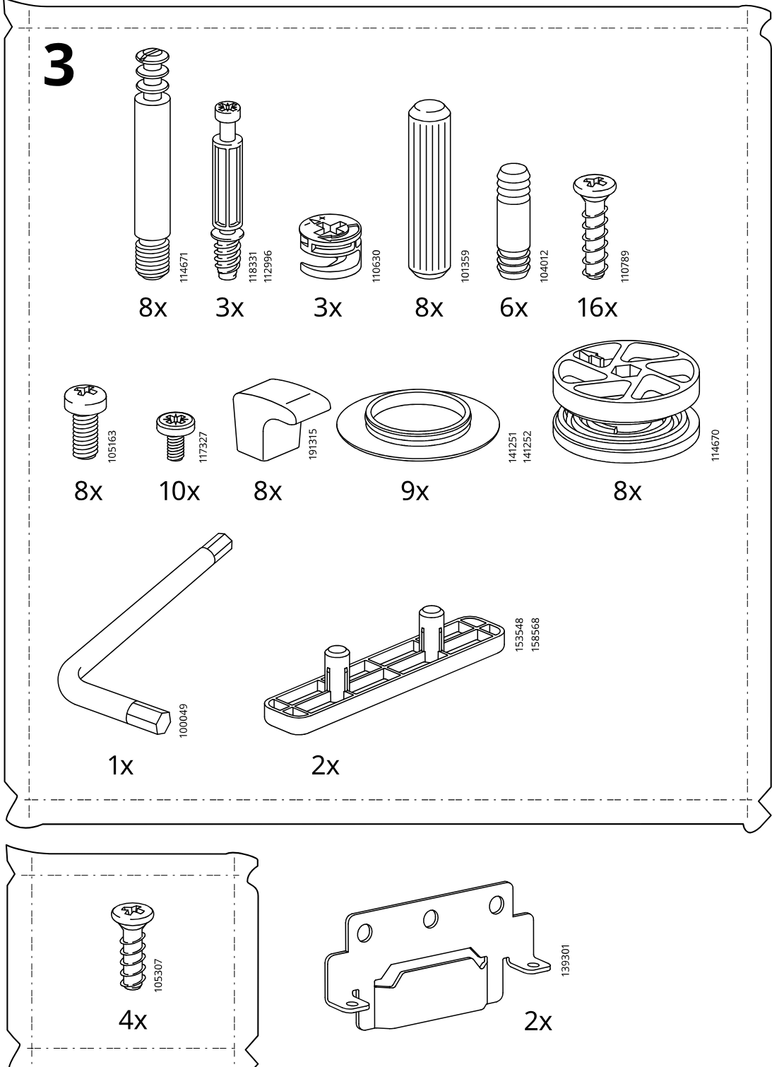
    Illustration for assembly note: Parts-bag reference panel labeled 3 showing required hardware and tools with quantities and vertical part numbers.
  5. Before you begin

    Small parts-bag reference panel showing screw part 105307 with quantity 4x.
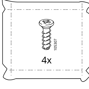
    Illustration for assembly note: Small parts-bag reference panel showing screw part 105307 with quantity 4x.
  6. Step 1

    Insert sixteen ribbed wooden dowels into the edge holes of the two panels, as indicated by the enlarged 16x zoom detail.
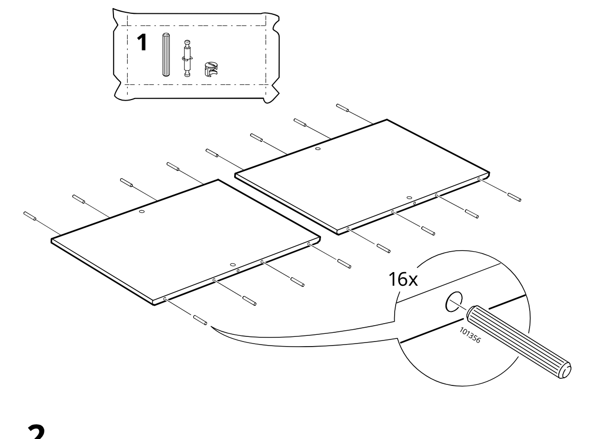
    Diagram for step 1: Insert sixteen ribbed wooden dowels into the edge holes of the two panels, as indicated by the enlarged 16x zoom detail.
  7. Step 2

    Install four cam screws into the panel edge holes, place cam locks into the large face holes, and rotate the cam locks with a screwdriver to secure.
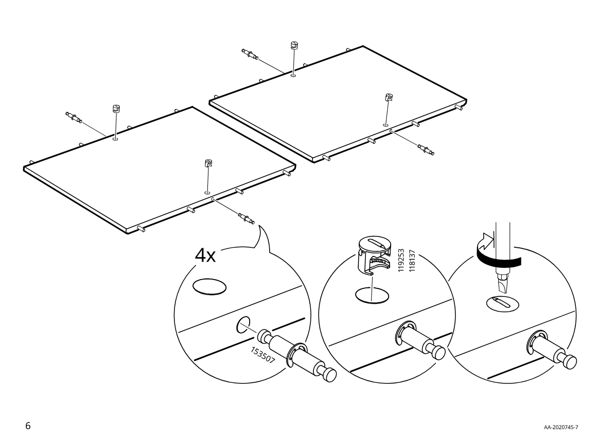
    Diagram for step 2: Install four cam screws into the panel edge holes, place cam locks into the large face holes, and rotate the cam locks with a screwdriver to secure.
  8. Step 3

    The long rail is fitted with two connector bolts and cam locks, then the cam locks are tightened as shown in the zoom circles.
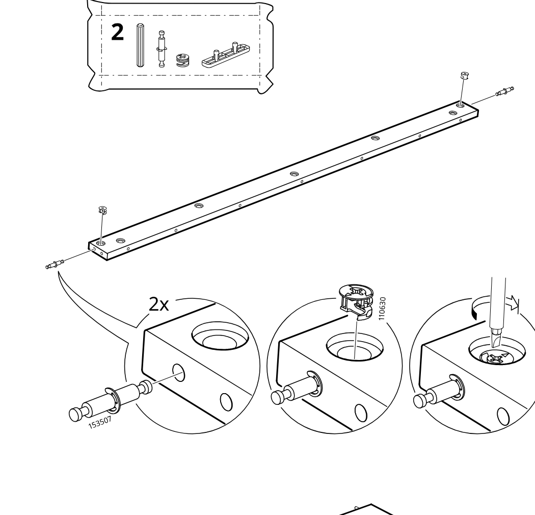
    Diagram for step 3: The long rail is fitted with two connector bolts and cam locks, then the cam locks are tightened as shown in the zoom circles.
  9. Step 4

    Two large panels are aligned and lowered onto the prepared long rail, with arrows indicating the assembly direction.
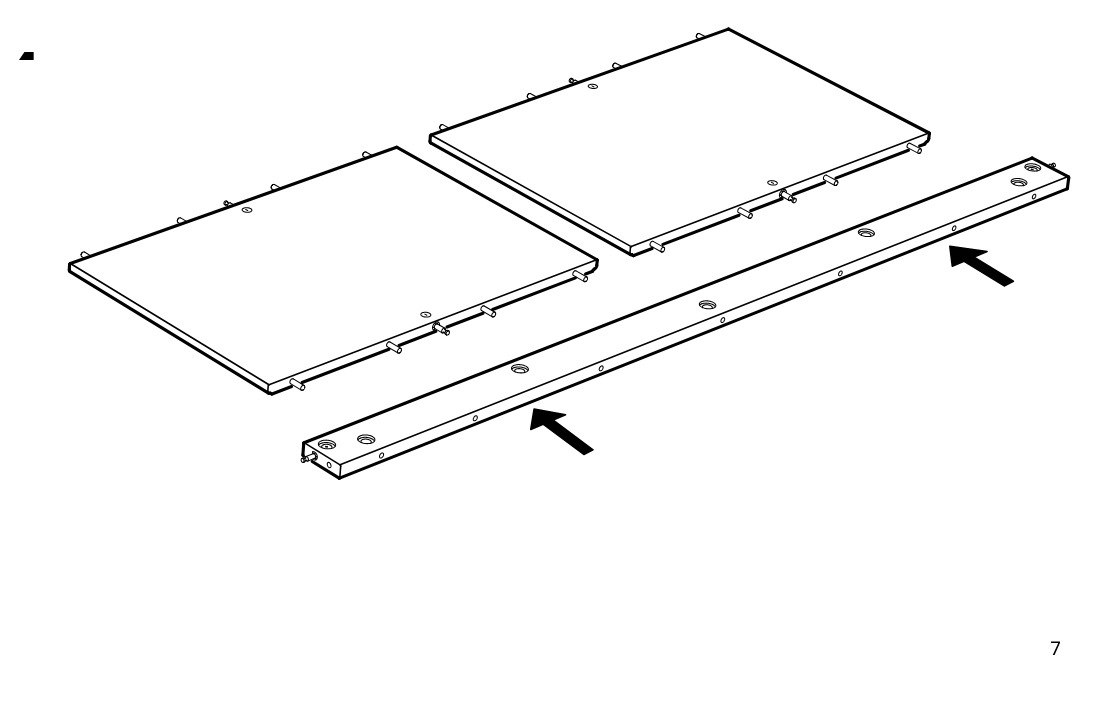
    Diagram for step 4: Two large panels are aligned and lowered onto the prepared long rail, with arrows indicating the assembly direction.
  10. Step 5

    Two cam locks are inserted and tightened in the top rail, then the panel assembly is rotated downward into position.
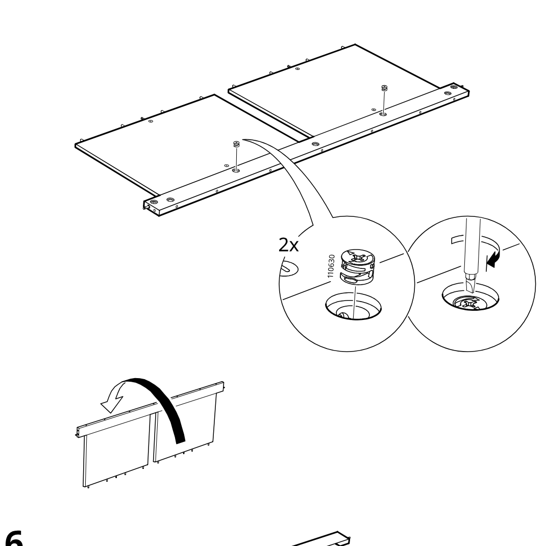
    Diagram for step 5: Two cam locks are inserted and tightened in the top rail, then the panel assembly is rotated downward into position.
  11. Step 6

    The long board is oriented using the arrows and aligned beneath the two panel pieces and top rail for the next connection.
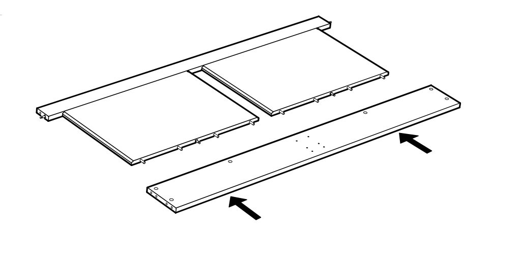
    Diagram for step 6: The long board is oriented using the arrows and aligned beneath the two panel pieces and top rail for the next connection.
  12. Step 7

    The panel assembly is positioned and two cam locks (110630) are inserted into the large holes and turned with a screwdriver to lock.
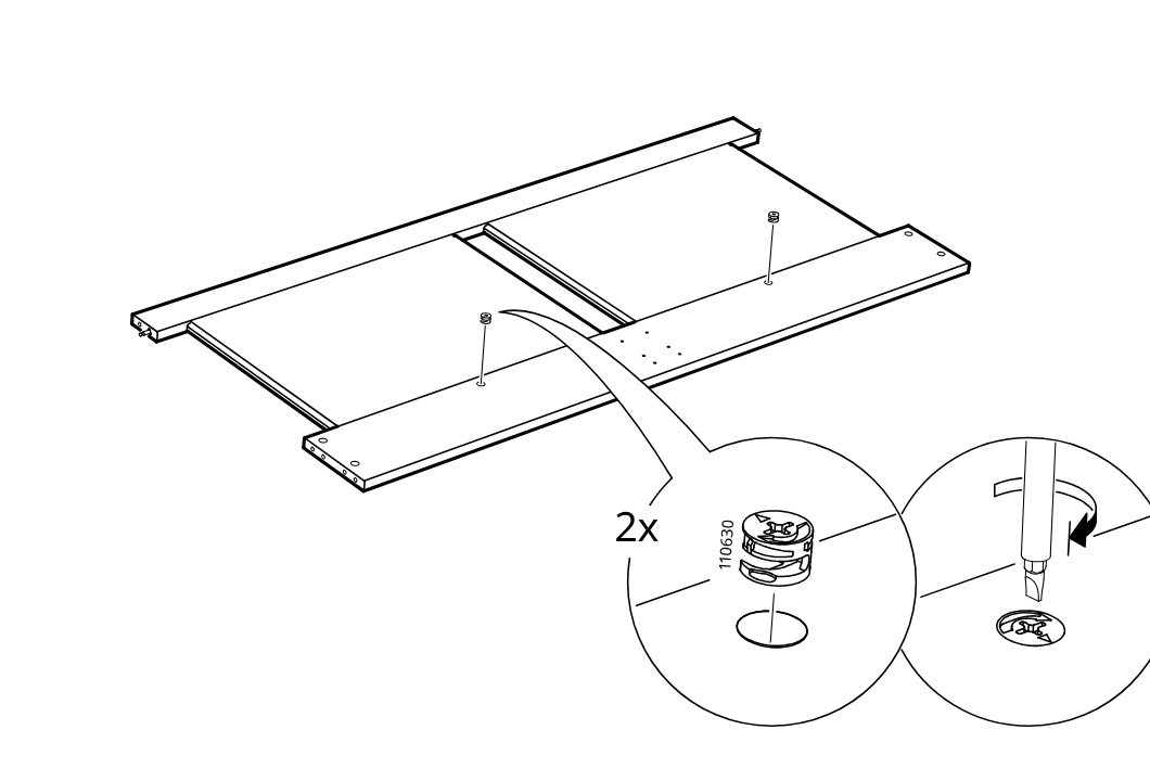
    Diagram for step 7: The panel assembly is positioned and two cam locks (110630) are inserted into the large holes and turned with a screwdriver to lock.
  13. Step 8

    Four connector pins (153507) are pushed into edge holes, then cam locks (110630) are inserted and turned with a screwdriver to secure them.
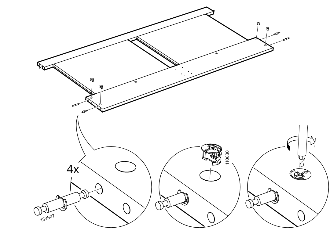
    Diagram for step 8: Four connector pins (153507) are pushed into edge holes, then cam locks (110630) are inserted and turned with a screwdriver to secure them.
  14. Step 9

    Insert six cam fasteners and dowel pins into the panel assembly, as shown in the zoomed detail marked 6x.
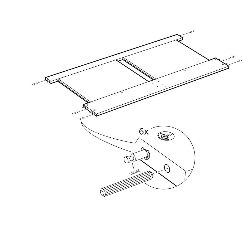
    Diagram for step 9: Insert six cam fasteners and dowel pins into the panel assembly, as shown in the zoomed detail marked 6x.
  15. Step 10

    Position the two long side rails with the indicated hole orientation and slide them onto the main panel assembly from both sides.
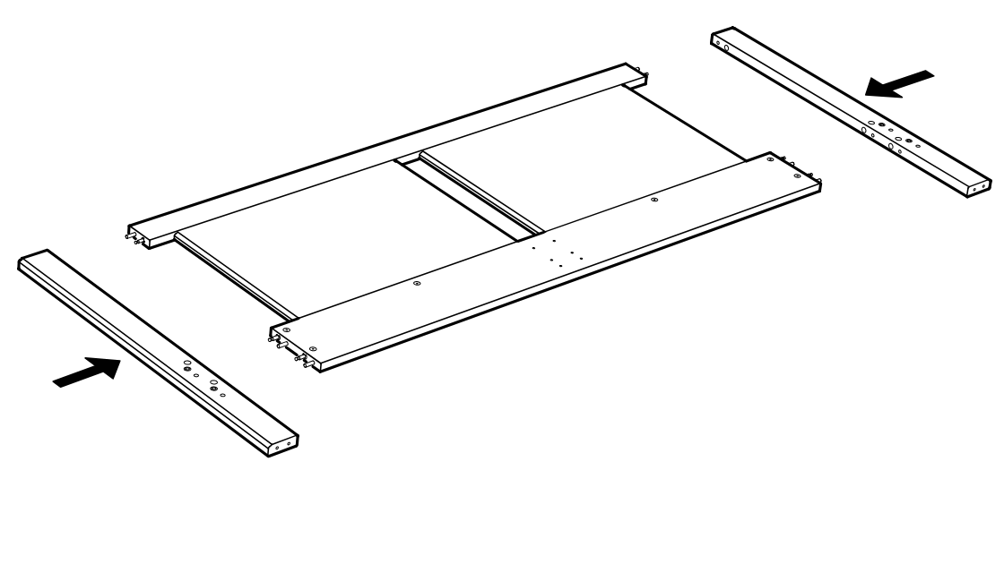
    Diagram for step 10: Position the two long side rails with the indicated hole orientation and slide them onto the main panel assembly from both sides.
  16. Step 11

    Insert and lock four cam fittings into the side holes of the frame using a screwdriver rotation.
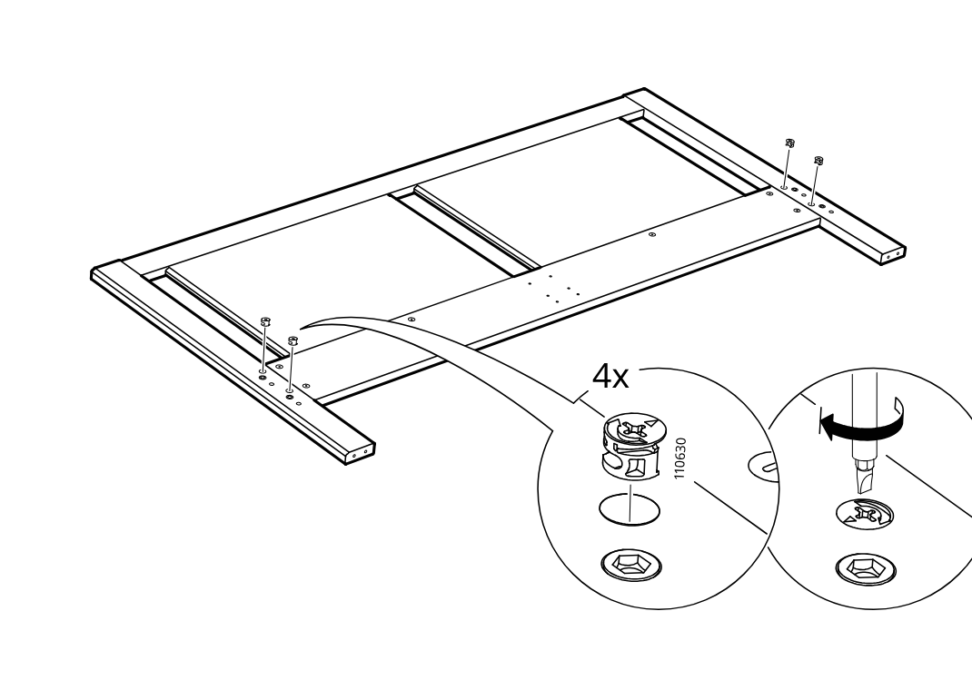
    Diagram for step 11: Insert and lock four cam fittings into the side holes of the frame using a screwdriver rotation.
  17. Step 12

    Insert two dowel-like pins into the frame ends and press in two plastic end caps by hand.
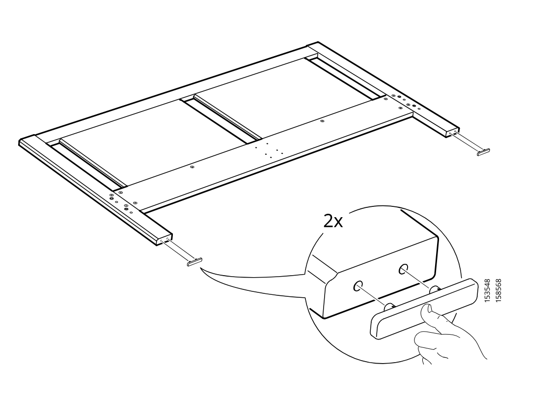
    Diagram for step 12: Insert two dowel-like pins into the frame ends and press in two plastic end caps by hand.
  18. Step 13

    The frame panel is rotated down into position and two cam locks (110630) are inserted and turned to secure the panel.
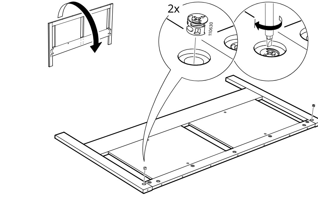
    Diagram for step 13: The frame panel is rotated down into position and two cam locks (110630) are inserted and turned to secure the panel.
  19. Step 15

    Two long boards are prepared by inserting eight cam locks into the predrilled end holes, as shown in the zoomed detail.
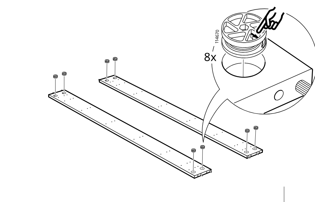
    Diagram for step 15: Two long boards are prepared by inserting eight cam locks into the predrilled end holes, as shown in the zoomed detail.
  20. Step 16

    The long board is fixed between the side frame posts with four connector bolts and tightened from the cam side, as shown in the zoomed detail.
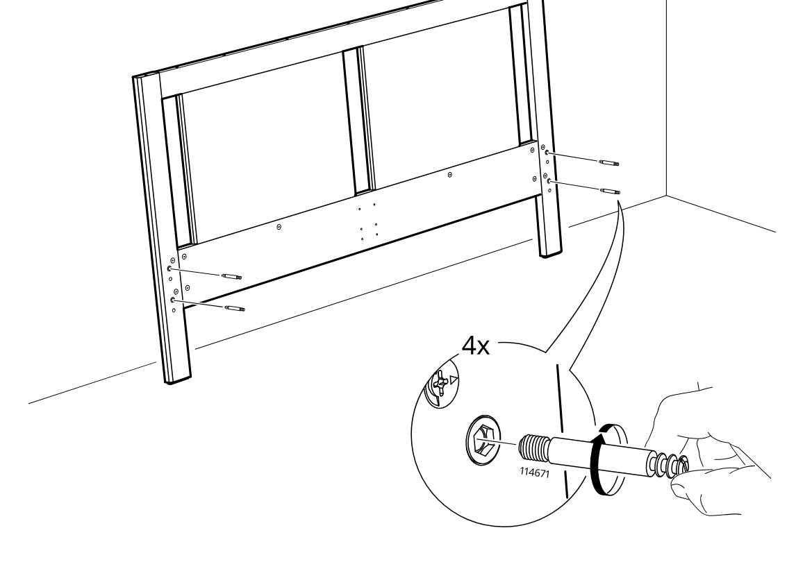
    Diagram for step 16: The long board is fixed between the side frame posts with four connector bolts and tightened from the cam side, as shown in the zoomed detail.
  21. Step 17

    The long side rail is aligned to the frame side and the cam locks at both ends are tightened with the Allen key, as shown in the four inset close-ups.
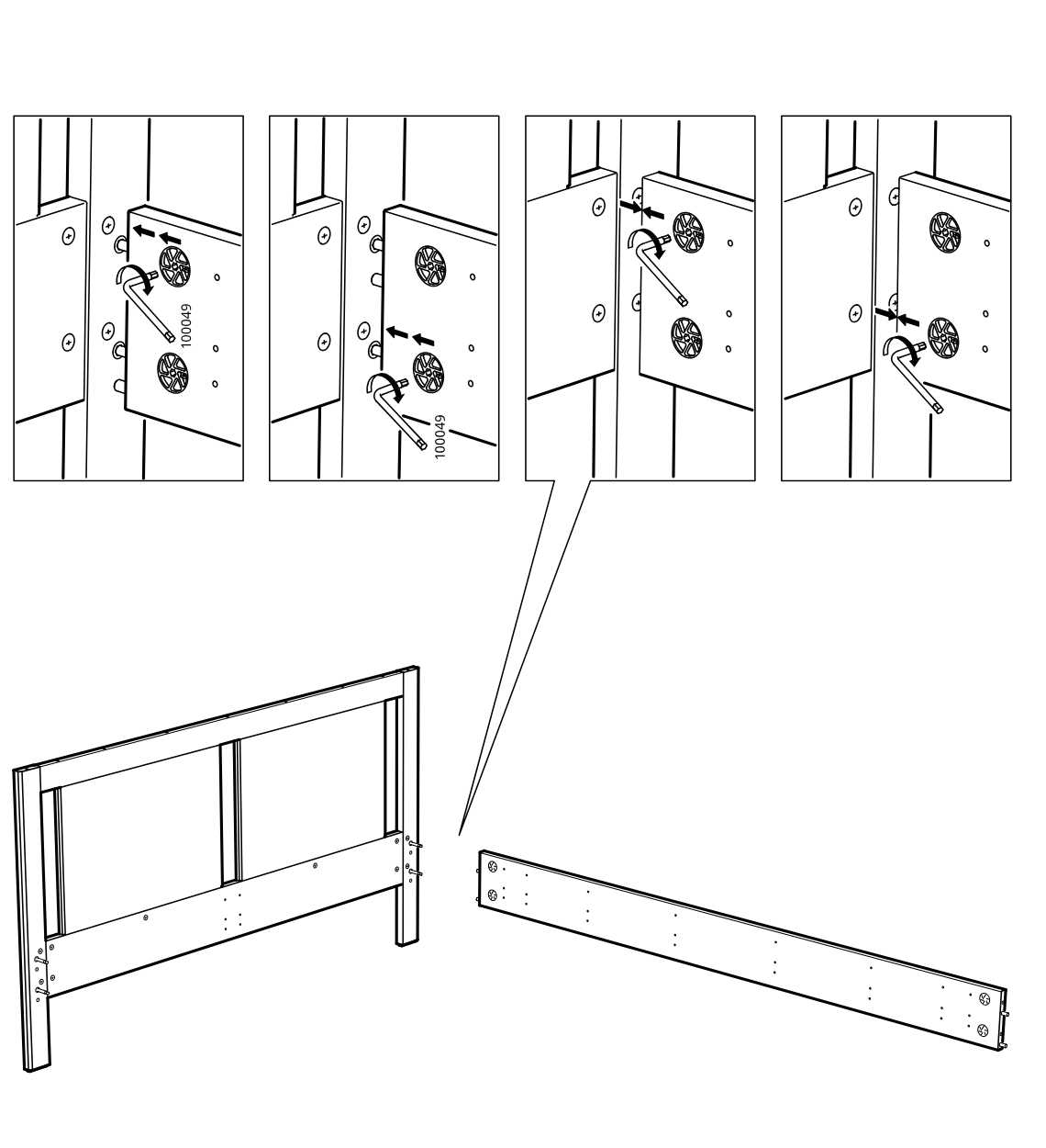
    Diagram for step 17: The long side rail is aligned to the frame side and the cam locks at both ends are tightened with the Allen key, as shown in the four inset close-ups.
  22. Step 18

    The side rails are aligned to the headboard posts and connected, while the cam locks are tightened using the shown turning sequence in the zoom callouts.
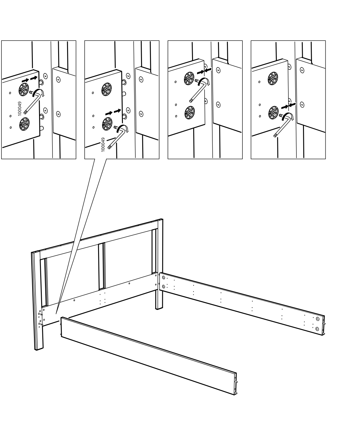
    Diagram for step 18: The side rails are aligned to the headboard posts and connected, while the cam locks are tightened using the shown turning sequence in the zoom callouts.
  23. Step 19

    Two plastic connector pieces are inserted into the end holes of the panel, with a zoom callout showing their orientation and placement.
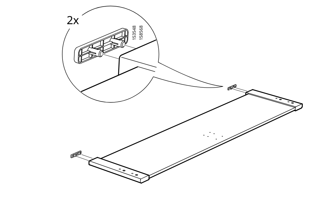
    Diagram for step 19: Two plastic connector pieces are inserted into the end holes of the panel, with a zoom callout showing their orientation and placement.
  24. Step 20

    Four threaded posts are screwed by hand into the predrilled holes at both ends of the panel, with zoom and rotation direction shown.
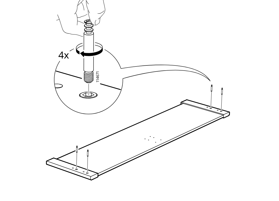
    Diagram for step 20: Four threaded posts are screwed by hand into the predrilled holes at both ends of the panel, with zoom and rotation direction shown.
  25. Step 21

    Two people align and press the side and front bed frame panels into position around the headboard frame, pushing the joints together as indicated by arrows.
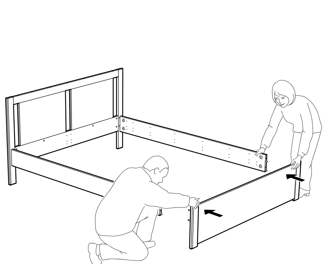
    Diagram for step 21: Two people align and press the side and front bed frame panels into position around the headboard frame, pushing the joints together as indicated by arrows.
  26. Step 22

    The side and end frame pieces are joined and two cam locks are tightened on each side using the four close-up tightening sequences shown above.
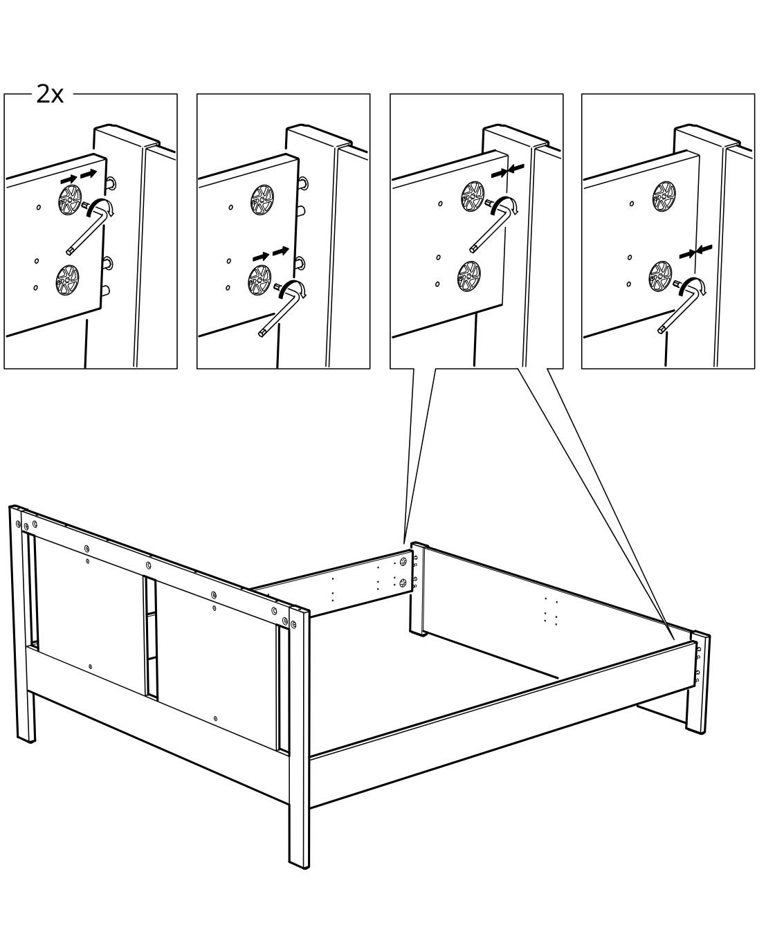
    Diagram for step 22: The side and end frame pieces are joined and two cam locks are tightened on each side using the four close-up tightening sequences shown above.
  27. Step 23

    The side frame is assembled with six 104012 threaded studs, with a hammer indicated for insertion and a crossed-out warning not to use the separate ring piece in the shown hole.
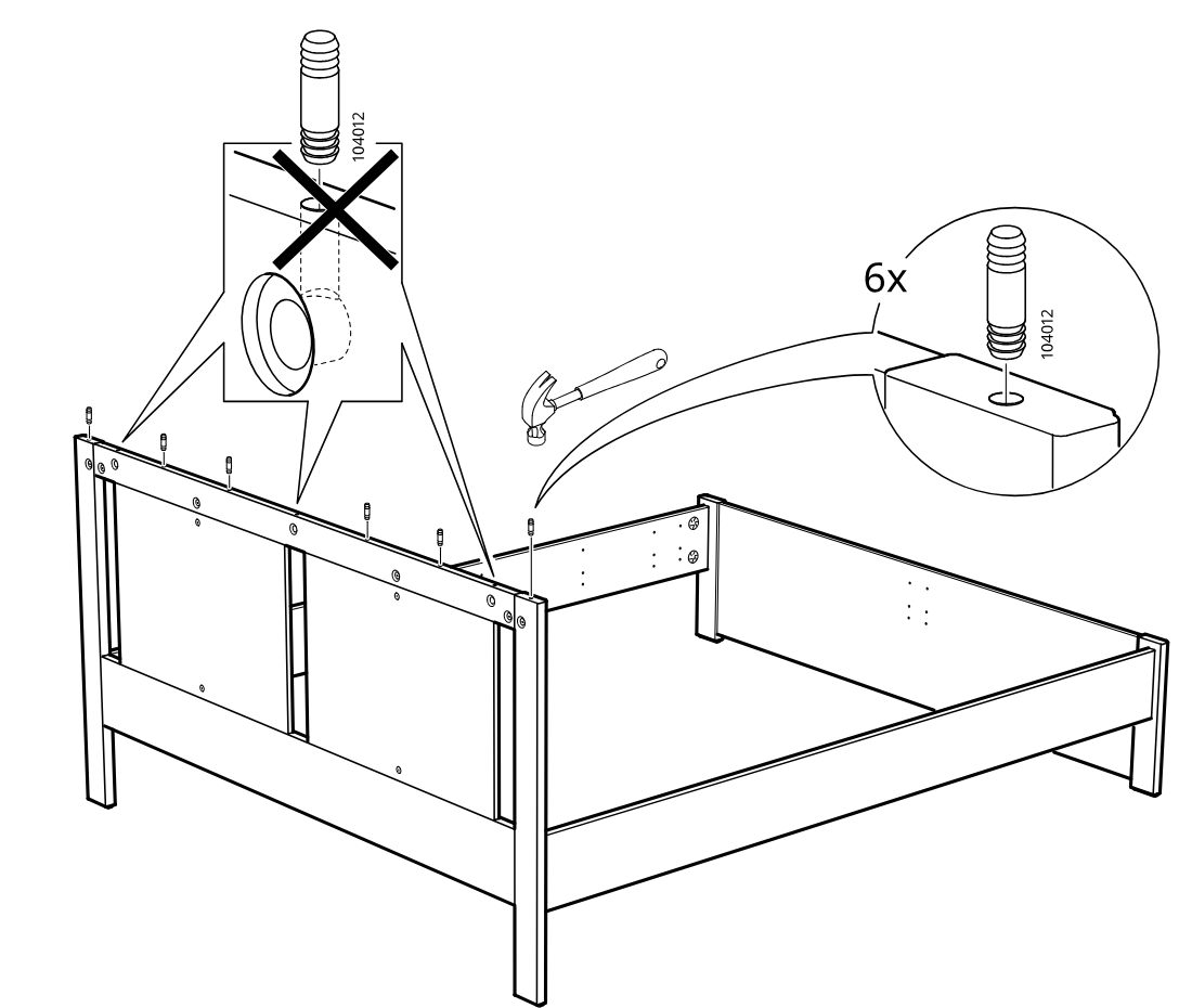
    Diagram for step 23: The side frame is assembled with six 104012 threaded studs, with a hammer indicated for insertion and a crossed-out warning not to use the separate ring piece in the shown hole.
  28. Step 24

    Three 118331/112996 fasteners are installed into the long rail at the marked positions.
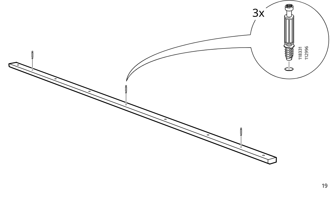
    Diagram for step 24: Three 118331/112996 fasteners are installed into the long rail at the marked positions.
  29. Step 25

    The long top rail is aligned and lowered onto the headboard edge while the finger callout indicates pressing it fully into position.
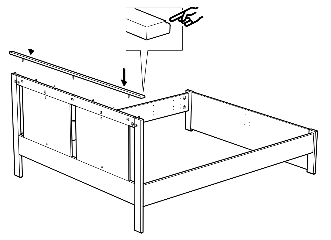
    Diagram for step 25: The long top rail is aligned and lowered onto the headboard edge while the finger callout indicates pressing it fully into position.
  30. Step 26

    Three cam locks (110630) are inserted into the headboard side and then tightened with a screwdriver, as shown in the zoom callouts.
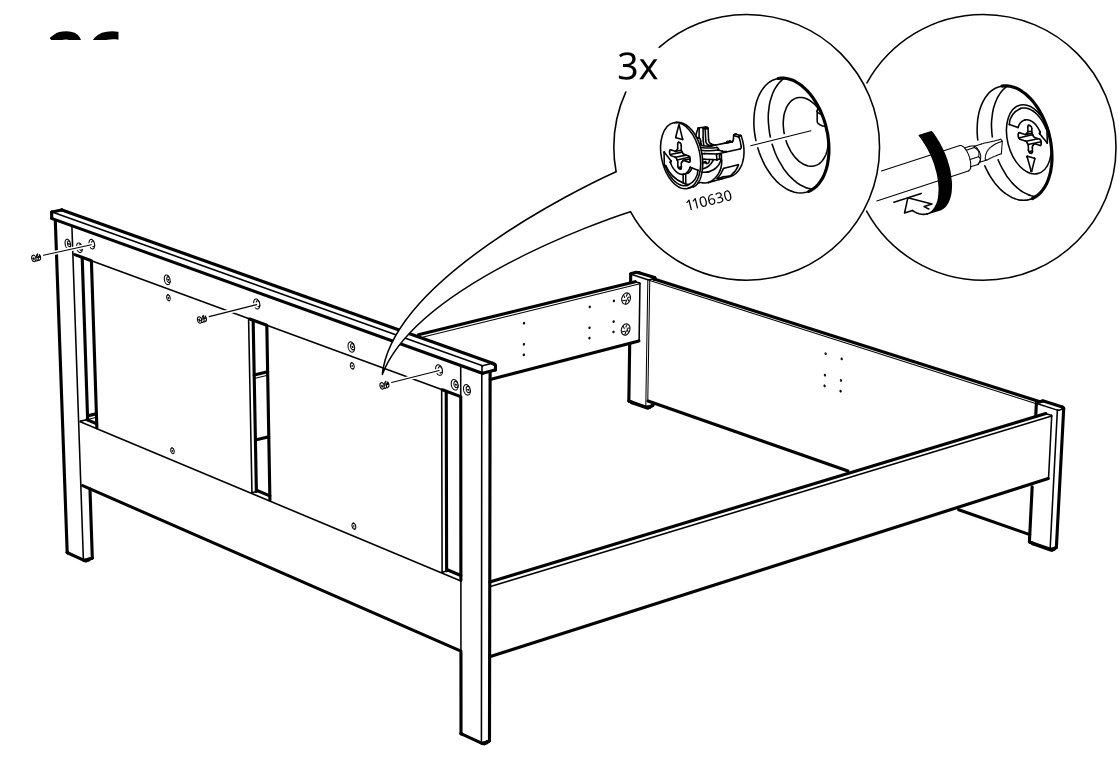
    Diagram for step 26: Three cam locks (110630) are inserted into the headboard side and then tightened with a screwdriver, as shown in the zoom callouts.
  31. Step 27

    The installer inserts and tightens nine cam locks into the marked holes on the headboard-side panels and rail connection points, as shown in the zoom callout.
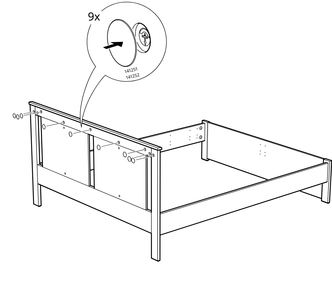
    Diagram for step 27: The installer inserts and tightens nine cam locks into the marked holes on the headboard-side panels and rail connection points, as shown in the zoom callout.
  32. Before you begin

    Info panel shows the correct way to angle and place the slats/rails into the bed frame and warns against dropping them straight down.
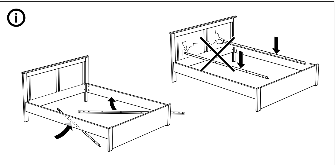
    Illustration for assembly note: Info panel shows the correct way to angle and place the slats/rails into the bed frame and warns against dropping them straight down.
  33. Step 28

    The bed frame slats and rails are secured by driving screws into the marked holes, with the top comparison panels indicating the correct side-rail positioning and alignment.
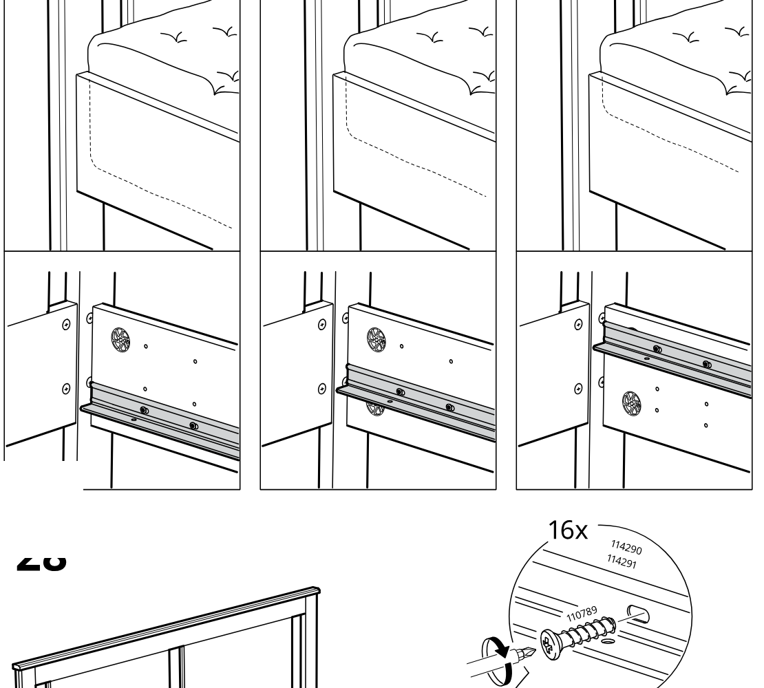
    Diagram for step 28: The bed frame slats and rails are secured by driving screws into the marked holes, with the top comparison panels indicating the correct side-rail positioning and alignment.
  34. Step 29

    Attach two 139301 brackets to the bed frame side panels using 105307 screws, with placement guided by the top comparison illustrations.
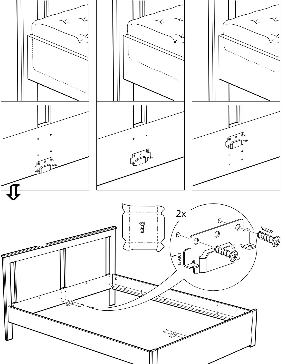
    Diagram for step 29: Attach two 139301 brackets to the bed frame side panels using 105307 screws, with placement guided by the top comparison illustrations.
  35. Step 30

    Slide plastic clip part 124402 onto the long rail and push it left into position, as shown in the zoom insets and main view.
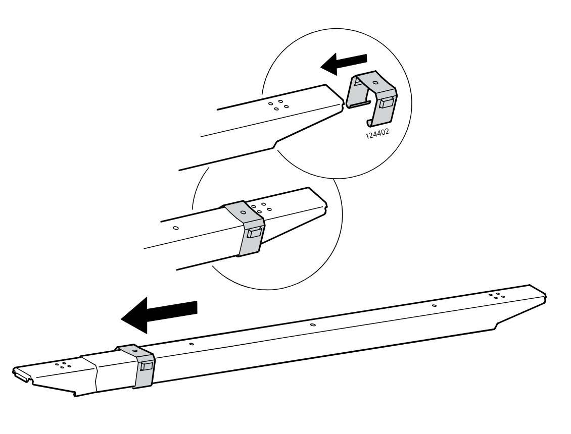
    Diagram for step 30: Slide plastic clip part 124402 onto the long rail and push it left into position, as shown in the zoom insets and main view.
  36. Step 31

    The center support rail is aligned and lowered into the rear bracket inside the bed frame.
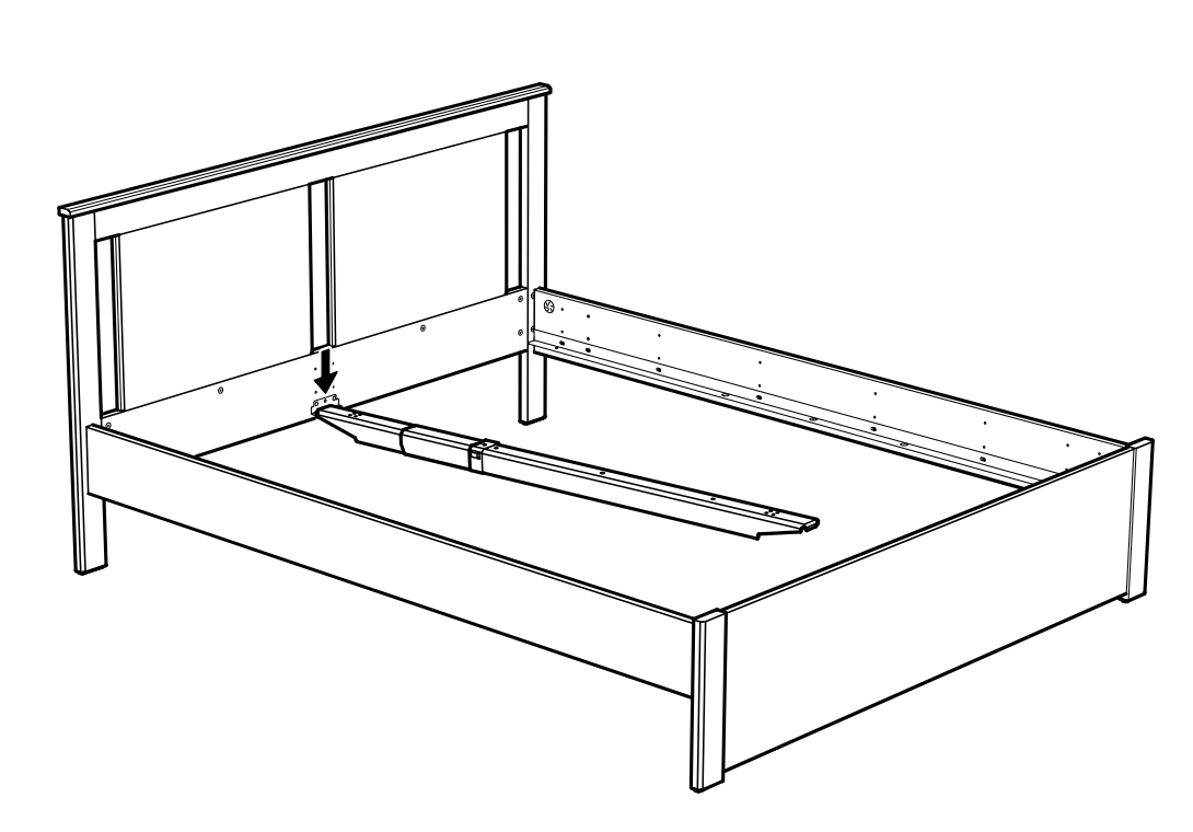
    Diagram for step 31: The center support rail is aligned and lowered into the rear bracket inside the bed frame.
  37. Step 32

    The center support rail is rotated down at the front with both hands until it engages the front connection point.
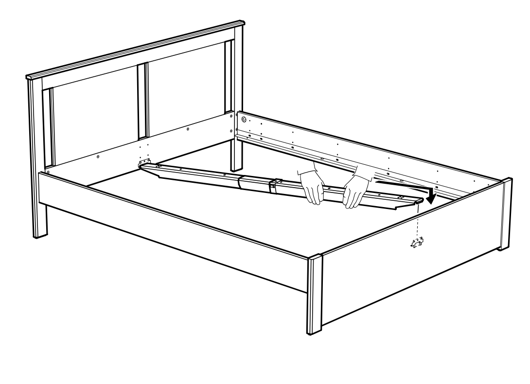
    Diagram for step 32: The center support rail is rotated down at the front with both hands until it engages the front connection point.
  38. Step 33

    The long rail is extended by sliding its telescoping section outward in opposite directions.
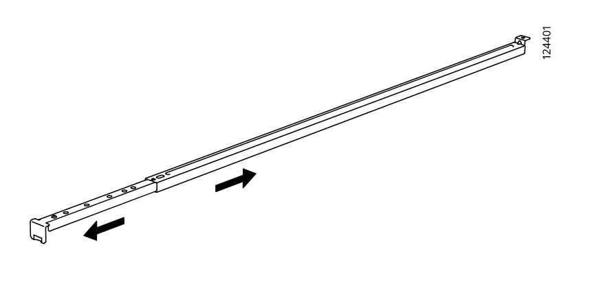
    Diagram for step 33: The long rail is extended by sliding its telescoping section outward in opposite directions.
  39. Step 34

    The extended center rail is positioned and hooked onto the bed frame brackets, then slid and lowered into place as shown in the zoom callouts.
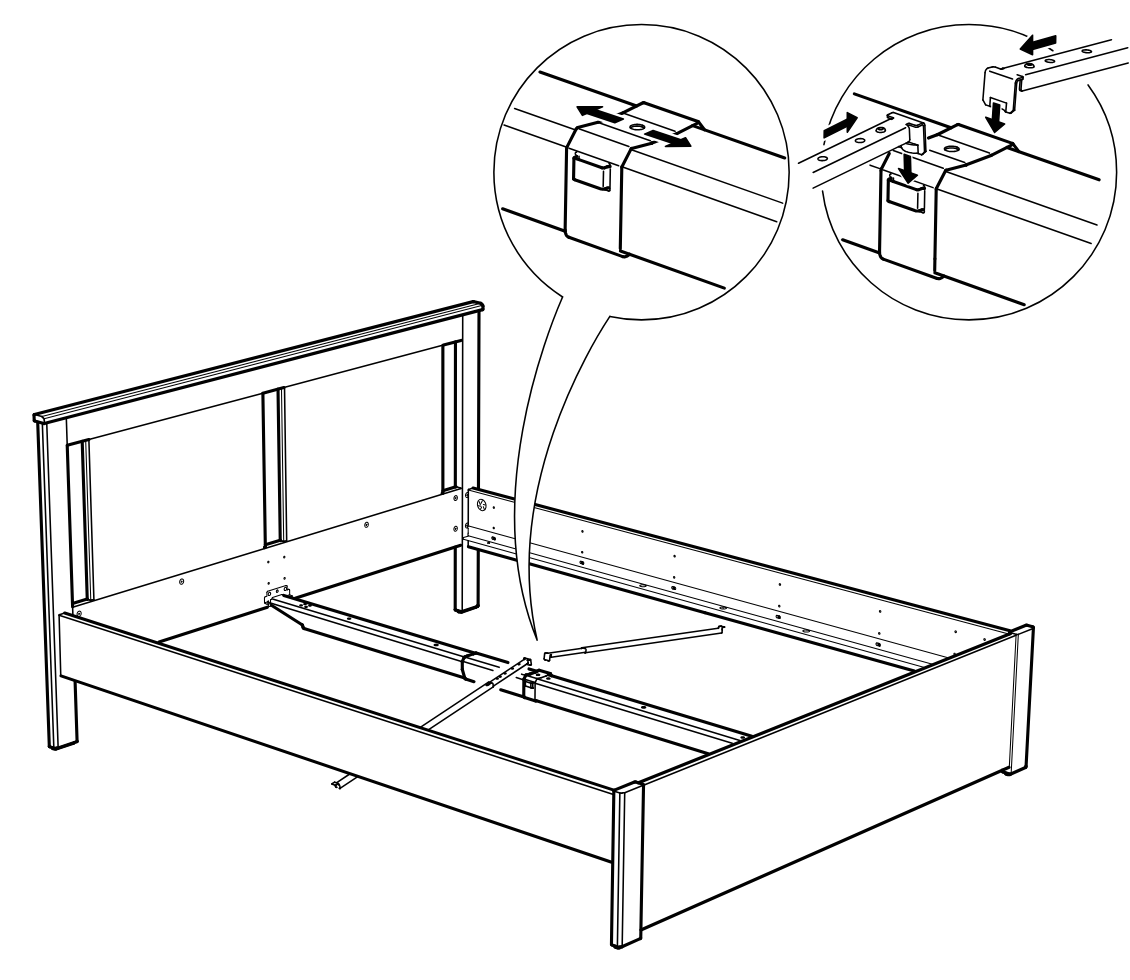
    Diagram for step 34: The extended center rail is positioned and hooked onto the bed frame brackets, then slid and lowered into place as shown in the zoom callouts.
  40. Step 35

    Tighten two 117327 screws in the side rail area while keeping the center support rail straight and level; the crossed diagram indicates the support must not bow upward.
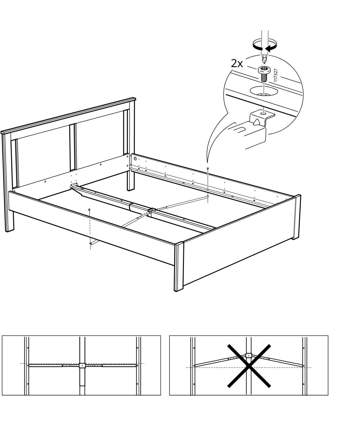
    Diagram for step 35: Tighten two 117327 screws in the side rail area while keeping the center support rail straight and level; the crossed diagram indicates the support must not bow upward.
  41. Step 36

    The side rail and center support are aligned and secured with two 117327 screws as shown in the zoom callout.
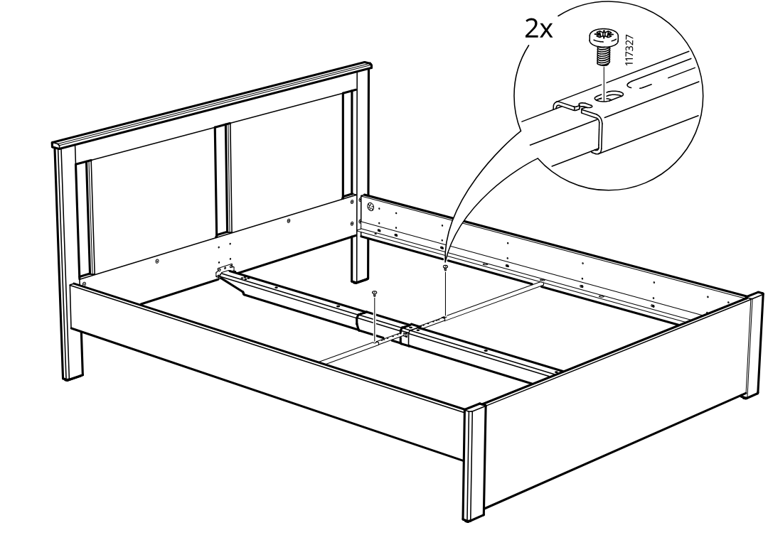
    Diagram for step 36: The side rail and center support are aligned and secured with two 117327 screws as shown in the zoom callout.
  42. Step 37

    The support bracket 117228 is positioned under the rail and fastened with 117327 screws, with the two zoom callouts showing the screw placements and bracket orientation.
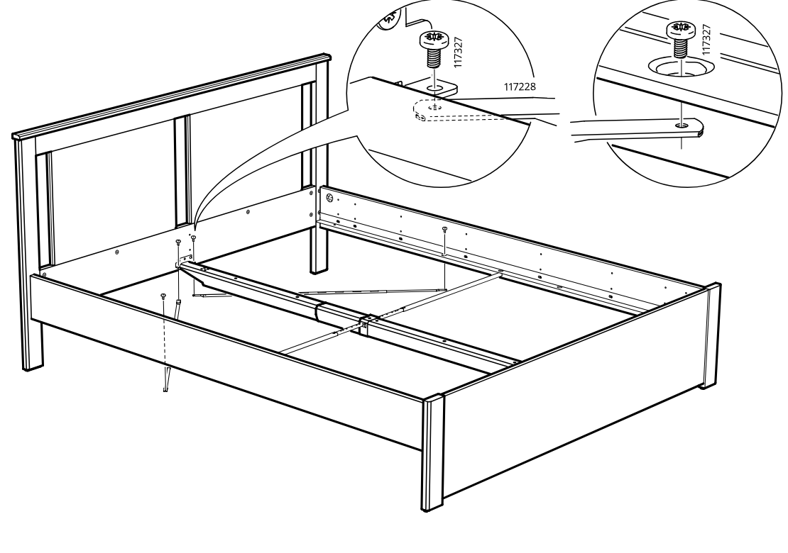
    Diagram for step 37: The support bracket 117228 is positioned under the rail and fastened with 117327 screws, with the two zoom callouts showing the screw placements and bracket orientation.
  43. Step 38

    The frame is secured with two screws into the side rail, then the base support orientation is checked so only the straight, square setup is accepted while skewed setups are rejected.
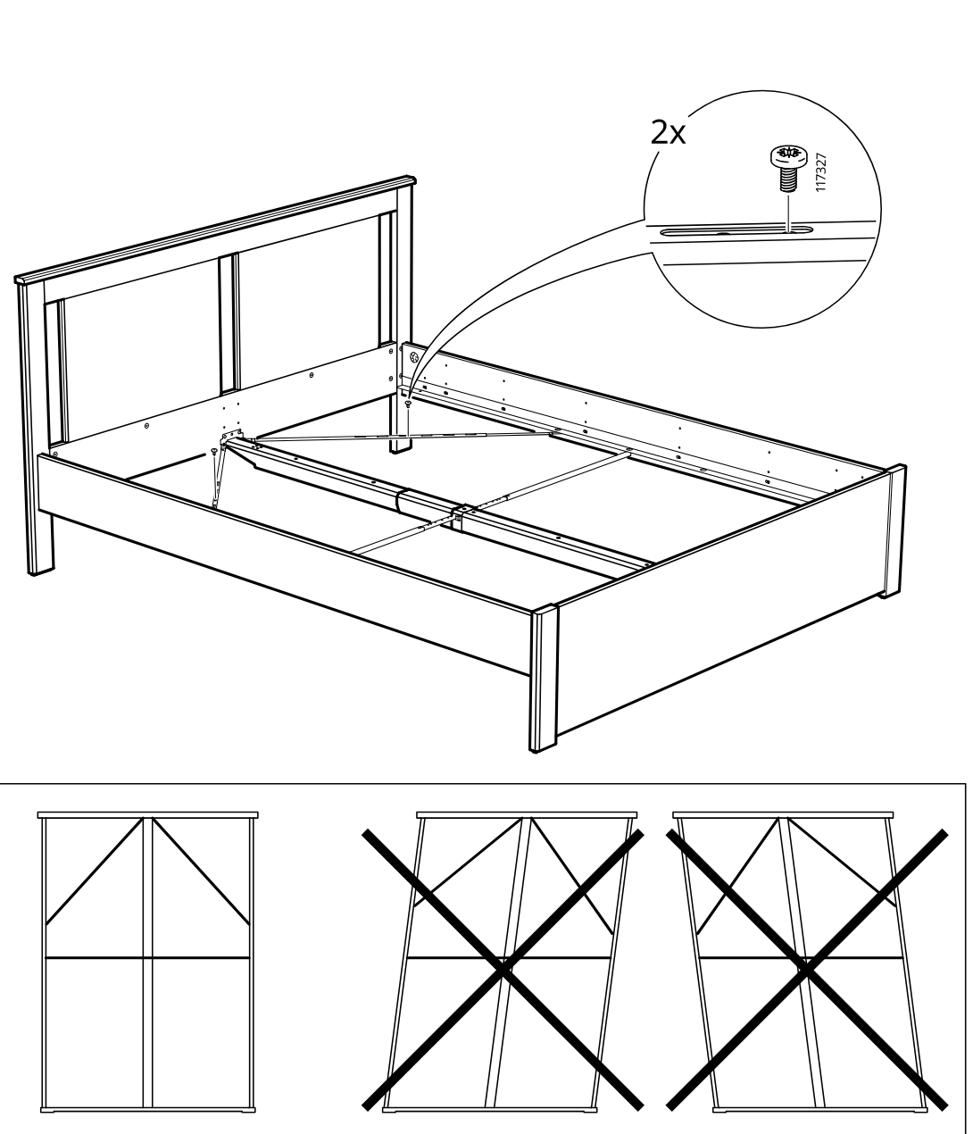
    Diagram for step 38: The frame is secured with two screws into the side rail, then the base support orientation is checked so only the straight, square setup is accepted while skewed setups are rejected.
  44. Before you begin

    Information page shows slatted base configuration options and installation guidance: left column shows lifting bed base preparation and a do-not-use hardware comparison (105163 vs 191315), while right column shows fixed bed frame slat placement with 8x clips/screws and a page-turn icon directing to page 31.
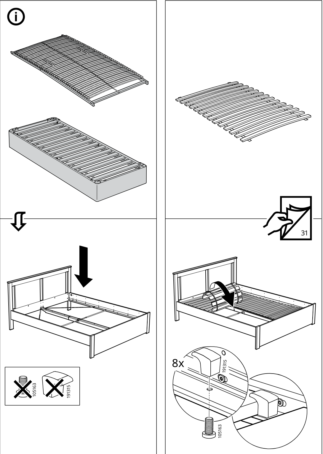
    Illustration for assembly note: Information page shows slatted base configuration options and installation guidance: left column shows lifting bed base preparation and a do-not-use hardware comparison (105163 vs 191315), while right column shows fixed bed frame slat placement with 8x clips/screws and a page-turn icon directing to page 31.
  45. Before you begin

    Information panel shows rolling out and positioning the slatted bed base, then fastening clips and screw 105163 (8x) with close-up callouts.
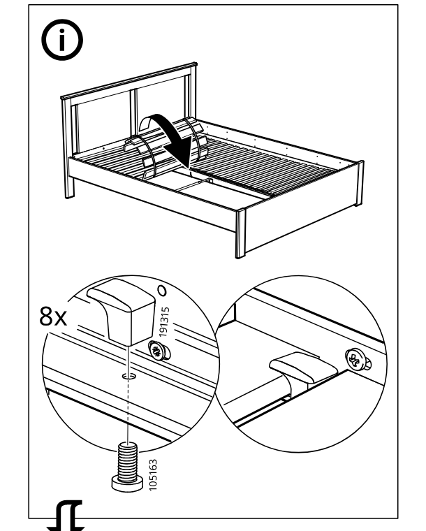
    Illustration for assembly note: Information panel shows rolling out and positioning the slatted bed base, then fastening clips and screw 105163 (8x) with close-up callouts.
  46. Step 39

    The bed frame is assembled by securing multiple fasteners around the side rails, headboard, and center support structure.
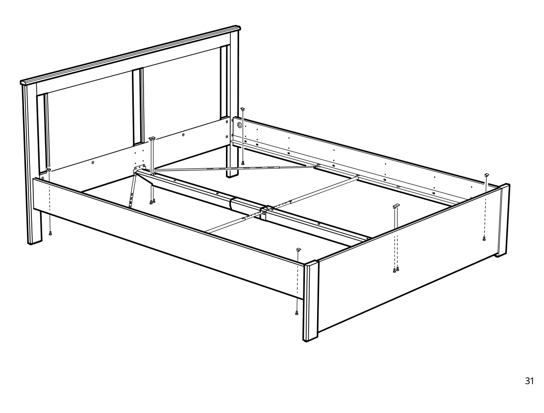
    Diagram for step 39: The bed frame is assembled by securing multiple fasteners around the side rails, headboard, and center support structure.

Video guide