TARVA Bed frame
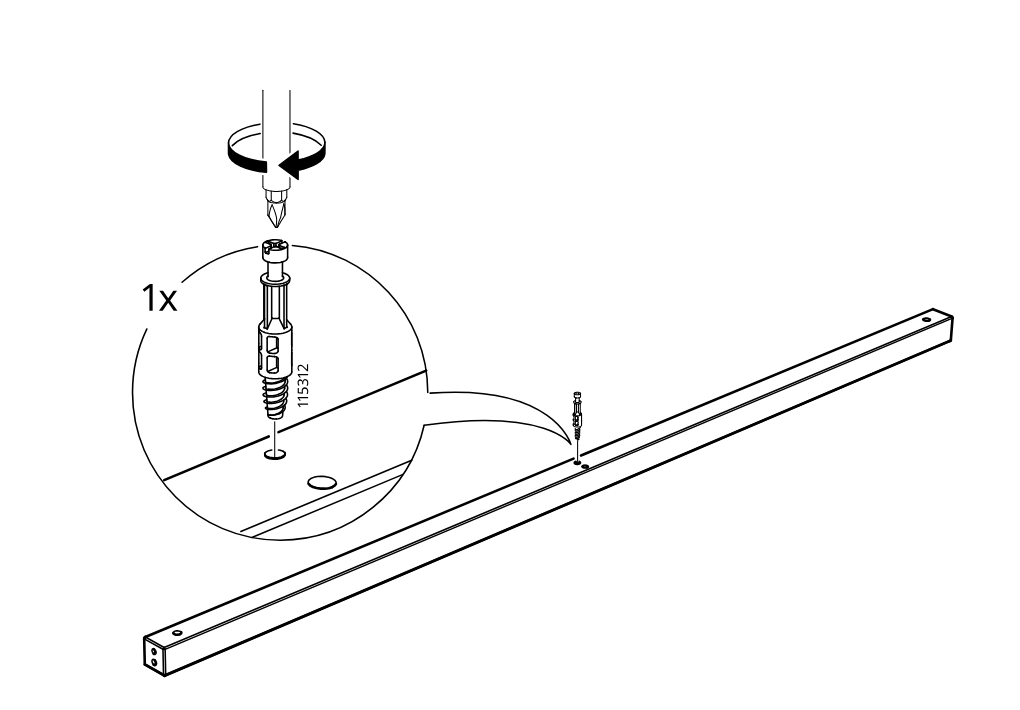
Step 1
A cam screw (115312) is inserted into the rail and tightened with a screwdriver, shown with a zoomed detail and 1x quantity.
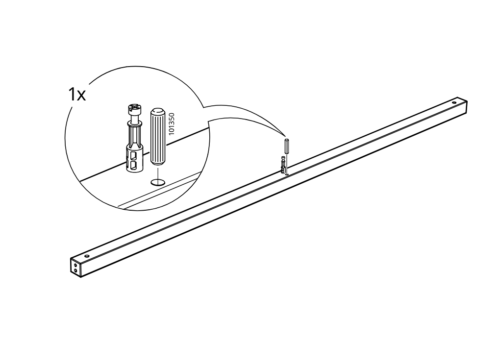
Step 2
A plastic sleeve (101350) is placed over the installed cam screw on the rail, shown in a zoomed detail with 1x quantity.
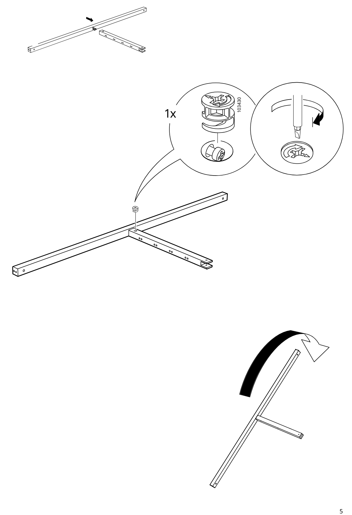
Step 3
The long rail is joined perpendicularly to the shorter perforated rail, one cam lock (103430) is inserted and tightened with a screwdriver, and the assembled frame is then rotated as indicated.
Step 4
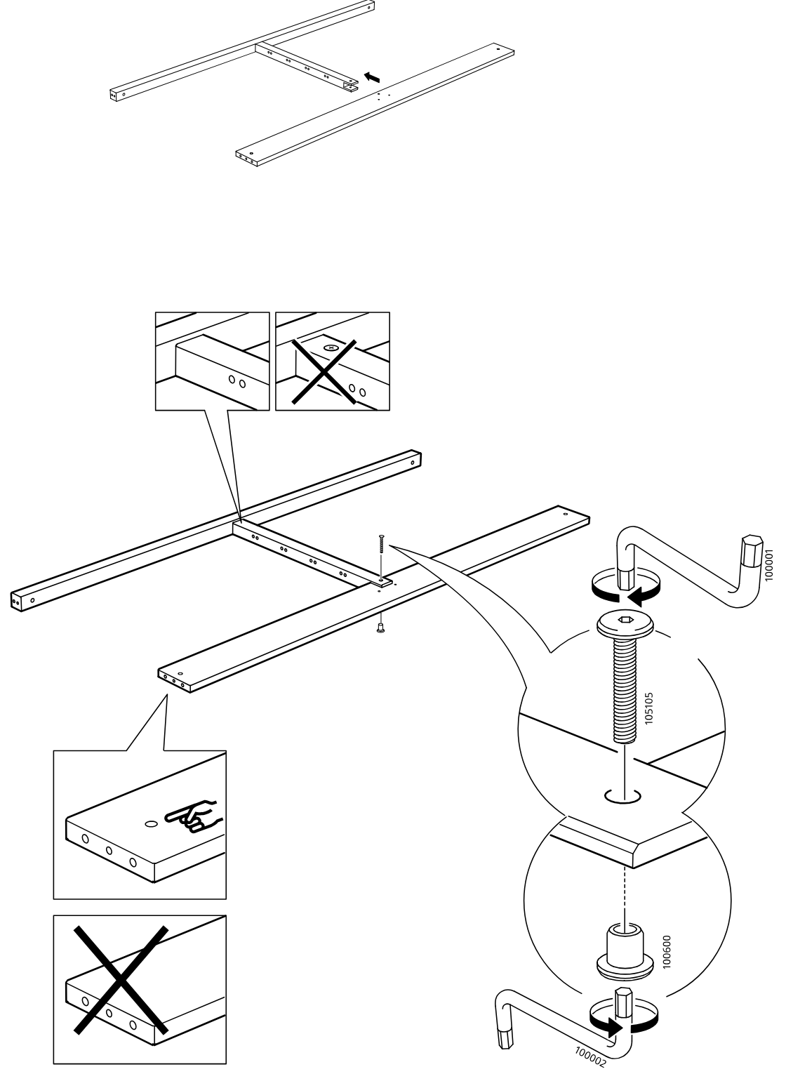
The long rail assembly is aligned onto the board and fastened with screw 105105 into insert 100600 using hex key 100001/100002, while the callouts show the correct board orientation and to avoid placing the fastener in the wrong hole.
Step 5
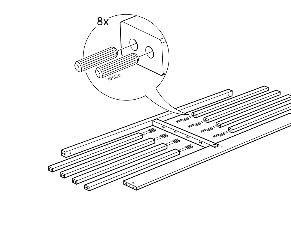
The builder inserts eight wooden dowels (101350) into the predrilled ends of the long frame rails as shown in the zoom detail.
Step 6
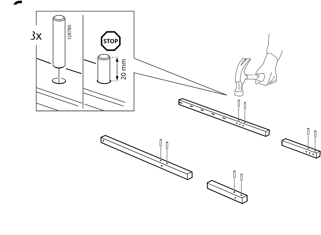
The builder taps eight 128780 pins into the rail holes and stops when each pin remains about 20 mm above the surface, using a hammer as indicated.
Step 7
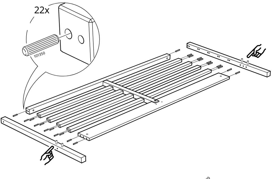
The side rails and slats are aligned and dowels are inserted into the rail holes, with a zoom detail showing part 101350 used 22 times.
Step 8
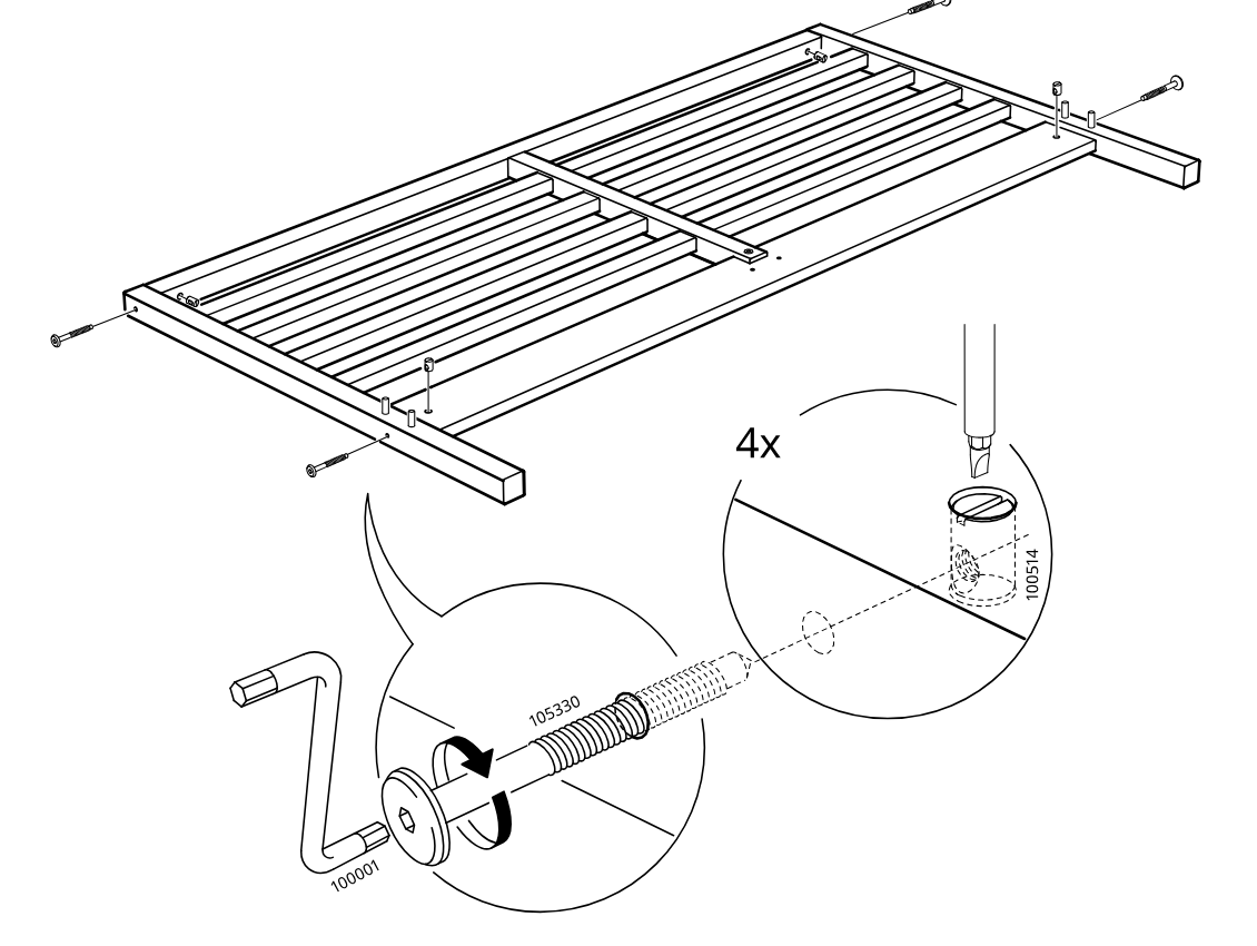
Long connector bolts are tightened with the hex key while cam fittings are set and oriented, as shown in the two zoom callouts.
Step 9
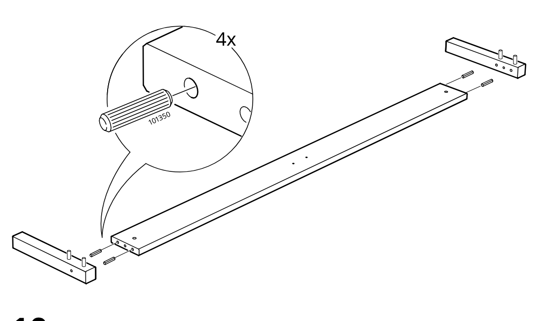
The side rail is joined between two end blocks using four dowels, with a zoom callout showing dowel 101350 insertion.
Step 10
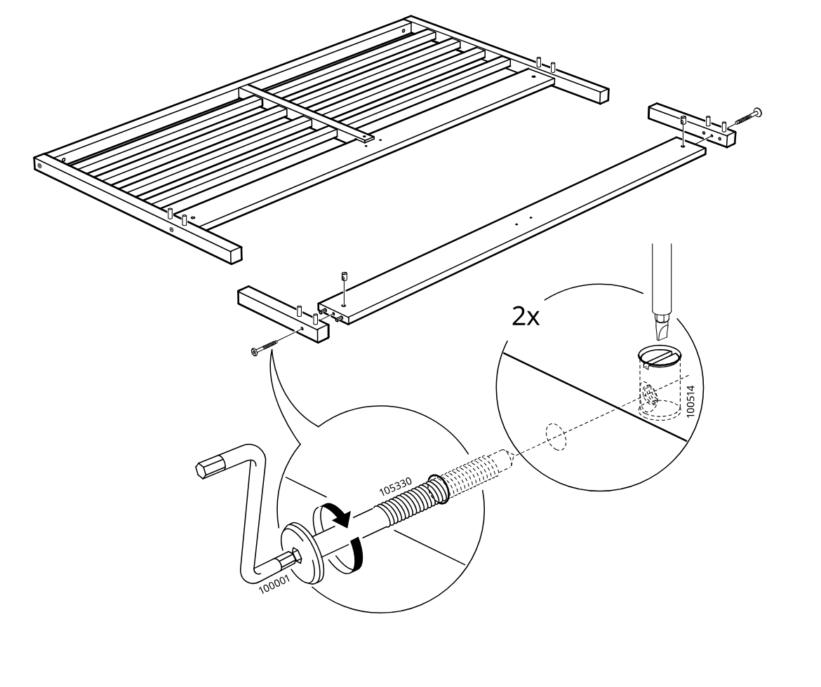
The long side member is attached to the slatted frame and end blocks, then two cam fittings 100514 are inserted and tightened with connector 105330 using hex key 100001.
Step 11
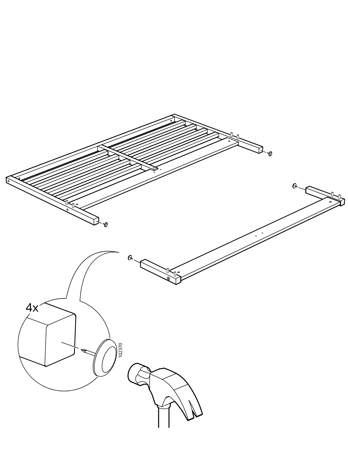
The frame assembly is shown with side rail parts separated, and four felt pads (102370) are hammered onto the indicated rail ends.
Step 12
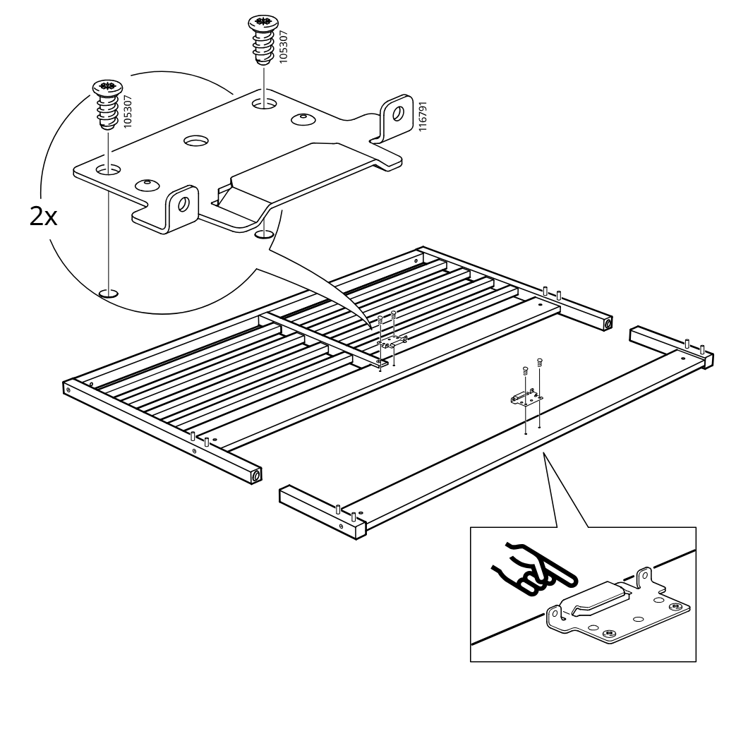
Two screws fasten the metal bracket to the bed frame rail, with the bracket orientation confirmed by the finger-pointing inset.
Step 13
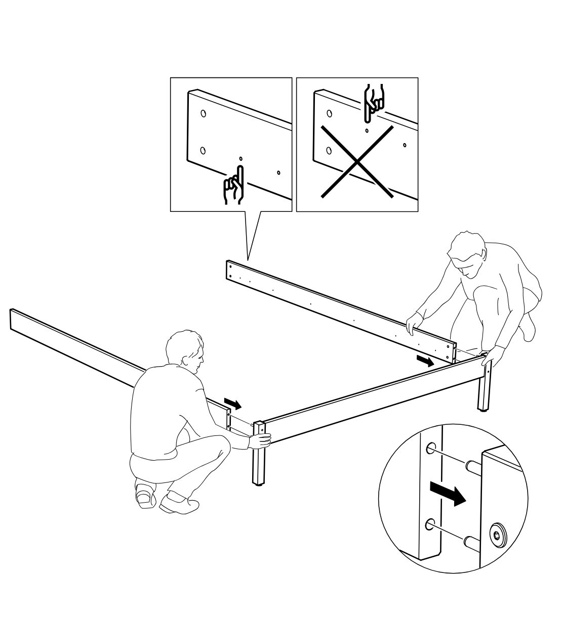
Two people align and slide the long side panels onto the corner posts/frame ends, following the hole orientation shown in the do/don't inset and the zoom detail.
Step 14
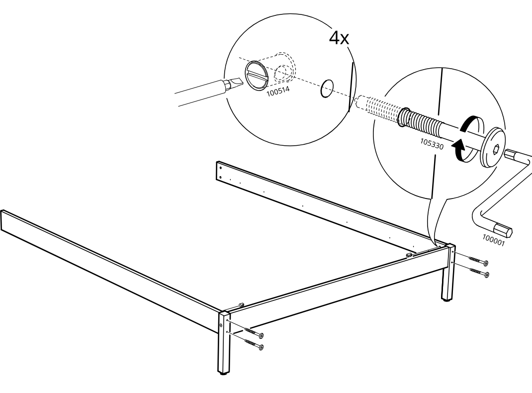
The side rails are secured to the frame corners with cam fasteners, tightening the connector bolts using the included Allen key as shown in the zoom callouts.
Step 15
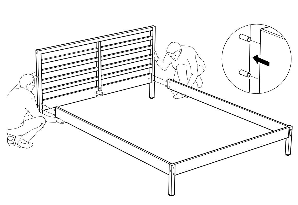
Two people position and slide the slatted headboard assembly onto the exposed dowels/posts at the frame end to join the bed structure.
Step 16
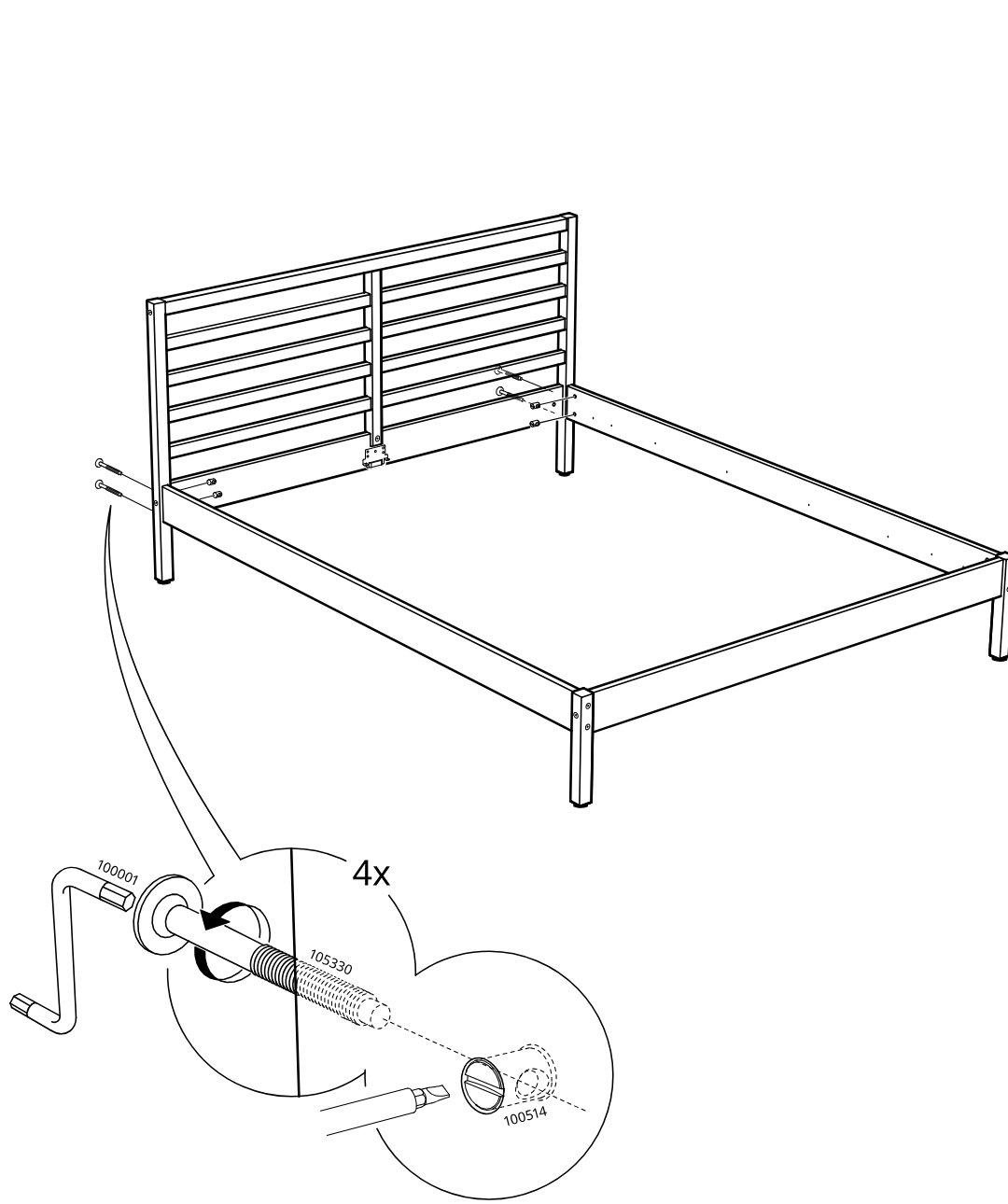
Attach the side rails to the headboard with four long bolts, tightening with the Allen key while using a screwdriver to hold the slotted barrel nut in alignment.
Step 17
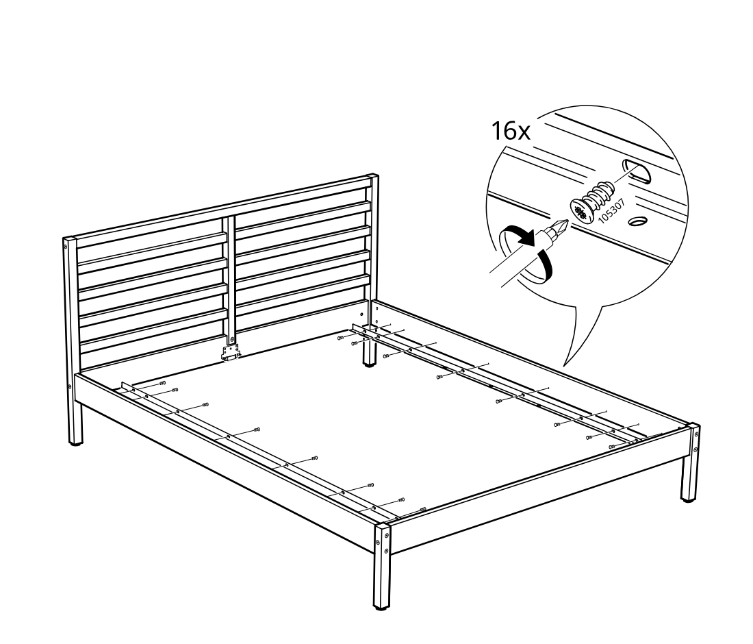
The assembler fastens the bed slats to the frame using 16 screws (part 105307), with the inset showing screwdriver direction and screw placement.
Step 18
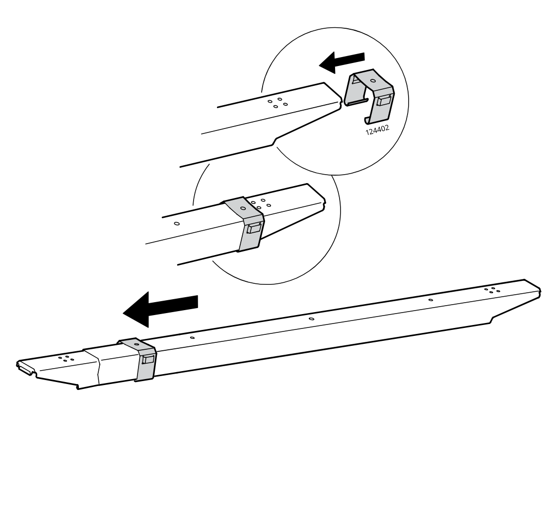
Slide clip part 124402 onto the end of the long rail and push it left until it locks in place, as shown in the zoom callouts.
Step 19
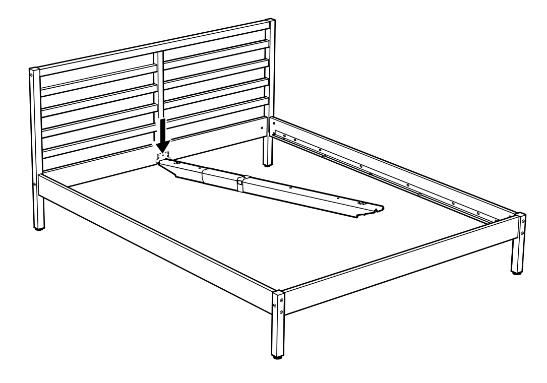
The slatted headboard section is lowered into position at the center bracket while the folded center support beam rests across the bed frame.
Step 20
The center support beam is unfolded and guided forward by hand to seat its end into the front frame bracket.
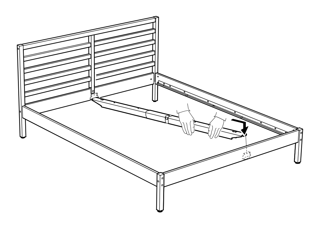
Step 21
Two center support rails (124401) are positioned into the bed frame, and one screw (117327) is tightened from above to secure the rail connection as shown in the zoom inset.
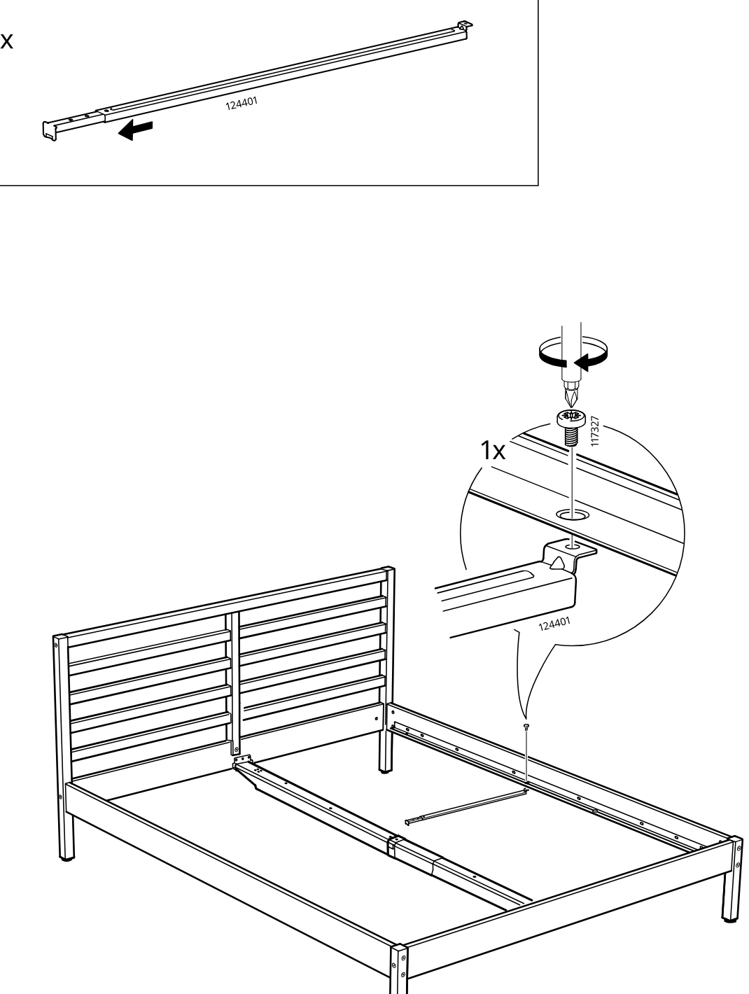
Step 22
The center rail is slid and locked into position on the bed frame, with zoom callouts showing the correct horizontal orientation and insertion of part 124401.
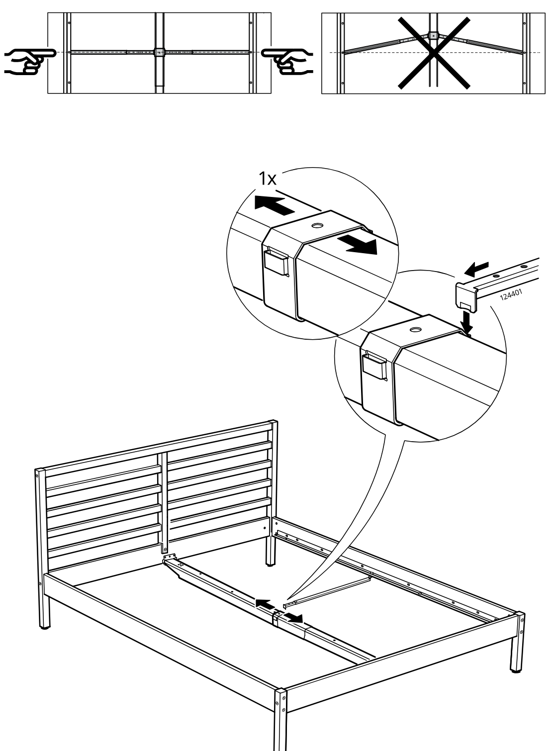
Step 23
The side rail connector is hooked into the frame and secured with one screw at the indicated joint.
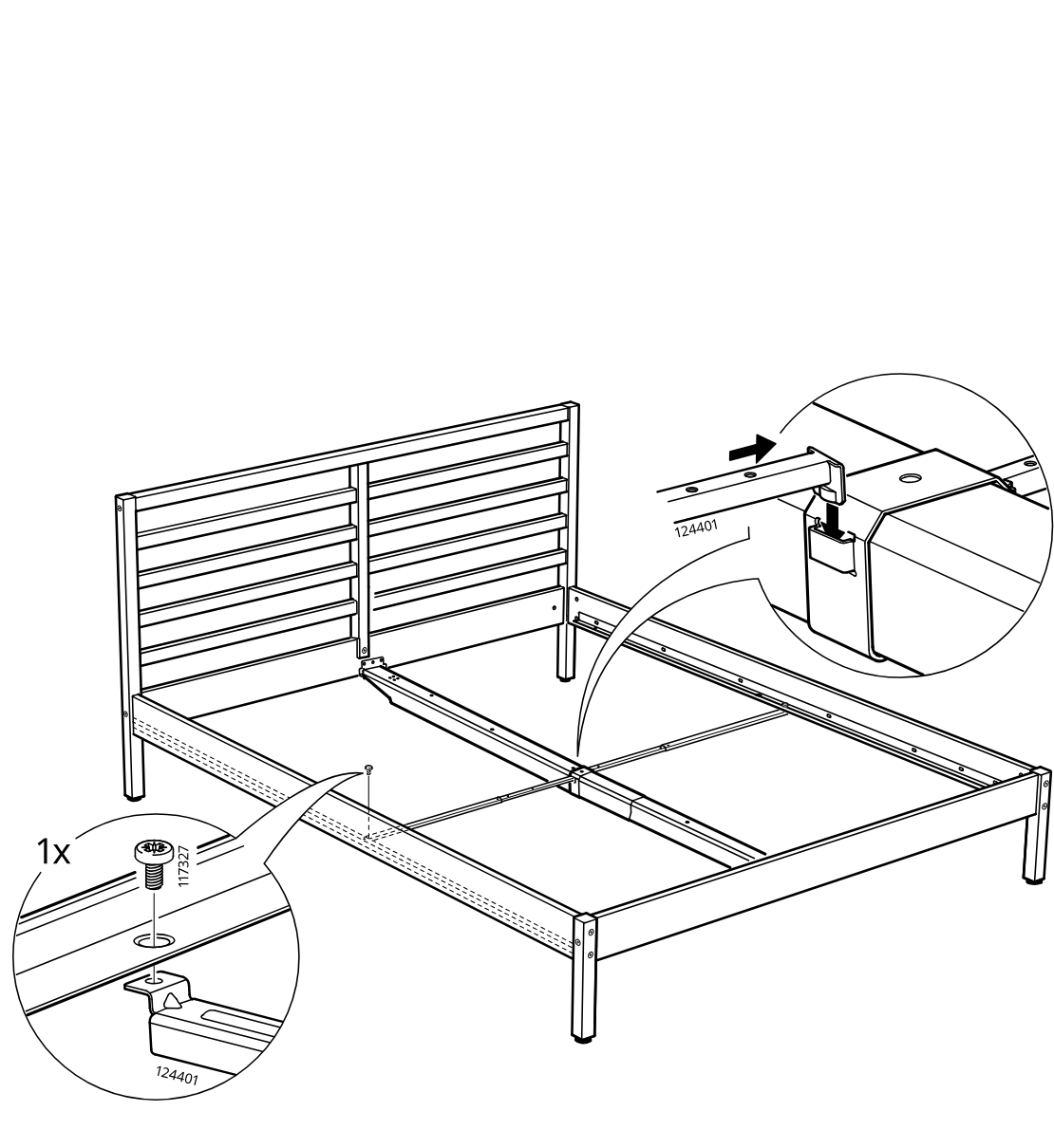
Step 24
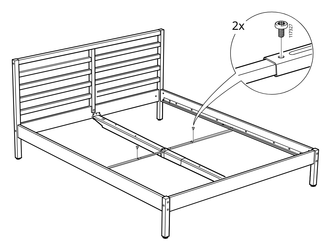
The bed frame is shown assembled with the center support in place, and two screws (117327) are inserted to fasten the overlapping rail connection as highlighted in the zoom callout.