How to assemble IKEA TROFAST storage combination with boxes

TROFAST storage combination with boxes, white/white, 39x173/8x22"

This guide covers the white/white IKEA TROFAST storage combination with boxes, 595.744.59. The assembly section below provides diagrams and video for the TROFAST frame.

View on IKEA
TROFAST storage combination with boxes

Interactive assembly guide

Step-by-Step Instructions

1 different parts, 1 boxes total — click on a package to see step-by-step assembly instructions

TROFAST Frame

801.538.00

x1

19 "

Width

2 ¾ "

Height

48 ½ "

Length

50 lb 11 oz

Weight

Start Assembly

Written guide

Step-by-step instructions with diagrams

Follow the numbered assembly steps below, or open the interactive guide above to track progress and zoom into each diagram. This guide includes 12 illustrated steps.

TROFAST Frame

  1. Before you begin

    Preparation and safety guidance panels show using a screwdriver correctly, avoiding assembly on a hard surface, assembling on a soft surface, and seeking help or contacting IKEA support if unsure.
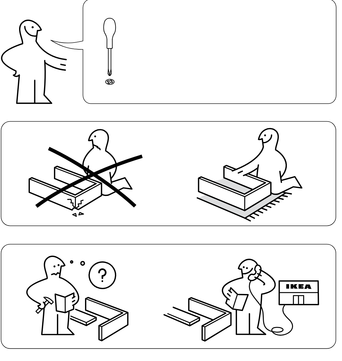
    Illustration for assembly note: Preparation and safety guidance panels show using a screwdriver correctly, avoiding assembly on a hard surface, assembling on a soft surface, and seeking help or contacting IKEA support if unsure.
  2. Step 1

    The installer inserts four 101354 wooden dowels into the indicated side panel edge holes and prepares two rails for attachment, with a zoomed inset showing correct dowel type versus crossed-out 101350.
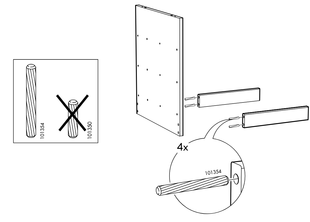
    Diagram for step 1: The installer inserts four 101354 wooden dowels into the indicated side panel edge holes and prepares two rails for attachment, with a zoomed inset showing correct dowel type versus crossed-out 101350.
  3. Step 2

    The installer joins two side panels with the rails and inserts four 101354 wooden dowels into the exposed rail-side holes, with a zoomed inset and crossed-out 101350 reminder.
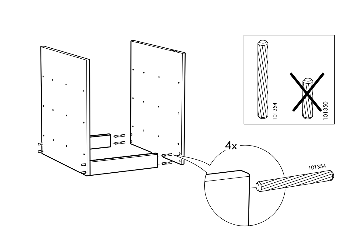
    Diagram for step 2: The installer joins two side panels with the rails and inserts four 101354 wooden dowels into the exposed rail-side holes, with a zoomed inset and crossed-out 101350 reminder.
  4. Step 3

    The two side panels and center supports are aligned above the bottom board, and four dowels (part 101350) are inserted as indicated by the zoom callout.
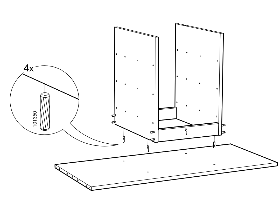
    Diagram for step 3: The two side panels and center supports are aligned above the bottom board, and four dowels (part 101350) are inserted as indicated by the zoom callout.
  5. Step 4

    Long side rails are slid inward from both left and right sides into the lower frame, following the horizontal arrow directions.
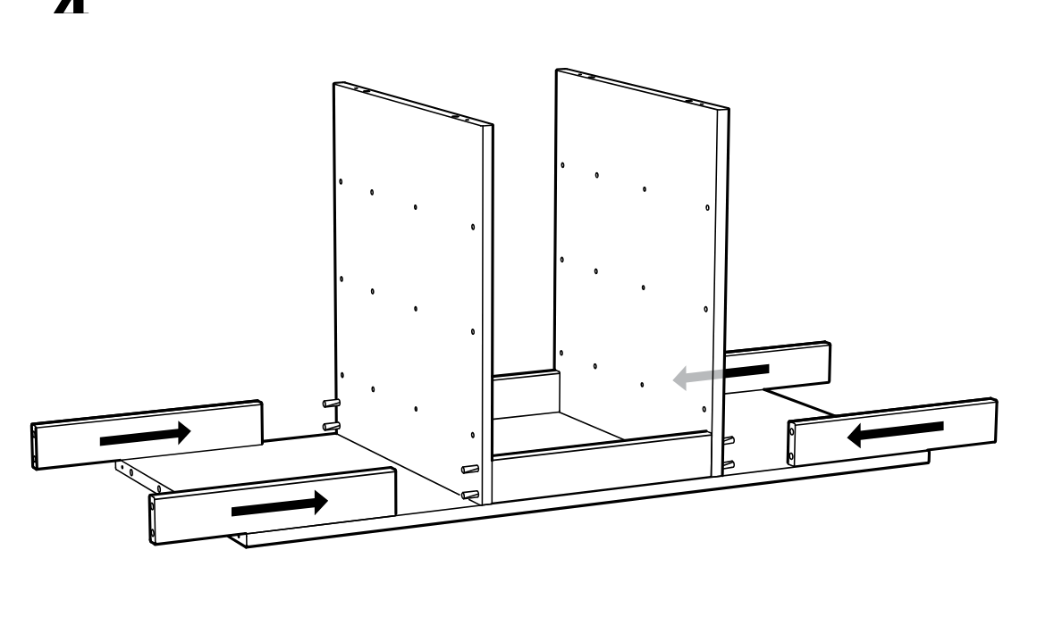
    Diagram for step 4: Long side rails are slid inward from both left and right sides into the lower frame, following the horizontal arrow directions.
  6. Step 5

    The top panel is aligned above the two vertical dividers, and four dowels (101350) are inserted into the top edges of the dividers.
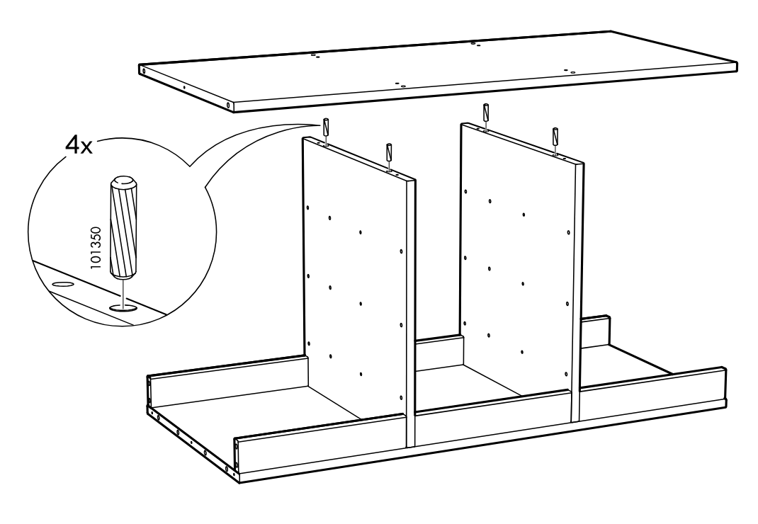
    Diagram for step 5: The top panel is aligned above the two vertical dividers, and four dowels (101350) are inserted into the top edges of the dividers.
  7. Step 6

    The top panel is set in place and four screws (100229) are tightened from above using the hex key (100006).
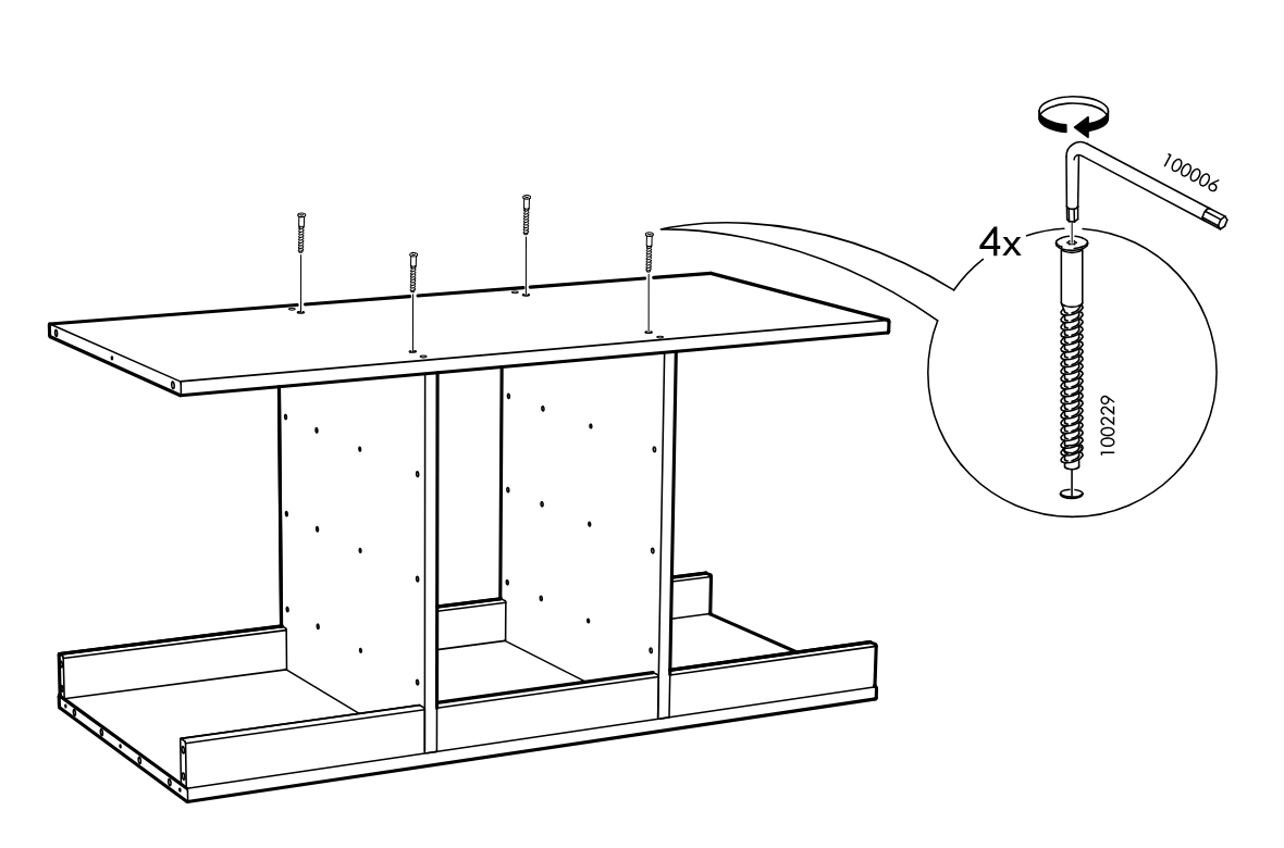
    Diagram for step 6: The top panel is set in place and four screws (100229) are tightened from above using the hex key (100006).
  8. Step 7

    Two long rails are lowered onto the dowels on the top panel, while a zoom callout shows inserting four dowels (101350) into the panel holes.
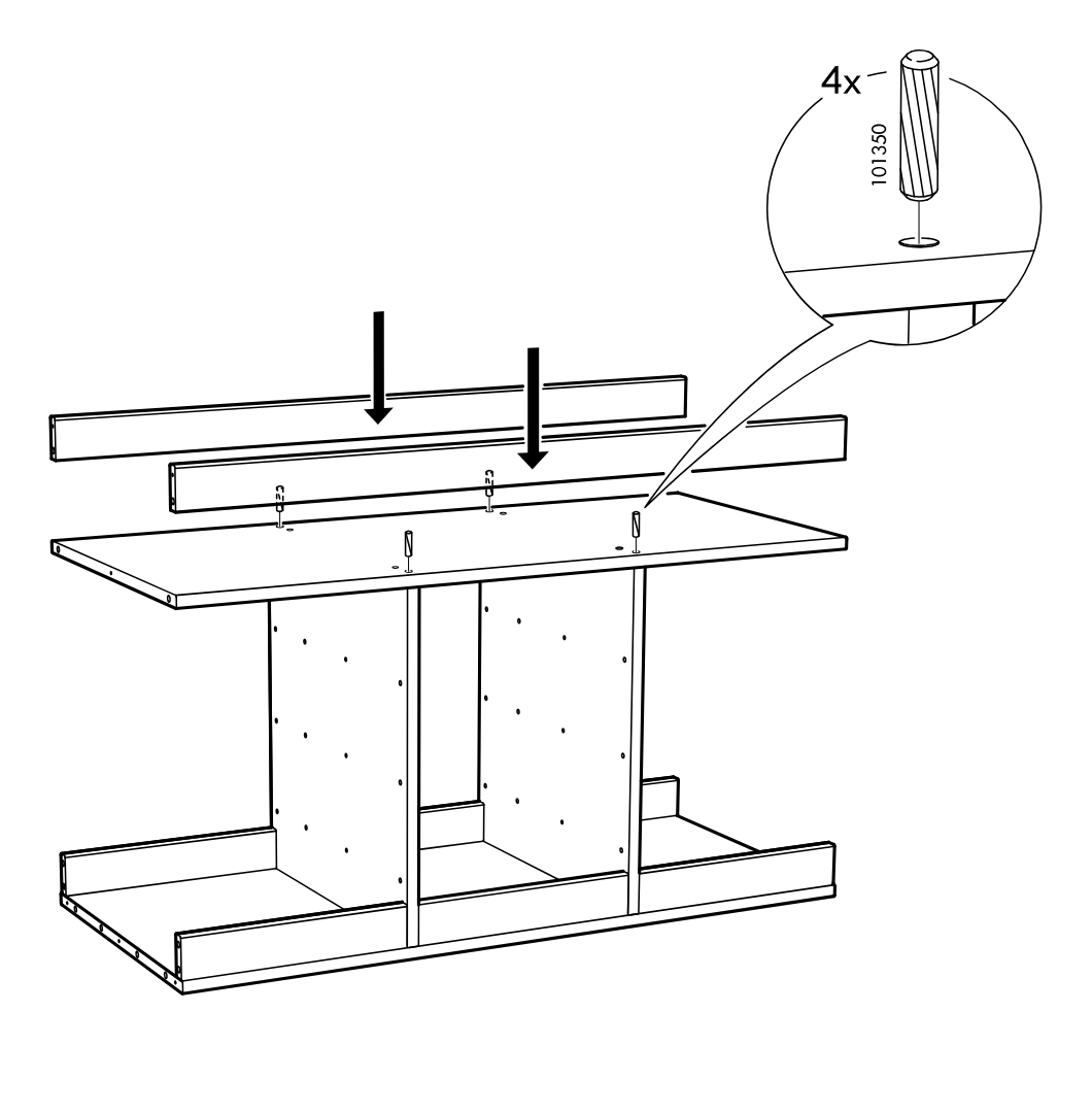
    Diagram for step 7: Two long rails are lowered onto the dowels on the top panel, while a zoom callout shows inserting four dowels (101350) into the panel holes.
  9. Step 8

    Insert twelve wooden dowels (101350) into the side and rail connection holes, then align the left side panel with the frame assembly.
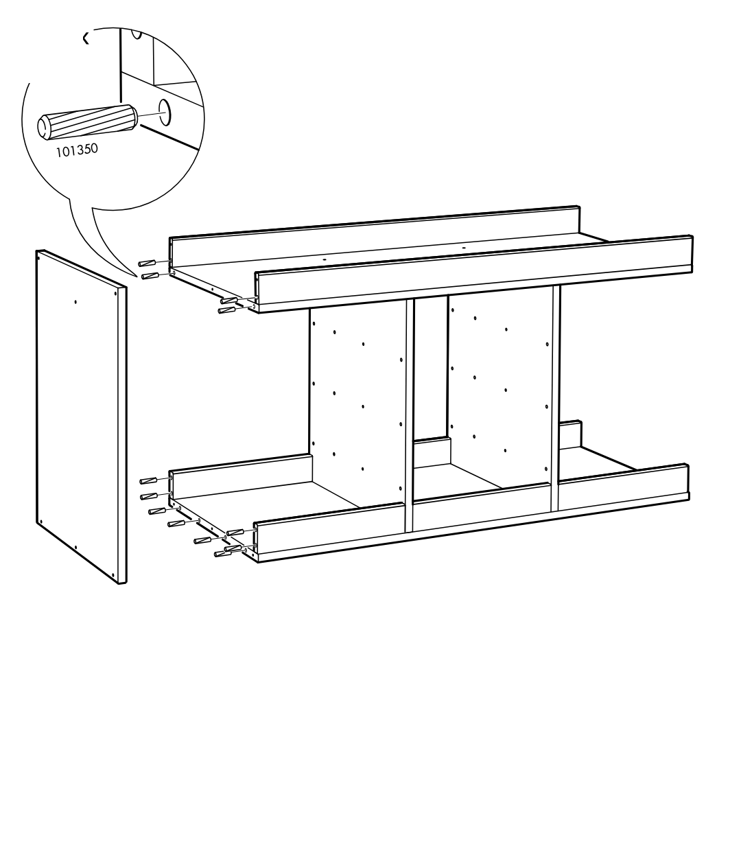
    Diagram for step 8: Insert twelve wooden dowels (101350) into the side and rail connection holes, then align the left side panel with the frame assembly.
  10. Step 9

    Using the 100006 hex key, six 100229 cam screws are driven into the left side and front edge holes of the cabinet frame, with a zoom callout showing the correct screw depth and orientation.
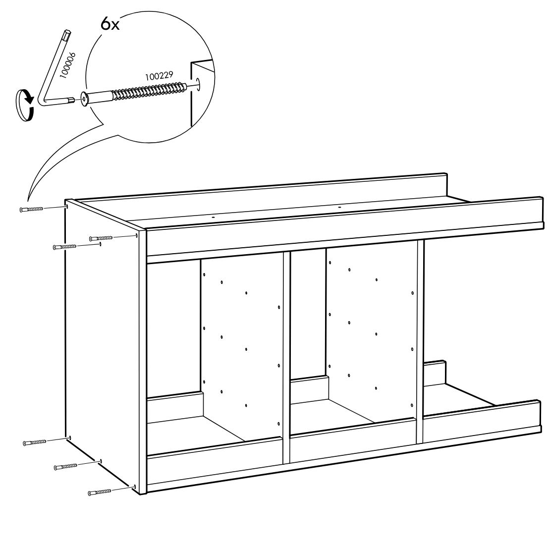
    Diagram for step 9: Using the 100006 hex key, six 100229 cam screws are driven into the left side and front edge holes of the cabinet frame, with a zoom callout showing the correct screw depth and orientation.
  11. Step 10

    The side panel is aligned to the cabinet frame and attached using multiple wooden dowels, with a zoom callout indicating 12 dowels of part 101350.
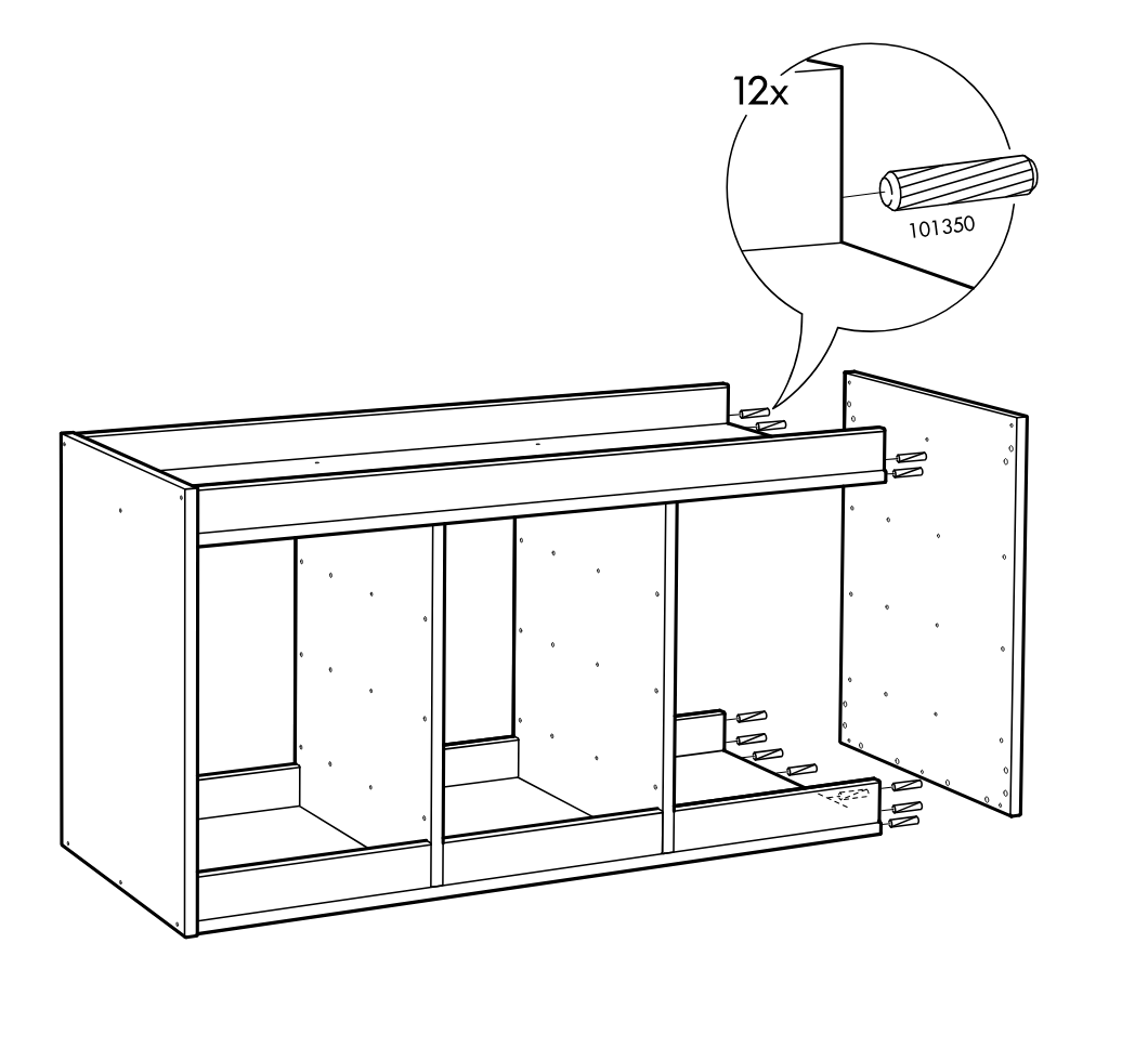
    Diagram for step 10: The side panel is aligned to the cabinet frame and attached using multiple wooden dowels, with a zoom callout indicating 12 dowels of part 101350.
  12. Step 11

    Tighten six 100229 screws into the cabinet frame using the 100006 hex key, as shown in the zoomed detail.
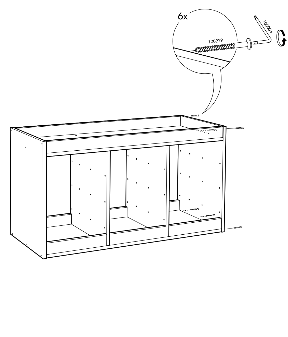
    Diagram for step 11: Tighten six 100229 screws into the cabinet frame using the 100006 hex key, as shown in the zoomed detail.
  13. Step 12

    The cabinet frame is turned and the drawer rails are fastened across the compartments using 18 screws with a screwdriver, as shown in the zoomed detail.
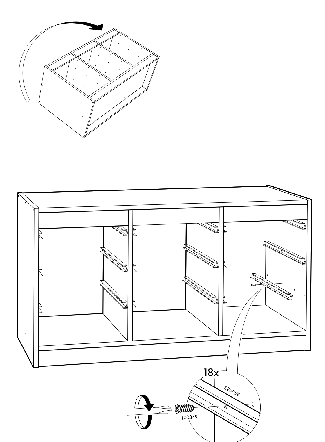
    Diagram for step 12: The cabinet frame is turned and the drawer rails are fastened across the compartments using 18 screws with a screwdriver, as shown in the zoomed detail.

Video guide